logo资料库

liberty user guide.pdf

第1页 / 共1542页
第2页 / 共1542页
第3页 / 共1542页
第4页 / 共1542页
第5页 / 共1542页
第6页 / 共1542页
第7页 / 共1542页
第8页 / 共1542页
资料共1542页,剩余部分请下载后查看
Liberty_cover
Liberty User Guides and Reference Manual Suite Version 2012.06.pdf
Liberty User Guides and Reference Manual Suite Version 2012.06
Liberty (Version 2012.06)
TOC: Liberty User Guide, Vol. 1
TOC: Liberty User Guide, Vol. 2
TOC: Liberty Reference Manual
Liberty User Guide, Vol. 1 (Version 2012.06)
Index (Version )
Liberty User Guide, Vol. 2 (Version 2012.06)
Index (Version )
Liberty Reference Manual (Version 2012.06)
Index (Version )
TOC:
Liberty User Guides and Reference Manual Suite Version 2012.06 1 The Liberty User Guides and Reference Manual Suite includes the following documentation: Liberty Release Notes; Liberty User Guide, Volume 1; Liberty User Guide, Volume 2; and Liberty Reference Manual. Note: Although the version number for the Liberty User Guide, Volume 2 was updated to 2012.06 in order to be consistent with the rest of the Liberty documentation, its contents have not changed since the 2007.03 release. You can use Adobe Reader version 7 or later to view the Liberty User Guides and Reference Manual Suite. For best viewing, use Adobe Reader version X. You can download Adobe Reader version X for free from: http://www.adobe.com/products/acrobat/readstep2.html To navigate through the Liberty User Guides and Reference Manual Suite, you can use the View > Go To menu item and select the appropriate option.
Liberty (Version 2012.06) Liberty User Guide, Vol. 1 Liberty User Guide, Vol. 2 Liberty Reference Manual Liberty User Guides and Reference Manual Suite Version 2012.061
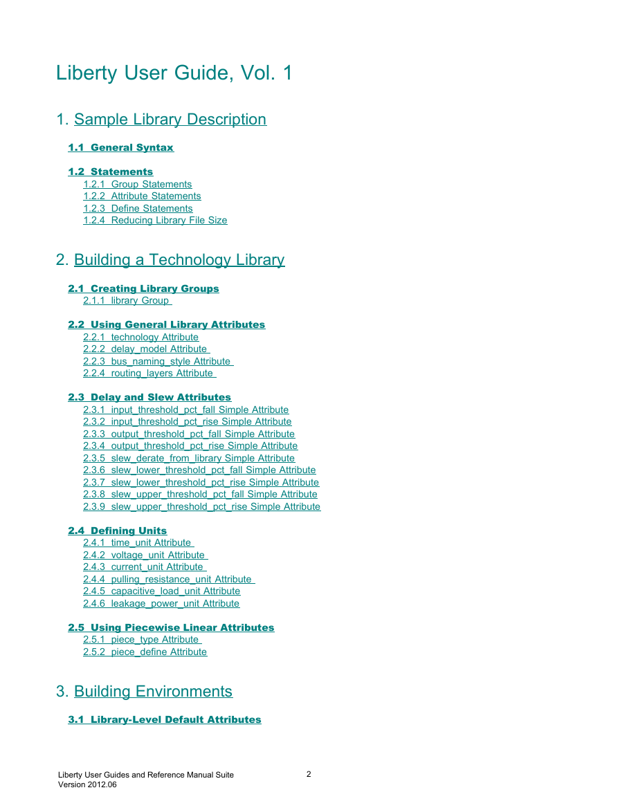
Liberty User Guide, Vol. 1 1. Sample Library Description 1.1 General Syntax 1.2 Statements 1.2.1 Group Statements 1.2.2 Attribute Statements 1.2.3 Define Statements 1.2.4 Reducing Library File Size 2. Building a Technology Library 2.1 Creating Library Groups 2.1.1 library Group 2.2 Using General Library Attributes 2.2.1 technology Attribute 2.2.2 delay_model Attribute 2.2.3 bus_naming_style Attribute 2.2.4 routing_layers Attribute 2.3 Delay and Slew Attributes 2.3.1 input_threshold_pct_fall Simple Attribute 2.3.2 input_threshold_pct_rise Simple Attribute 2.3.3 output_threshold_pct_fall Simple Attribute 2.3.4 output_threshold_pct_rise Simple Attribute 2.3.5 slew_derate_from_library Simple Attribute 2.3.6 slew_lower_threshold_pct_fall Simple Attribute 2.3.7 slew_lower_threshold_pct_rise Simple Attribute 2.3.8 slew_upper_threshold_pct_fall Simple Attribute 2.3.9 slew_upper_threshold_pct_rise Simple Attribute 2.4 Defining Units 2.4.1 time_unit Attribute 2.4.2 voltage_unit Attribute 2.4.3 current_unit Attribute 2.4.4 pulling_resistance_unit Attribute 2.4.5 capacitive_load_unit Attribute 2.4.6 leakage_power_unit Attribute 2.5 Using Piecewise Linear Attributes 2.5.1 piece_type Attribute 2.5.2 piece_define Attribute 3. Building Environments 3.1 Library-Level Default Attributes Liberty User Guides and Reference Manual Suite Version 2012.062
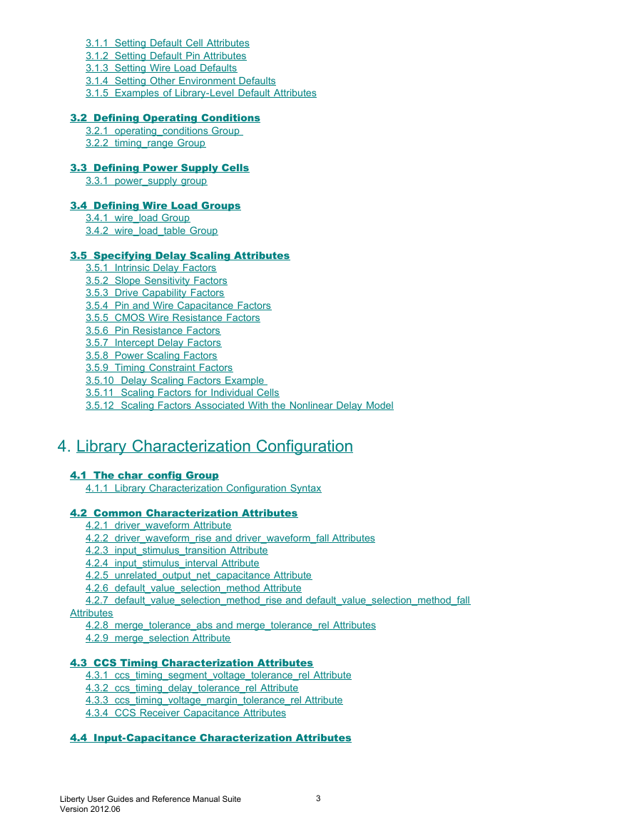
3.1.1 Setting Default Cell Attributes 3.1.2 Setting Default Pin Attributes 3.1.3 Setting Wire Load Defaults 3.1.4 Setting Other Environment Defaults 3.1.5 Examples of Library-Level Default Attributes 3.2 Defining Operating Conditions 3.2.1 operating_conditions Group 3.2.2 timing_range Group 3.3 Defining Power Supply Cells 3.3.1 power_supply group 3.4 Defining Wire Load Groups 3.4.1 wire_load Group 3.4.2 wire_load_table Group 3.5 Specifying Delay Scaling Attributes 3.5.1 Intrinsic Delay Factors 3.5.2 Slope Sensitivity Factors 3.5.3 Drive Capability Factors 3.5.4 Pin and Wire Capacitance Factors 3.5.5 CMOS Wire Resistance Factors 3.5.6 Pin Resistance Factors 3.5.7 Intercept Delay Factors 3.5.8 Power Scaling Factors 3.5.9 Timing Constraint Factors 3.5.10 Delay Scaling Factors Example 3.5.11 Scaling Factors for Individual Cells 3.5.12 Scaling Factors Associated With the Nonlinear Delay Model 4. Library Characterization Configuration 4.1 The char_config Group 4.1.1 Library Characterization Configuration Syntax 4.2 Common Characterization Attributes 4.2.1 driver_waveform Attribute 4.2.2 driver_waveform_rise and driver_waveform_fall Attributes 4.2.3 input_stimulus_transition Attribute 4.2.4 input_stimulus_interval Attribute 4.2.5 unrelated_output_net_capacitance Attribute 4.2.6 default_value_selection_method Attribute 4.2.7 default_value_selection_method_rise and default_value_selection_method_fall Attributes 4.2.8 merge_tolerance_abs and merge_tolerance_rel Attributes 4.2.9 merge_selection Attribute 4.3 CCS Timing Characterization Attributes 4.3.1 ccs_timing_segment_voltage_tolerance_rel Attribute 4.3.2 ccs_timing_delay_tolerance_rel Attribute 4.3.3 ccs_timing_voltage_margin_tolerance_rel Attribute 4.3.4 CCS Receiver Capacitance Attributes 4.4 Input-Capacitance Characterization Attributes Liberty User Guides and Reference Manual Suite Version 2012.063
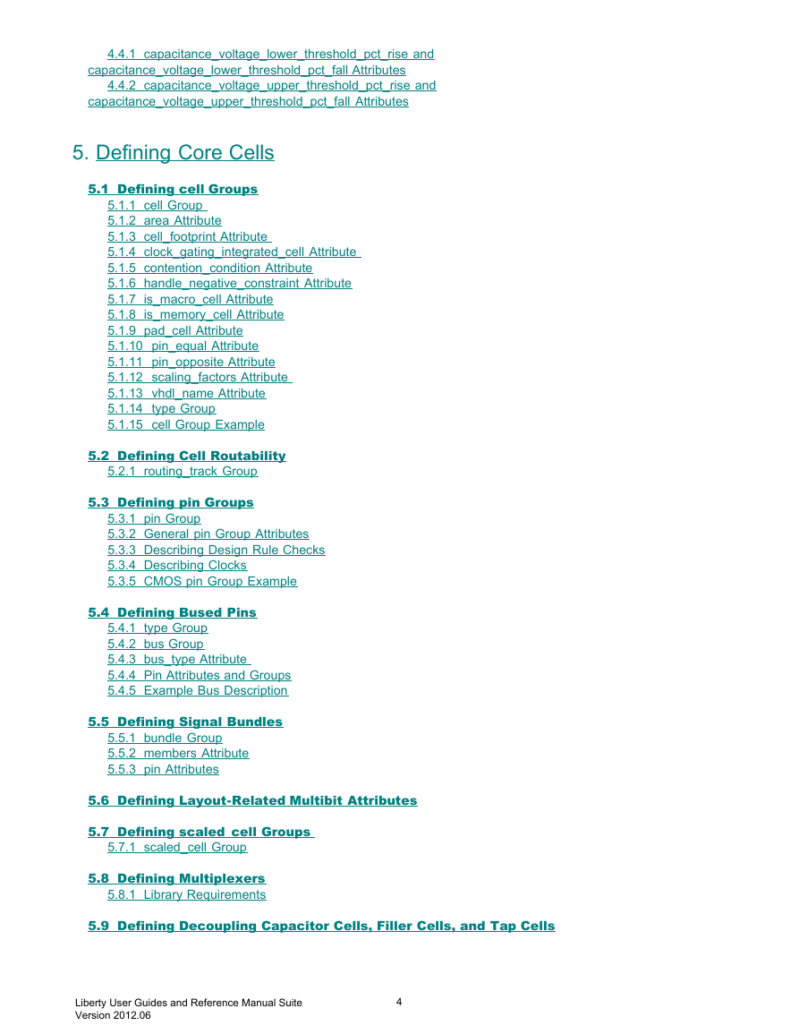
4.4.1 capacitance_voltage_lower_threshold_pct_rise and capacitance_voltage_lower_threshold_pct_fall Attributes 4.4.2 capacitance_voltage_upper_threshold_pct_rise and capacitance_voltage_upper_threshold_pct_fall Attributes 5. Defining Core Cells 5.1 Defining cell Groups 5.1.1 cell Group 5.1.2 area Attribute 5.1.3 cell_footprint Attribute 5.1.4 clock_gating_integrated_cell Attribute 5.1.5 contention_condition Attribute 5.1.6 handle_negative_constraint Attribute 5.1.7 is_macro_cell Attribute 5.1.8 is_memory_cell Attribute 5.1.9 pad_cell Attribute 5.1.10 pin_equal Attribute 5.1.11 pin_opposite Attribute 5.1.12 scaling_factors Attribute 5.1.13 vhdl_name Attribute 5.1.14 type Group 5.1.15 cell Group Example 5.2 Defining Cell Routability 5.2.1 routing_track Group 5.3 Defining pin Groups 5.3.1 pin Group 5.3.2 General pin Group Attributes 5.3.3 Describing Design Rule Checks 5.3.4 Describing Clocks 5.3.5 CMOS pin Group Example 5.4 Defining Bused Pins 5.4.1 type Group 5.4.2 bus Group 5.4.3 bus_type Attribute 5.4.4 Pin Attributes and Groups 5.4.5 Example Bus Description 5.5 Defining Signal Bundles 5.5.1 bundle Group 5.5.2 members Attribute 5.5.3 pin Attributes 5.6 Defining Layout-Related Multibit Attributes 5.7 Defining scaled_cell Groups 5.7.1 scaled_cell Group 5.8 Defining Multiplexers 5.8.1 Library Requirements 5.9 Defining Decoupling Capacitor Cells, Filler Cells, and Tap Cells Liberty User Guides and Reference Manual Suite Version 2012.064
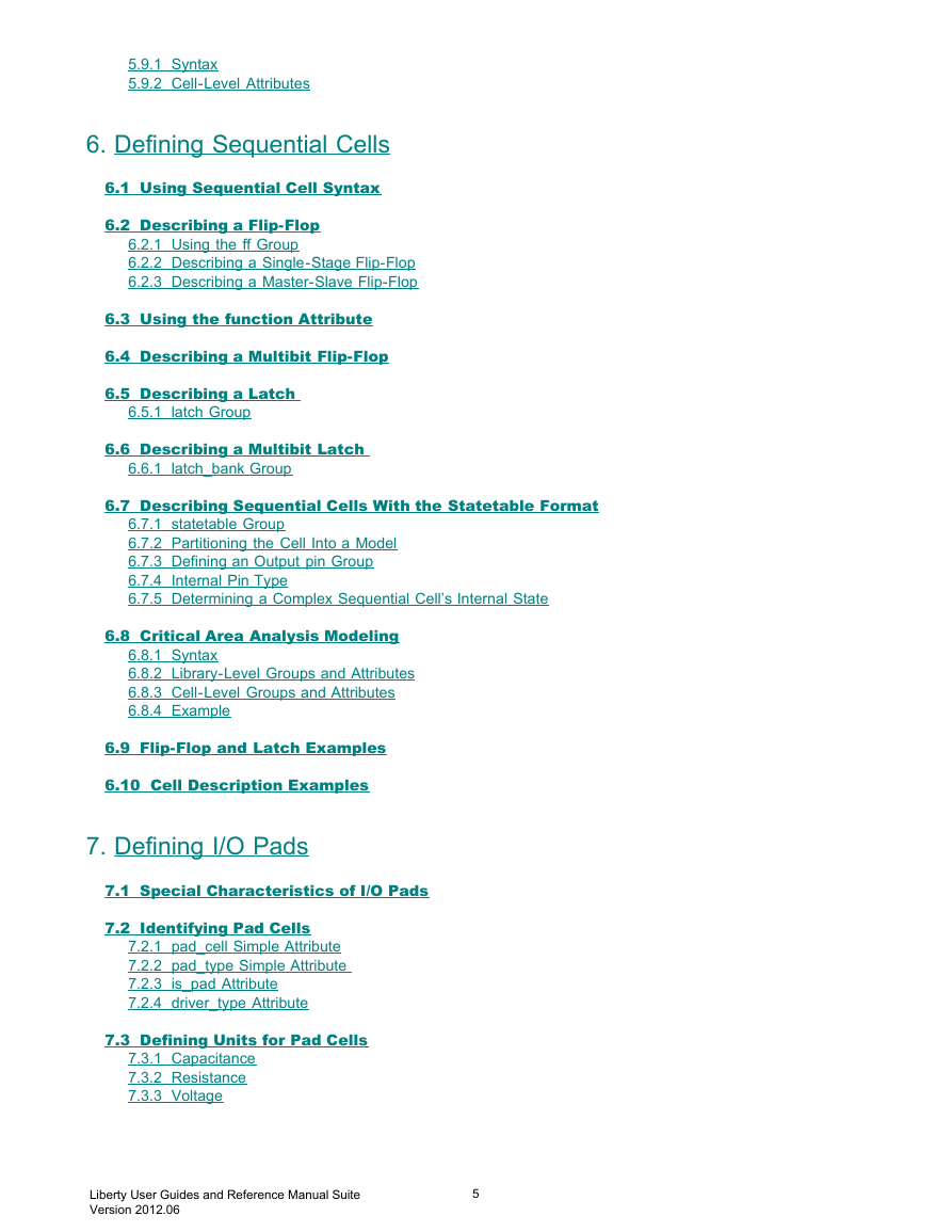
5.9.1 Syntax 5.9.2 Cell-Level Attributes 6. Defining Sequential Cells 6.1 Using Sequential Cell Syntax 6.2 Describing a Flip-Flop 6.2.1 Using the ff Group 6.2.2 Describing a Single-Stage Flip-Flop 6.2.3 Describing a Master-Slave Flip-Flop 6.3 Using the function Attribute 6.4 Describing a Multibit Flip-Flop 6.5 Describing a Latch 6.5.1 latch Group 6.6 Describing a Multibit Latch 6.6.1 latch_bank Group 6.7 Describing Sequential Cells With the Statetable Format 6.7.1 statetable Group 6.7.2 Partitioning the Cell Into a Model 6.7.3 Defining an Output pin Group 6.7.4 Internal Pin Type 6.7.5 Determining a Complex Sequential Cell’s Internal State 6.8 Critical Area Analysis Modeling 6.8.1 Syntax 6.8.2 Library-Level Groups and Attributes 6.8.3 Cell-Level Groups and Attributes 6.8.4 Example 6.9 Flip-Flop and Latch Examples 6.10 Cell Description Examples 7. Defining I/O Pads 7.1 Special Characteristics of I/O Pads 7.2 Identifying Pad Cells 7.2.1 pad_cell Simple Attribute 7.2.2 pad_type Simple Attribute 7.2.3 is_pad Attribute 7.2.4 driver_type Attribute 7.3 Defining Units for Pad Cells 7.3.1 Capacitance 7.3.2 Resistance 7.3.3 Voltage Liberty User Guides and Reference Manual Suite Version 2012.065
7.3.4 Current 7.4 Describing Input Pads 7.4.1 input_voltage Group 7.4.2 hysteresis Attribute 7.5 Describing Output Pads 7.5.1 output_voltage Group 7.5.2 Drive Current 7.5.3 Slew-Rate Control 7.6 Modeling Wire Load for Pads 7.7 Programmable Driver Type Support in I/O Pad Cell Models 7.7.1 Syntax 7.7.2 Programmable Driver Type Functions 7.8 Pad Cell Examples 7.8.1 Input Pads 7.8.2 Output Pads 7.8.3 Bidirectional Pad 7.8.4 Cell with contention_condition and x_function 8. Defining Test Cells 8.1 Describing a Scan Cell 8.1.1 test_cell Group 8.1.2 test_output_only Attribute 8.1.3 signal_type Simple Attribute 8.2 Describing a Multibit Scan Cell 8.2.1 Describing a Multibit Scan Sequential-Elements Cell 8.3 Scan Cell Modeling Examples 8.3.1 Simple Multiplexed D Flip-Flop 8.3.2 Multibit Cells With Multiplexed D Flip-Flop and Enable 8.3.3 LSSD Scan Cell 8.3.4 Scan-Enabled LSSD Cell 8.3.5 Clocked-Scan Test Cell 8.3.6 Scan D Flip-Flop With Auxiliary Clock 9. Advanced Low-Power Modeling 9.1 Power and Ground (PG) Pins 9.1.1 Partial PG Pin Cell Modeling 9.1.2 PG Pin Syntax 9.1.3 Library-Level Attributes 9.1.4 Cell-Level Attributes 9.1.5 Pin-Level Attributes 9.1.6 Standard Cell With One Power and Ground Pin Example 9.1.7 Inverter With Substrate-Bias Pins Example 9.2 Level-Shifter Cells in a Multivoltage Design Liberty User Guides and Reference Manual Suite Version 2012.066
9.2.1 Operating Voltages 9.2.2 Level Shifter Functionality 9.2.3 Basic Level-Shifter Syntax 9.2.4 Cell-Level Attributes 9.2.5 Pin-Level Attributes 9.2.6 Enable Level-Shifter Cell 9.2.7 Level Shifter Modeling Examples 9.3 Isolation Cell Modeling 9.3.1 Cell-Level Attribute 9.3.2 Pin-Level Attributes 9.3.3 Isolation Cell Example 9.3.4 Clamping Isolation Cell Output Pins 9.3.5 Isolation Cells With Multiple Control Pins 9.4 Macro Cell Modeling 9.4.1 Macro Cell Isolation Modeling 9.4.2 Modeling Macro Cells With Internal PG Pins 9.5 Switch Cell Modeling 9.5.1 Coarse-Grain Switch Cells 9.5.2 Fine-Grained Switch Support for Macro Cells 9.5.3 Switch-Cell Modeling Examples 9.6 Retention Cell Modeling 9.6.1 Modes of Operation 9.6.2 Retention Cell Modeling Syntax 9.6.3 Cell-Level Attributes, Groups, and Variables 9.6.4 Pin-Level Attributes 9.6.5 Retention Cell Model Examples 9.7 Always-On Cell Modeling 9.7.1 Always-On Cell Syntax 9.7.2 always_on Simple Attribute 9.7.3 Always-On Simple Buffer Example 9.7.4 Macro Cell With an Always-On Pin Example 9.8 Modeling Antenna Diodes 9.8.1 Antenna-Diode Cell Modeling 9.8.2 Modeling Cells With Built-In Antenna-Diode Ports 10. Modeling Power and Electromigration 10.1 Modeling Power Terminology 10.1.1 Static Power 10.1.2 Dynamic Power 10.2 Switching Activity 10.3 Modeling for Leakage Power 10.4 Representing Leakage Power Information 10.4.1 cell_leakage_power Simple Attribute 10.4.2 Using the leakage_power Group for a Single Value 10.4.3 Using the leakage_power Group for a Polynomial Liberty User Guides and Reference Manual Suite Version 2012.067
分享到:
收藏