IEEE Std 802.15.4™-2015 Cover
Title page
Important Notices and Disclaimers Concerning IEEE Standards Documents
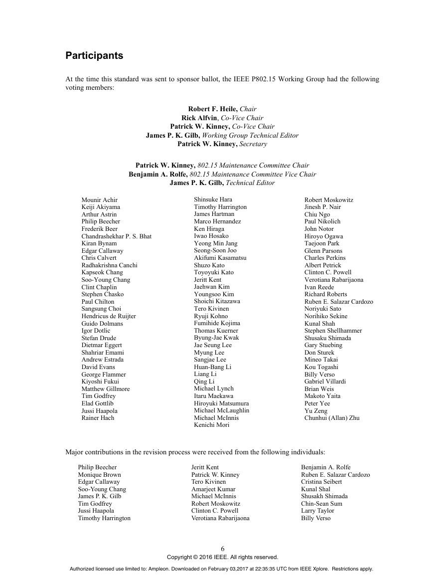
Participants
Historical participants
Introduction
Contents
IMPORTANT NOTICE
1. Overview
1.1 Scope
1.2 Purpose
2. Normative references
3. Definitions, acronyms, and abbreviations
3.1 Definitions
3.2 Acronyms and abbreviations
4. Format conventions
4.1 General
4.2 Fields
4.3 Numbers
4.4 Strings
4.5 Reserved fields and values
5. General description
5.1 Introduction
5.2 Special application spaces
5.2.1 Smart utility network (SUN)
5.2.2 Rail communications and control (RCC)
5.2.3 Television white space (TVWS)
5.2.4 Radio frequency identification (RFID)
5.2.5 Low-energy, critical infrastructure monitoring (LECIM)
5.2.6 Medical body area network (MBAN) services
5.3 Components of the IEEE 802.15.4 WPAN
5.4 Multi-PHY management (MPM) of the SUN WPAN
5.5 Network topologies
5.5.1 Star network formation
5.5.2 Peer-to-peer network formation
5.6 Architecture
5.6.1 PHY
5.6.2 MAC sublayer
5.7 Functional overview
5.7.1 Superframe structure
5.7.1.1 Beacon superframe
5.7.1.2 DSME multi-superframe structure
5.7.1.3 Slotframes
5.7.1.4 TMCTP superframe
5.7.2 Data transfer model
5.7.2.1 Types of data transfer models
5.7.2.2 Data transfer to a coordinator
5.7.2.3 Data transfer from a coordinator
5.7.2.4 Peer-to-peer data transfers
5.7.3 Frame structure
5.7.4 Access methods
5.7.4.1 Frame acknowledgment
5.7.4.2 Frak
5.7.4.3 Data verification
5.7.5 Power consumption considerations
5.7.5.1 Low-energy mechanisms
5.7.6 Security
5.8 Concept of primitives
5.9 Deprecation of features
6. MAC functional description
6.1 Device types and conventions
6.2 Channel access
6.2.1 Superframe structure
6.2.1.1 Contention access period (CAP)
6.2.1.2 Contention-free period (CFP)
6.2.1.3 BOP
6.2.2 Incoming and outgoing superframe timing
6.2.3 Enhanced Beacon frame timing for MPM procedure
6.2.4 IFS
6.2.5 Random access methods
6.2.5.1 CSMA-CA algorithm
6.2.5.2 TSCH CCA algorithm
6.2.5.3 TSCH CSMA-CA retransmission algorithm
6.2.5.4 CSMA-CA with PCA
6.2.5.5 LECIM ALOHA PCA
6.2.6 TSCH slotframe structure
6.2.6.1 General
6.2.6.2 Absolute slot number (ASN)
6.2.6.3 Links
6.2.6.4 Multiple slotframes
6.2.7 LE functional description
6.2.7.1 LE contention access period (LE CAP)
6.2.7.2 LE superframe structure
6.2.7.3 LE-incoming and outgoing superframe timing
6.2.7.4 LE scan
6.2.8 Superframe use for TMCTP operation
6.2.9 Rail communications and control network (RCCN) superframe structure
6.2.10 Channel hopping
6.3 Starting and maintaining PANs
6.3.1 Scanning through channels
6.3.1.1 ED channel scan
6.3.1.2 Active and passive channel scan
6.3.1.3 Orphan channel scan
6.3.1.4 RIT passive channel scan
6.3.2 PAN ID conflict resolution
6.3.2.1 Detection
6.3.2.2 Resolution
6.3.3 Starting and realigning a PAN
6.3.3.1 Starting a PAN
6.3.3.2 Realigning a PAN
6.3.3.3 Realignment in a PAN
6.3.3.4 Updating superframe configuration and channel PIB attributes
6.3.4 Beacon generation
6.3.5 Device discovery
6.3.6 TSCH PAN formation
6.4 Association and disassociation
6.4.1 Association
6.4.2 Disassociation
6.4.3 Fast association
6.5 Synchronization
6.5.1 General
6.5.2 Synchronization with beacons
6.5.3 Synchronization without beacons
6.5.4 Synchronization in TSCH PAN
6.5.4.1 Timeslot communication
6.5.4.2 Node synchronization
6.5.5 Orphaned device realignment
6.6 Transaction handling
6.7 Transmission, reception, and acknowledgment
6.7.1 Transmission
6.7.2 Reception and rejection
6.7.3 Extracting pending data from a coordinator
6.7.4 Use of acknowledgments and retransmissions
6.7.4.1 No acknowledgment
6.7.4.2 Acknowledgment
6.7.4.3 Retransmissions
6.7.5 Transmission timing restrictions
6.7.6 Guard time
6.7.7 Promiscuous mode
6.7.8 Transmission scenarios
6.7.9 Device announcement
6.8 GTS allocation and management
6.8.1 GTS general requirements
6.8.2 CAP maintenance
6.8.3 GTS allocation
6.8.4 GTS usage
6.8.5 GTS deallocation
6.8.6 GTS reallocation
6.8.7 GTS expiration
6.9 Ranging
6.9.1 Ranging requirements
6.9.2 Set-up activities before a ranging exchange
6.9.3 Finish-up activities after a ranging exchange
6.9.4 Managing DPS
6.9.5 The ranging exchange
6.10 PHY parameter change notification procedure
6.10.1 Signaling using Beacon frames
6.10.2 Signaling using multipurpose frames
6.11 Deterministic and synchronous multi-channel extension (DSME)
6.11.1 DSME command requirements
6.11.2 DSME multi-superframe structure
6.11.3 Channel diversity
6.11.3.1 Channel adaptation
6.11.3.2 Channel hopping
6.11.4 CAP reduction
6.11.5 DSME GTS allocation and management
6.11.5.1 DSME GTS allocation
6.11.5.2 DSME GTS deallocation
6.11.5.3 DSME GTS expiration
6.11.5.4 DSME GTS retrieve
6.11.5.5 DSME GTS change
6.11.6 Beacon scheduling
6.11.7 Time synchronization
6.11.8 Deferred beacon
6.11.9 Passive channel scan
6.12 LE transmission, reception and acknowledgment
6.12.1 LE transmission, reception, and acknowledgment with positive handshakes
6.12.2 Coordinated sampled listening (CSL)
6.12.2.1 CSL idle listening
6.12.2.2 CSL transmission
6.12.2.3 Unicast transmission
6.12.2.4 Broadcast transmission
6.12.2.5 CSL reception
6.12.2.6 CSL over multiple channels
6.12.2.7 Turning off CSL mode to reduce latency
6.12.3 RIT
6.12.3.1 General
6.12.3.2 Periodic RIT data request transmission and reception
6.12.3.3 RIT transmission
6.12.4 Implicit RIT (I-RIT)
6.13 Starting and maintaining TMCTPs
6.14 MPM procedure for inter-PHY coexistence
6.15 TVWS access procedures
6.16 Channel timing management (CTM)
7. MAC frame formats
7.1 Device extended address
7.2 General MAC frame format
7.2.1 Frame Control field
7.2.1.1 Frame Type field
7.2.1.2 Security Enabled field
7.2.1.3 Frame Pending field
7.2.1.4 AR field
7.2.1.5 PAN ID Compression field
7.2.1.6 Sequence Number Suppression
7.2.1.7 IE Present field
7.2.1.8 Destination Addressing Mode field
7.2.1.9 Frame Version field
7.2.1.10 Source Addressing Mode field
7.2.2 Sequence Number field
7.2.3 Destination PAN ID field
7.2.4 Destination Address field
7.2.5 Source PAN ID field
7.2.6 Source Address field
7.2.7 Auxiliary Security Header field
7.2.8 IE field
7.2.9 Frame Payload field
7.2.10 FCS field
7.3 Format of individual frame types
7.3.1 Beacon frame format
7.3.1.1 Beacon frame MHR field
7.3.1.2 IEs field
7.3.1.3 Superframe Specification field
7.3.1.4 GTS Info field
7.3.1.5 Pending Address field
7.3.1.6 Beacon Payload field
7.3.2 Data frame format
7.3.2.1 Data frame MHR field
7.3.2.2 Data Payload field
7.3.3 Ack frame format
7.3.4 MAC command frame format
7.3.4.1 MHR field
7.3.4.2 Command ID field
7.3.4.3 Payload field
7.3.5 Multipurpose frame format
7.3.5.1 Frame Type field
7.3.5.2 Long Frame Control field
7.3.5.3 Destination Addressing Mode field
7.3.5.4 Source Addressing Mode field
7.3.5.5 PAN ID Present field
7.3.5.6 Security Enabled field
7.3.5.7 Sequence Number Suppression field
7.3.5.8 Frame Pending field
7.3.5.9 Frame Version field
7.3.5.10 Ack Request field
7.3.5.11 IEs Present field
7.3.5.12 Sequence Number field
7.3.5.13 Destination PAN ID field
7.3.5.14 Destination Address field
7.3.5.15 Source Address field
7.3.5.16 Auxiliary Security Header field
7.3.5.17 IEs field
7.3.5.18 Payload field
7.3.6 Extended frame format
7.4 IEs
7.4.1 IE list termination
7.4.2 Header IEs
7.4.2.1 Header IE format
7.4.2.2 Vendor Specific Header IE
7.4.2.3 CSL IE
7.4.2.4 RIT IE
7.4.2.5 DSME PAN descriptor IE
7.4.2.6 Rendezvous Time IE
7.4.2.7 Time Correction IE
7.4.2.8 Extended DSME PAN descriptor IE
7.4.2.9 Fragment Sequence Context Description (FSCD) IE
7.4.2.10 Simplified Superframe Specification IE
7.4.2.11 Simplified GTS Specification IE
7.4.2.12 LECIM Capabilities IE
7.4.2.13 RCC Capabilities IE
7.4.2.14 RCCN Descriptor IE
7.4.2.15 Global Time IE
7.4.2.16 DA IE
7.4.2.17 Header Termination 1 IE
7.4.2.18 Header Termination 2 IE
7.4.3 Payload IEs
7.4.3.1 Encapsulated Service Data Unit (ESDU) IE
7.4.3.2 MLME IE
7.4.3.3 Payload Termination IE
7.4.4 Nested IE
7.4.4.1 Format of Nested IE
7.4.4.2 TSCH Synchronization IE
7.4.4.3 TSCH Slotframe and Link IE
7.4.4.4 TSCH Timeslot IE
7.4.4.5 Hopping timing IE
7.4.4.6 Enhanced Beacon Filter IE
7.4.4.7 MAC Metrics IE
7.4.4.8 All MAC Metrics IE
7.4.4.9 Coexistence Specification IE
7.4.4.10 SUN Device Capabilities IE
7.4.4.11 SUN FSK Generic PHY IE
7.4.4.12 Mode Switch Parameter IE
7.4.4.13 PHY Parameter Change IE
7.4.4.14 O-QPSK PHY Mode IE
7.4.4.15 PCA Allocation IE
7.4.4.16 LECIM DSSS Operating Mode IE
7.4.4.17 LECIM FSK Operating Mode IE
7.4.4.18 TVWS PHY Operating Mode Description IE
7.4.4.19 TVWS Device Capabilities IE
7.4.4.20 TVWS Device Category IE
7.4.4.21 TVWS Device Identification IE
7.4.4.22 TVWS Device Location IE
7.4.4.23 TVWS Channel Information Query IE
7.4.4.24 TVWS Channel Information Source IE
7.4.4.25 CTM IE
7.4.4.26 Timestamp IE
7.4.4.27 Timestamp Difference IE
7.4.4.28 TMCTP Specification IE
7.4.4.29 RCC PHY Operating Mode IE
7.4.4.30 Vendor Specific Nested IE
7.4.4.31 Channel hopping IE
7.5 MAC commands
7.5.1 Command ID field
7.5.2 Association Request command
7.5.3 Association Response command
7.5.4 Disassociation Notification command
7.5.5 Data Request command
7.5.6 PAN ID Conflict Notification command
7.5.7 Orphan Notification command
7.5.8 Beacon Request command
7.5.9 Enhanced Beacon Request command
7.5.10 Coordinator realignment command
7.5.11 GTS request command
7.5.12 DSME Association Request command
7.5.13 DSME Association Response command
7.5.14 DSME GTS Request command
7.5.15 DSME GTS Response command
7.5.16 DSME GTS Notify command
7.5.17 DSME Information Request command
7.5.18 DSME Information Response command
7.5.19 DSME Beacon Allocation Notification command
7.5.20 DSME Beacon Collision Notification command
7.5.21 DSME Link Report command
7.5.22 RIT Data Request command
7.5.23 DBS Request command
7.5.24 DBS Response command
7.5.25 RIT Data Response command
7.5.26 Vendor Specific command
8. MAC services
8.1 Overview
8.2 MAC management service
8.2.1 Primitives supported by the MLME-SAP interface
8.2.2 Common requirements for MLME primitives
8.2.3 Association primitives
8.2.3.1 MLME-ASSOCIATE.request
8.2.3.2 MLME-ASSOCIATE.indication
8.2.3.3 MLME-ASSOCIATE.response
8.2.3.4 MLME-ASSOCIATE.confirm
8.2.4 Disassociation primitives
8.2.4.1 MLME-DISASSOCIATE.request
8.2.4.2 MLME-DISASSOCIATE.indication
8.2.4.3 MLME-DISASSOCIATE.confirm
8.2.5 Communications notification primitives
8.2.5.1 MLME-BEACON-NOTIFY.indication
8.2.5.2 MLME-COMM-STATUS.indication
8.2.5.3 MLME-IE-NOTIFY.indication
8.2.6 Primitives for reading and writing PIB attributes
8.2.6.1 MLME-GET.request
8.2.6.2 MLME-GET.confirm
8.2.6.3 MLME-SET.request
8.2.6.4 MLME-SET.confirm
8.2.7 GTS management primitives
8.2.7.1 MLME-GTS.request
8.2.7.2 MLME-GTS.confirm
8.2.7.3 MLME-GTS.indication
8.2.8 Primitives for orphan notification
8.2.8.1 MLME-ORPHAN.indication
8.2.8.2 MLME-ORPHAN.response
8.2.9 Primitives for resetting the MAC sublayer
8.2.9.1 MLME-RESET.request
8.2.9.2 MLME-RESET.confirm
8.2.10 Primitives for specifying the receiver enable time
8.2.10.1 MLME-RX-ENABLE.request
8.2.10.2 MLME-RX-ENABLE.confirm
8.2.11 Primitives for channel scanning
8.2.11.1 MLME-SCAN.request
8.2.11.2 MLME-SCAN.confirm
8.2.12 Primitives for updating the superframe configuration
8.2.12.1 MLME-START.request
8.2.12.2 MLME-START.confirm
8.2.13 Primitives for synchronizing with a coordinator
8.2.13.1 MLME-SYNC.request
8.2.13.2 MLME-SYNC-LOSS.indication
8.2.14 Primitives for requesting data from a coordinator
8.2.14.1 MLME-POLL.request
8.2.14.2 MLME-POLL.confirm
8.2.15 Primitives for specifying dynamic preamble
8.2.15.1 MLME-DPS.request
8.2.15.2 MLME-DPS.confirm
8.2.15.3 MLME-DPS.indication
8.2.16 Primitives for channel sounding
8.2.16.1 MLME-SOUNDING.request
8.2.16.2 MLME-SOUNDING.confirm
8.2.17 Primitives for ranging calibration
8.2.17.1 MLME-CALIBRATE.request
8.2.17.2 MLME-CALIBRATE.confirm
8.2.18 Primitives for Beacon Generation
8.2.18.1 MLME-BEACON.request
8.2.18.2 MLME-BEACON.confirm
8.2.18.3 MLME-BEACON-REQUEST.indication
8.2.19 Primitives for TSCH
8.2.19.1 MLME-SET-SLOTFRAME.request
8.2.19.2 MLME-SET-SLOTFRAME.confirm
8.2.19.3 MLME-SET-LINK.request
8.2.19.4 MLME-SET-LINK.confirm
8.2.19.5 MLME-TSCH-MODE.request
8.2.19.6 MLME-TSCH-MODE.confirm
8.2.19.7 MLME-KEEP-ALIVE.request
8.2.19.8 MLME-KEEP-ALIVE.confirm
8.2.20 Primitives for DSME GTS management
8.2.20.1 MLME-DSME-GTS.request
8.2.20.2 MLME-DSME-GTS.indication
8.2.20.3 MLME-DSME-GTS.response
8.2.20.4 MLME-DSME-GTS.confirm
8.2.21 Primitives for reporting the link status
8.2.21.1 MLME-DSME-LINK-REPORT.request
8.2.21.2 MLME-DSME-LINK-REPORT.indication
8.2.21.3 MLME-DSME-LINK-REPORT.confirm
8.2.22 Operating parameter change primitives
8.2.22.1 MLME-PHY-OP-SWITCH.request
8.2.22.2 MLME-PHY-OP-SWITCH.indication
8.2.22.3 MLME-PHY-OP-SWITCH.confirm
8.2.23 TMCTP DBS allocation primitives
8.2.23.1 MLME-DBS.request
8.2.23.2 MLME-DBS.indication
8.2.23.3 MLME-DBS.response
8.2.23.4 MLME-DBS.confirm
8.2.24 Primitives for device announcement
8.2.24.1 MLME-DA.request primitive
8.2.24.2 MLME-DA.indication primitive
8.2.24.3 MLME-DA.confirm primitive
8.2.25 RIT data commands
8.2.25.1 MLME-RIT-REQ.indication
8.2.25.2 MLME-RIT-RES.request
8.2.25.3 MLME-RIT-RES.indication
8.2.25.4 MLME-RIT-RES.confirm
8.3 MAC data service
8.3.1 MCPS-DATA.request
8.3.2 MCPS-DATA.confirm
8.3.3 MCPS-DATA.indication
8.3.4 MCPS-PURGE.request
8.3.5 MCPS-PURGE.confirm
8.4 MAC constants and PIB attributes
8.4.1 MAC constants
8.4.2 MAC PIB attributes
8.4.2.1 General MAC PIB attributes for functional organization
8.4.2.2 TSCH-specific MAC PIB attributes
8.4.2.2.1 TSCH MAC PIB attributes for macSlotframeTable
8.4.2.2.2 TSCH MAC PIB attributes for macLinkTable
8.4.2.2.3 TSCH MAC PIB attributes for macTimeslotTemplate
8.4.2.3 MAC PIB attributes for hopping sequence
8.4.2.4 DSME specific MAC PIB attributes
8.4.2.5 LE specific MAC PIB attributes
8.4.2.6 MAC performance metrics specific MAC PIB attributes
8.4.2.7 Enhanced Beacon Request command specific MAC PIB attributes
8.4.2.8 Enhanced Beacon frame specific MAC PIB attributes
9. Security
9.1 Overview
9.2 Functional description
9.2.1 Outgoing frame security procedure
9.2.2 KeyDescriptor lookup procedure
9.2.3 Incoming frame security procedure, Security Enabled field is set to one
9.2.4 Incoming frame security procedure, Security Enabled field is set to zero
9.2.5 DeviceDescriptor lookup procedure
9.2.6 SecurityLevelDescriptor lookup procedure
9.2.7 Incoming IE security level checking procedure
9.2.8 Incoming IE key usage policy checking procedure
9.2.9 Incoming security level checking procedure
9.2.10 Incoming key usage policy checking procedure
9.3 Security operations
9.3.1 Integer and octet representation
9.3.2 CCM* nonce
9.3.2.1 CCM* nonce for non-TSCH mode
9.3.2.2 CCM* nonce for TSCH mode
9.3.2.3 CCM* nonce for Fragment frames
9.3.3 CCM* prerequisites
9.3.4 CCM* transformation data representation
9.3.4.1 Key and nonce data inputs
9.3.4.2 a data and m data
9.3.4.3 c data output
9.3.5 CCM* inverse transformation data representation
9.3.5.1 Key and nonce data inputs
9.3.5.2 c data and a data
9.3.5.3 m data output
9.4 Auxiliary security header
9.4.1 Security Control field
9.4.1.1 Security Level field
9.4.1.2 Key Identifier Mode field
9.4.1.3 Frame Counter Suppression field
9.4.1.4 ASN in Nonce
9.4.2 Frame Counter field
9.4.3 Key Identifier field
9.4.3.1 Key Source field
9.4.3.2 Key Index field
9.5 Security-related MAC PIB attributes
10. General PHY requirements
10.1 General requirements and definitions
10.1.1 Operating frequency range
10.1.2 Channel assignments
10.1.2.1 Channel numbering for 780 MHz band
10.1.2.2 Channel numbering for 868 MHz, 915 MHz, and 2450 MHz bands
10.1.2.3 Channel numbering for CSS PHY
10.1.2.4 Channel numbering for HRP UWB PHY
10.1.2.5 Channel numbering for MSK PHY 433 MHz band
10.1.2.6 Channel numbering for MSK PHY 2450 MHz band
10.1.2.7 Channel numbering for LRP UWB PHY
10.1.2.8 Channel numbering for SUN and TVWS PHYs
10.1.2.9 Channel numbering for 2380 MHz band
10.1.2.10 Channel numbering for LECIM PHYs
10.1.2.10.1 Channel numbering for LECIM DSSS PHY
10.1.2.10.2 Channel numbering for LECIM FSK PHY
10.1.2.11 Channel numbering for RCC PHYs
10.1.3 Minimum LIFS and SIFS periods
10.1.4 RF power measurement
10.1.5 Transmit power
10.1.6 Out-of-band spurious emission
10.1.7 Receiver sensitivity definitions
10.1.8 Common signaling mode (CSM) for SUN PHY
10.2 General radio specifications
10.2.1 TX-to-RX turnaround time
10.2.2 RX-to-TX turnaround time
10.2.3 Error-vector magnitude (EVM) definition
10.2.4 Receiver maximum input level of desired signal
10.2.5 Receiver ED
10.2.6 Link quality indicator (LQI)
10.2.7 Clear channel assessment (CCA)
11. PHY services
11.1 Overview
11.2 PHY constants
11.3 PHY PIB attributes
12. O-QPSK PHY
12.1 PPDU format
12.1.1 SHR field format
12.1.1.1 Preamble field
12.1.1.2 SFD field
12.1.2 PHR field format
12.1.2.1 Frame Length field
12.1.2.2 PHY Payload field
12.2 Modulation and spreading
12.2.1 Data rate
12.2.2 Reference modulator diagram
12.2.3 Bit-to-symbol mapping
12.2.4 Symbol-to-chip mapping
12.2.5 O-QPSK modulation
12.2.6 Pulse shape
12.2.7 Chip transmission order
12.3 O-QPSK PHY RF requirements
12.3.1 Operating frequency range
12.3.2 Transmit power spectral density (PSD) mask
12.3.3 Symbol rate
12.3.4 Receiver sensitivity
12.3.5 Receiver interference rejection
12.3.6 TX-to-RX turnaround time
12.3.7 RX-to-TX turnaround time
12.3.8 EVM
12.3.9 Transmit center frequency tolerance
12.3.10 Transmit power
12.3.11 Receiver maximum input level of desired signal
12.3.12 Receiver ED
12.3.13 LQI
13. Binary phase-shift keying (BPSK) PHY
13.1 PPDU format
13.2 Modulation and spreading
13.2.1 BPSK PHY data rates
13.2.2 Reference modulator
13.2.3 Differential encoding
13.2.4 Bit-to-chip mapping
13.2.5 BPSK modulation
13.2.5.1 Pulse shape
13.2.5.2 Chip transmission order
13.3 BPSK PHY RF requirements
13.3.1 Operating frequency range
13.3.2 915 MHz band transmit PSD mask
13.3.3 Symbol rate
13.3.4 Receiver sensitivity
13.3.5 Receiver interference rejection
13.3.6 TX-to-RX turnaround time
13.3.7 RX-to-TX turnaround time
13.3.8 EVM
13.3.9 Transmit center frequency tolerance
13.3.10 Transmit power
13.3.11 Receiver maximum input level of desired signal
13.3.12 Receiver ED
13.3.13 LQI
14. Amplitude shift keying (ASK) PHY
14.1 Status of ASK PHY
14.2 PPDU format
14.2.1 Preamble field for ASK PHY
14.2.2 SFD for ASK PHY
14.3 Modulation and spreading
14.3.1 ASK PHY data rates
14.3.2 Reference modulator
14.3.3 Bit-to-symbol mapping
14.3.4 Symbol-to-chip mapping
14.3.5 ASK modulation
14.3.6 Pulse shape
14.3.7 Chip transmission order
14.4 ASK PHY RF requirements
14.4.1 Operating frequency range
14.4.2 915 MHz band transmit PSD mask
14.4.3 Symbol rate
14.4.4 Receiver sensitivity
14.4.5 Receiver interference rejection
14.4.6 TX-to-RX turnaround time
14.4.7 RX-to-TX turnaround time
14.4.8 EVM
14.4.9 Transmit center frequency tolerance
14.4.10 Transmit power
14.4.11 Receiver maximum input level of desired signal
14.4.12 Receiver ED
14.4.13 LQI
14.4.14 Example of PSSS encoding
15. Chirp spread spectrum (CSS) PHY
15.1 CSS PPDU format
15.1.1 Preamble field
15.1.2 SFD field
15.1.3 PHR field
15.1.4 PHY Payload field
15.2 Modulation and spreading
15.2.1 Data rates
15.2.2 Reference modulator
15.2.3 De-multiplexer (DEMUX)
15.2.4 Serial-to-parallel mapping
15.2.5 Data-symbol-to-bi-orthogonal-codeword mapping
15.2.6 Parallel-to-serial converter and QPSK symbol mapping
15.2.7 DQPSK coding
15.2.8 DQPSK-to-DQCSK modulation
15.2.9 CSK generator
15.2.10 Bit interleaver
15.3 Waveform and subchirp sequences
15.3.1 Graphical presentation of chirp symbols (subchirp sequences)
15.3.2 Active usage of time gaps
15.3.3 Mathematical representation of the continuous time CSS base-band signal
15.3.4 Raised cosine window for chirp pulse shaping
15.3.5 Subchirp transmission order
15.3.6 Example of CSK signal generation
15.4 CSS RF requirements
15.4.1 Transmit power spectral density (PSD) mask and signal tolerance
15.4.2 Symbol rate
15.4.3 Receiver sensitivity
15.4.4 Receiver interference rejection
15.4.5 TX-to-RX turnaround time
15.4.6 RX-to-TX turnaround time
15.4.7 Transmit center frequency tolerance
15.4.8 Transmit power
15.4.9 Receiver maximum input level of desired signal
15.4.10 Receiver ED
15.4.11 LQI
16. HRP UWB PHY
16.1 General
16.2 HRP UWB PPDU format
16.2.1 PPDU encoding process
16.2.2 Symbol structure
16.2.3 PSDU timing parameters
16.2.4 Preamble timing parameters
16.2.5 SHR field
16.2.5.1 SYNC field
16.2.5.2 SFD field
16.2.6 PHR field
16.2.7 PHY Payload field
16.3 Modulation
16.3.1 Modulation mathematical framework
16.3.2 Spreading
16.3.3 FEC
16.3.3.1 Reed-Solomon encoding
16.3.3.2 Systematic convolutional encoding
16.4 RF requirements
16.4.1 Operating frequency bands
16.4.2 Channel assignments
16.4.3 Regulatory compliance
16.4.4 Operating temperature range
16.4.5 Baseband impulse response
16.4.6 Transmit PSD mask
16.4.7 Chip rate clock and chip carrier alignment
16.4.8 TX-to-RX turnaround time
16.4.9 RX-to-TX turnaround time
16.4.10 Transmit center frequency tolerance
16.4.11 Receiver maximum input level of desired signal
16.4.12 Receiver ED
16.4.13 LQI
16.4.14 CCA
16.5 HRP UWB PHY optional pulse shapes
16.5.1 HRP UWB PHY optional chirp on UWB (CoU) pulses
16.5.2 HRP UWB PHY optional continuous spectrum (CS) pulses
16.5.3 HRP UWB PHY linear combination of pulses (LCP)
16.6 Extended preamble for optional CCA mode 6
16.7 Ranging
16.7.1 Ranging counter
16.7.2 Crystal characterization
16.7.2.1 Ranging tracking offset
16.7.2.2 Ranging tracking interval
16.7.3 Ranging FoM
17. GFSK PHY
17.1 PPDU formats
17.2 Modulation
17.2.1 GFSK PHY data rates
17.2.2 Reference modulator diagram
17.2.3 Data whitening
17.2.4 GFSK modulation
17.3 GFSK PHY RF requirements
17.3.1 Operating frequency range
17.3.2 Transmit PSD mask
17.3.3 Symbol rate
17.3.4 Receiver sensitivity
17.3.5 Receiver interference rejection
17.3.6 TX-to-RX turnaround time
17.3.7 RX-to-TX turnaround time
17.3.8 Transmit center frequency tolerance
17.3.9 Transmit power
17.3.10 Receiver maximum input level of desired signal
17.3.11 Receiver ED
17.3.12 LQI
18. MSK PHY
18.1 PPDU formats
18.2 Data rate
18.3 SFD for the MSK PHY
18.4 MSK modulation
18.4.1 Reference modulator diagram
18.4.2 Data whitening
18.4.3 Bit-to-symbol mapping
18.4.4 Signal modulation
18.5 MSK PHY requirements
18.5.1 Operating frequency range
18.5.2 Transmit PSD mask
18.5.3 Symbol rate
18.5.4 Transmit center frequency tolerance
18.5.5 Transmit power
18.5.6 Receiver maximum input level of desired signal
18.5.7 Modulation frequency deviation tolerance
18.5.8 Zero crossing tolerance
19. LRP UWB PHY specification
19.1 Overview
19.2 LRP UWB PHY symbol structure
19.2.1 Base mode LRP UWB PHY symbol structure
19.2.1.1 Base mode LRP UWB PHY PSDU synchronization signal
19.2.2 Extended mode LRP UWB PHY symbol structure
19.2.2.1 Extended mode LRP UWB PHY PSDU synchronization signal
19.2.3 Long-range mode LRP UWB PHY symbol structure
19.2.3.1 Long-range mode LRP UWB PHY PSDU synchronization signal
19.3 LRP UWB SHR
19.3.1 LRP UWB SHR preamble
19.3.1.1 LRP UWB base mode SHR preamble
19.3.1.2 RP UWB extended mode SHR preamble
19.3.1.3 LRP UWB long-range mode SHR preamble
19.3.2 LRP UWB SHR SFD
19.4 LRP UWB PHR
19.4.1 Encoding Type field
19.4.2 Header Extension field
19.4.3 SECDED field
19.4.4 Frame Length field
19.4.5 LEIP Length field
19.4.6 LEIP Position field
19.5 LRP UWB PSDU
19.6 LRP UWB location enhancing information postamble
19.7 LRP UWB transmitter specification
19.7.1 Pulse shape
19.7.2 Pulse timing
19.7.3 Transmit PSD mask
19.8 LRP UWB receiver specification
20. SUN FSK PHY
20.1 Introduction
20.2 PPDU format for SUN FSK
20.2.1 SHR field format
20.2.1.1 Preamble field
20.2.1.2 SFD
20.2.2 PHR field format
20.2.3 Mode Switch PHR
20.2.4 PHY Payload field
20.3 Modulation and coding for SUN FSK
20.3.1 Reference modulator
20.3.2 Bit-to-symbol mapping
20.3.3 Modulation quality
20.3.3.1 Frequency deviation tolerance
20.3.3.2 Zero crossing tolerance
20.3.4 FEC
20.3.5 Code-symbol interleaving
20.4 Data whitening for SUN FSK
20.5 Mode switch mechanism for SUN FSK
20.6 SUN FSK PHY RF requirements
20.6.1 Operating frequency range
20.6.2 Regulatory compliance
20.6.3 Radio frequency tolerance
20.6.4 Channel switch time
20.6.5 Transmitter symbol rate
20.6.6 Transmit spectral mask
20.6.7 Receiver sensitivity
20.6.8 Receiver interference rejection
20.6.9 TX-to-RX turnaround time
20.6.10 RX-to-TX turnaround time
20.6.11 Transmit power
20.6.12 Receiver maximum input level of desired signal
20.6.13 Receiver ED
20.6.14 LQI
21. SUN OFDM PHY
21.1 Introduction
21.2 PPDU format for SUN OFDM
21.2.1 Short Training field (STF)
21.2.1.1 Frequency domain STF
21.2.1.2 Time domain STF generation
21.2.1.3 Time domain STF repetition
21.2.1.4 STF normalization
21.2.2 Long Training field (LTF)
21.2.2.1 Frequency domain LTF
21.2.2.2 Time domain LTF generation
21.2.2.3 LTF normalization
21.2.3 PHR
21.2.4 PSDU field
21.3 Data rates for SUN OFDM
21.4 Modulation and coding for SUN OFDM
21.4.1 Reference modulator diagram
21.4.2 Bit-to-symbol mapping
21.4.3 PIB attribute values for phySymbolsPerOctet
21.4.4 FEC
21.4.5 Interleaver
21.4.6 Frequency spreading
21.4.6.1 Frequency spreading by 2x
21.4.6.2 Frequency spreading by 4x
21.4.6.3 No spreading
21.4.7 Pilot tones/null tones
21.4.8 Cyclic prefix (CP)
21.4.9 PPDU Tail field
21.4.10 Pad field
21.4.11 Scrambler and scrambler seeds
21.5 SUN OFDM PHY RF requirements
21.5.1 Operating frequency range
21.5.2 Transmit power spectral density (PSD) mask
21.5.3 Receiver sensitivity
21.5.4 Adjacent channel rejection
21.5.5 Alternate channel rejection
21.5.6 TX-to-RX turnaround time
21.5.7 RX-to-TX turnaround time
21.5.8 EVM definition
21.5.9 Transmit center frequency and symbol tolerance
21.5.10 Transmit power
21.5.11 Receiver maximum input level of desired signal
21.5.12 Receiver ED
21.5.13 LQI
22. SUN O-QPSK PHY
22.1 Introduction
22.2 PPDU format for SUN O-QPSK
22.2.1 SHR field format
22.2.1.1 Preamble field format
22.2.1.2 SFD field format
22.2.2 PHR field format
22.2.3 PHY Payload field
22.3 Modulation and coding for SUN O-QPSK
22.3.1 Reference modulator
22.3.2 SHR coding and spreading
22.3.3 PHR coding and spreading
22.3.4 PSDU coding and spreading for DSSS
22.3.5 PSDU coding and spreading for MDSSS
22.3.6 FEC
22.3.7 Code-bit interleaving
22.3.8 Bit differential encoding (BDE)
22.3.9 DSSS bit-to-chip mapping
22.3.10 MDSSS bit-to-chip mapping
22.3.11 Chip whitening
22.3.12 Pilot insertion
22.3.13 Modulation parameters for O-QPSK
22.4 Support of legacy devices of the 780 MHz, 915 MHz, and 2450 MHz O-QPSK PHYs
22.5 SUN O-QPSK PHY RF requirements
22.5.1 Operating frequency range
22.5.2 Transmit power spectral density (PSD) mask
22.5.3 Receiver sensitivity
22.5.4 Adjacent channel rejection
22.5.5 TX-to-RX turnaround time
22.5.6 RX-to-TX turnaround time
22.5.7 EVM definition
22.5.8 Transmit center frequency and symbol tolerance
22.5.9 Transmit power
22.5.10 Receiver maximum input level of desired signal
22.5.11 Receiver ED
22.5.12 LQI
22.5.13 CCA
23. LECIM DSSS PHYs
23.1 PPDU format for DSSS
23.2 Modulation and spreading
23.2.1 Data rate
23.2.2 Reference modulator diagram
23.2.3 Convolutional FEC encoding
23.2.4 Interleaver
23.2.4.1 256-bit fragment size
23.2.4.2 384-bit fragment size
23.2.4.3 512-bit fragment size
23.2.5 Differential encoding
23.2.6 Bit-to-symbol and symbol-to-chip encoding
23.2.6.1 Gold code generator
23.2.6.2 Orthogonal variable spreading factor (OVSF) code generator
23.2.7 BPSK/O-QPSK modulation
23.2.7.1 BPSK modulation
23.2.7.2 O-QPSK modulation
23.3 PSDU fragmentation
23.3.1 Configuration
23.3.2 Fragmentation
23.3.3 Fragment packet
23.3.4 Calculating FICS field using MIC
23.3.5 Fragment acknowledgment and retransmission
23.3.6 Frak
23.3.6.1 Frak policy
23.3.6.2 Frak format
23.3.7 Reassembly
23.4 DSSS PHY RF requirements
23.4.1 Radio frequency tolerance
23.4.2 Channel switch time
23.4.3 Transmit spectral mask
23.4.4 Receiver sensitivity
23.4.5 Receiver interference rejection
23.4.6 TX-to-RX turnaround time
23.4.7 RX-to-TX turnaround time
23.4.8 Transmit power
24. LECIM FSK PHY specification
24.1 General
24.2 PPDU format for LECIM FSK PHY
24.2.1 SHR field format
24.2.1.1 Preamble field format
24.2.1.2 SFD field format
24.2.2 PHR field format
24.2.3 PHY Payload field
24.3 Modulation and coding for LECIM FSK PHY
24.3.1 Reference modulator
24.3.2 Bit-to-symbol mapping
24.3.3 Modulation quality
24.3.3.1 Frequency deviation tolerance
24.3.3.2 Zero crossing tolerance
24.3.4 FEC
24.3.5 Code-bit interleaving
24.3.6 Spreading
24.4 Data whitening for LECIM FSK PHY
24.5 LECIM FSK PHY RF requirements
24.5.1 Operating frequency range
24.5.2 Radio frequency tolerance
24.5.3 Channel switch time
24.5.4 Transmit spectral mask
24.5.5 Receiver sensitivity
24.5.6 TX-to-RX turnaround time
24.5.7 RX-to-TX turnaround time
24.5.8 Transmit power
25. TVWS-FSK PHY
25.1 PPDU format for TVWS-FSK
25.1.1 SHR field format
25.1.1.1 Preamble field format
25.1.1.2 SFD field format
25.1.2 PHR field format
25.1.3 PHY Payload field
25.2 Modulation and coding for TVWS-FSK
25.2.1 Reference modulator
25.2.2 FEC and interleaving
25.2.3 Data whitening
25.2.4 Spreading
25.2.5 Bit-to-symbol mapping
25.2.6 Modulation quality
25.2.7 Values for phySymbolsPerOctet
25.3 TVWS-FSK RF requirements
25.3.1 Operating frequency range
25.3.2 Clock frequency and timing accuracy
25.3.3 Channel switch time
25.3.4 Receiver sensitivity
25.3.5 TX-to-RX turnaround time
25.3.6 RX-to-TX turnaround time
25.3.7 Receiver maximum input level of desired signal
25.3.8 Receiver ED
25.3.9 LQI
26. TVWS-OFDM PHY
26.1 General
26.2 PPDU format for TVWS-OFDM
26.2.1 STF
26.2.1.1 Frequency domain STF
26.2.1.2 Time domain STF generation
26.2.1.3 Time domain STF repetition
26.2.1.4 STF power boosting
26.2.2 LTF
26.2.2.1 Frequency domain LTF
26.2.2.2 Time domain LTF generation
26.2.3 PHR field format
26.2.4 PSDU field
26.3 System parameters for TVWS-OFDM
26.4 Modulation and coding for TVWS-OFDM
26.4.1 Reference modulator
26.4.2 Bit-to-symbol mapping
26.4.3 FEC
26.4.4 Interleaver
26.4.5 Pilot tones/null tones
26.4.6 CP
26.4.7 PPDU Tail field
26.4.8 Pad field
26.4.9 Scrambler and scrambler seeds
26.5 TVWS-OFDM RF requirements
26.5.1 Operating frequency range
26.5.2 Pulse shaping
26.5.3 Transmit power spectral density (PSD) mask
26.5.4 Receiver sensitivity
26.5.5 TX-to-RX turnaround time
26.5.6 RX-to-TX turnaround time
26.5.7 EVM definition
26.5.8 Transmit center frequency and symbol tolerance
27. TVWS-NB-OFDM PHY
27.1 PPDU format for TVWS-NB-OFDM
27.1.1 Short Training field (STF)
27.1.1.1 Frequency domain STF
27.1.1.2 Time domain STF generation
27.1.1.3 Time domain STF repetition
27.1.1.4 STF normalization
27.1.2 Long training field (LTF)
27.1.2.1 Frequency domain LTF generation
27.1.2.2 Time domain LTF generation
27.1.2.3 Time domain LTF repetition
27.1.2.4 LTF normalization
27.1.3 PHR
27.1.4 PHY Payload field
27.2 System parameters for TVWS-NB-OFDM
27.3 Modulation and coding parameters for TVWS-NB-OFDM
27.3.1 Reference modulator
27.3.2 Scrambler and scrambler seed
27.3.3 Outer encoding
27.3.4 Inner encoding
27.3.5 Pad bit insertion
27.3.6 Spreader
27.3.7 Bit interleaving
27.3.8 Subcarrier mapping
27.3.9 Frequency interleaving
27.3.10 Pilot tones
27.3.11 Cyclic prefix
27.3.12 Pulse shaping
27.3.13 PIB attribute values for phySymbolsPerOctet
27.4 Channel aggregation for TVWS-NB-OFDM
27.5 TVWS-NB-OFDM RF requirements
27.5.1 Operating frequency range
27.5.2 Receiver sensitivity
27.5.3 TX-to-RX turnaround time
27.5.4 RX-to-TX turnaround time
27.5.5 EVM definition
27.5.6 Transmit center frequency and symbol tolerance
28. RCC LMR PHY
28.1 RCC PHY overview
28.2 PPDU format
28.2.1 SHR
28.2.2 PHR
28.2.3 PHY payload
28.2.4 Tail bits
28.3 FEC
28.4 Interleaver
28.5 Data whitening
28.6 Modulation
28.6.1 GMSK
28.6.2 4-FSK
28.6.3 QPSK
28.6.4 p/4 DQPSK
28.6.5 DSSS DPSK
28.7 Reference modulator
28.8 LMR PHY RF requirements
28.8.1 Transmitter symbol rate tolerance
28.8.2 Channel switching time
28.8.3 Error vector magnitude
28.8.4 Receiver sensitivity
28.8.5 Receiver interference rejection
28.8.6 Receiver maximum input level of desired signal
28.8.7 TX-to-RX turnaround time
28.8.8 RX-to-TX turnaround time
28.8.9 Receiver ED
28.8.10 LQI
29. RCC DSSS BPSK PHY
29.1 Overview
29.2 RCC DSSS BPSK PHY specification
Annex A (informative) Bibliography
Annex B (normative) CCM* mode of operation
Annex C (informative) Test vectors for cryptographic building blocks
Annex D (informative) Protocol implementation conformance statement (PICS) proforma
Annex E (informative) MPSK PHY
Annex F (normative) Time-slot relaying based link extension (TRLE)




 2023年江西萍乡中考道德与法治真题及答案.doc
 2012年重庆南川中考生物真题及答案.doc
 2013年江西师范大学地理学综合及文艺理论基础考研真题.doc
 2020年四川甘孜小升初语文真题及答案I卷.doc
 2020年注册岩土工程师专业基础考试真题及答案.doc
 2023-2024学年福建省厦门市九年级上学期数学月考试题及答案.doc
 2021-2022学年辽宁省沈阳市大东区九年级上学期语文期末试题及答案.doc
 2022-2023学年北京东城区初三第一学期物理期末试卷及答案.doc
 2018上半年江西教师资格初中地理学科知识与教学能力真题及答案.doc
 2012年河北国家公务员申论考试真题及答案-省级.doc
 2020-2021学年江苏省扬州市江都区邵樊片九年级上学期数学第一次质量检测试题及答案.doc
 2022下半年黑龙江教师资格证中学综合素质真题及答案.doc