5G Layer 1 deep dive
5G Layer 1 deep dive
5G Layer 1 deep dive
5G Layer 1 deep dive
May 9th 2018
Yann Léost
04/06/2018
1
For internal use
�
Physical resources
04/06/2018
2
For internal use
�
Slot structure
Slot structure
Slot structure
Slot structure
Time
domain
1 slot ൎ భ
మഋ ms
14 OFDM symbols using CP
∆݂ ൌ 2ఓ.15 ݇ܪݖ
Frequency range
T=1/∆f with
∆݂ ൌ 2ఓ.15 ݇ܪݖ
15
30
60
120
240
FR1
FR1
FR1,FR2
FR2
FR2
Frequency
domain
Up to 3300 sub-carriers
ࣆ
0
1
2
3
4
Can be used for SSB only
3
© Nokia 2016
Frequency range
designation
Corresponding frequency range
FR1
FR2
450 MHz – 6000 MHz
24250 MHz – 52600 MHz
�
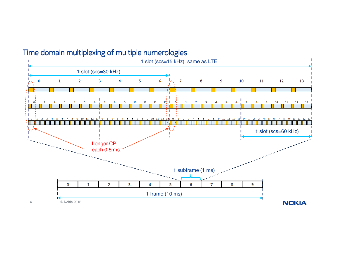
Time domain multiplexing of multiple numerologies
Time domain multiplexing of multiple numerologies
Time domain multiplexing of multiple numerologies
Time domain multiplexing of multiple numerologies
1 slot (scs=15 kHz), same as LTE
1 slot (scs=30 kHz)
Longer CP
each 0.5 ms
1 subframe (1 ms)
1 slot (scs=60 kHz)
4
© Nokia 2016
1 frame (10 ms)
�
Frequency domain multiplexing of multiple numerologies
Frequency domain multiplexing of multiple numerologies
Frequency domain multiplexing of multiple numerologies
Frequency domain multiplexing of multiple numerologies
Point A
Carrier 0
(100 MHz - 273 RB scs=30 kHz)
offsetToCarrier
Carrier 1
(50 MHz - 270 RB scs=15 kHz)
Carrier bandwidth
• Constrained by max 3300 tones (275 RB) but in practice
reduced to max 273 RB
• Carriers associated to different numerology do not
necessarily cover the same frequency span
• Necessity to provide a relative positioning of each carrier
5
© Nokia 2016
Carrier
• Maximum set of consecutive RBs used by a cell for a given numerology
• 1 carrier instance for each numerology actually configured in the cell
Point A
• Absolute reference common to all carriers
• Does not necessarily coincide with CRB #0 of a carrier
• Signaled to UE by absoluteFrequencyPointA (ARFCN)
offsetToCarrier
• Provides position of carrier relative to point A
• Expressed in number of RB using the carrier numerology
�
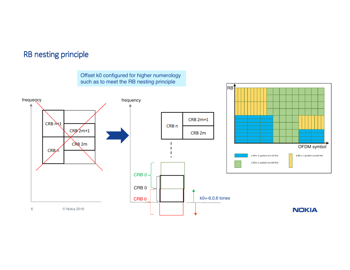
RB nesting principle
RB nesting principle
RB nesting principle
RB nesting principle
Offset k0 configured for higher numerology
such as to meet the RB nesting principle
RB
frequency
frequency
OFDM symbol
CRB 0
CRB 0
CRB 0
k0=-6,0,6 tones
6
© Nokia 2016
�
Bandwidth Part
Bandwidth Part
Bandwidth Part
Bandwidth Part
carrier
௦௭
ܰௐ,
Bandwidth
part
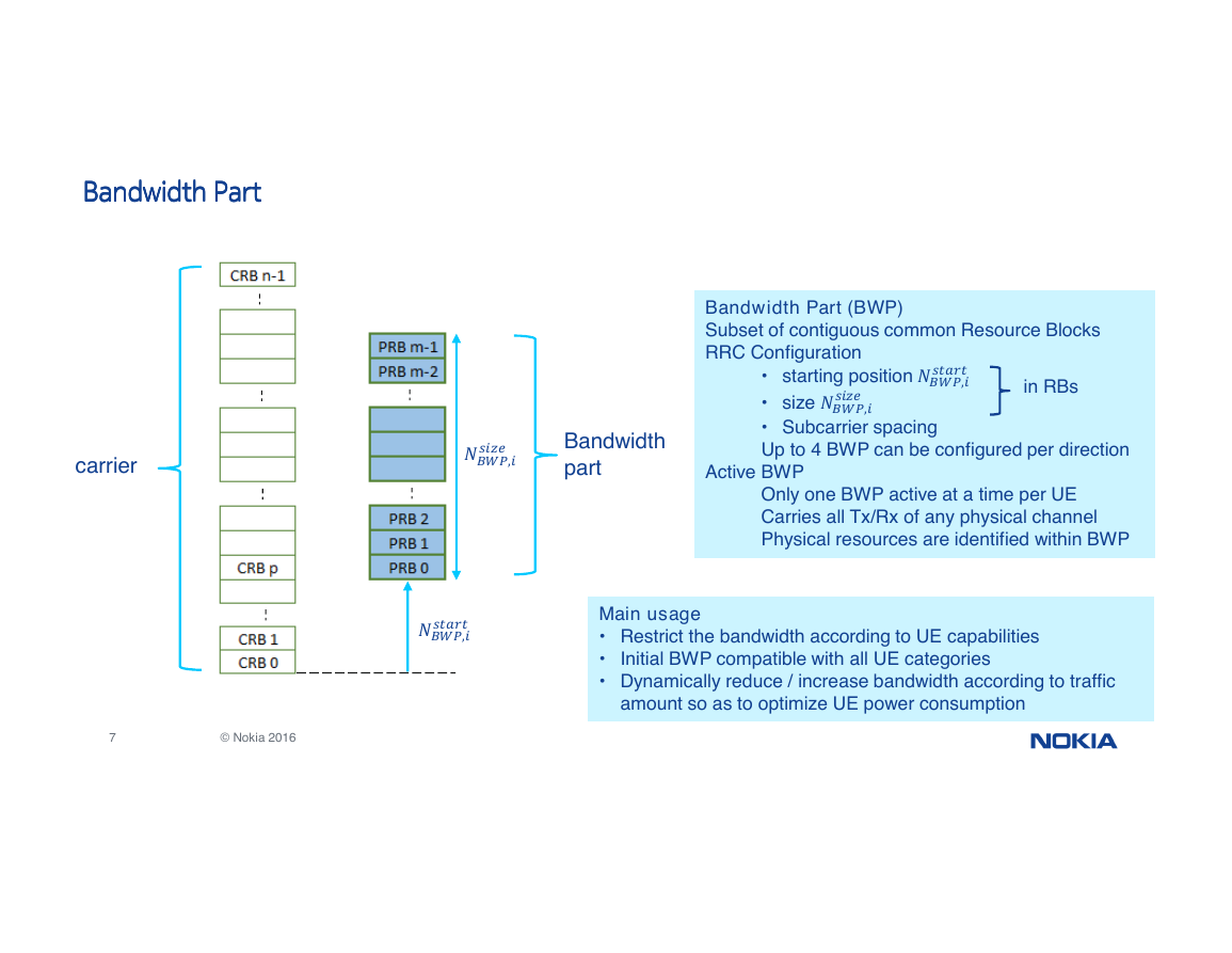
Bandwidth Part (BWP)
Subset of contiguous common Resource Blocks
RRC Configuration
௦௧௧
• starting position ܰௐ,
௦௭
• size ܰௐ,
• Subcarrier spacing
Up to 4 BWP can be configured per direction
in RBs
Active BWP
Only one BWP active at a time per UE
Carries all Tx/Rx of any physical channel
Physical resources are identified within BWP
௦௧௧
ܰௐ,
Main usage
• Restrict the bandwidth according to UE capabilities
•
• Dynamically reduce / increase bandwidth according to traffic
Initial BWP compatible with all UE categories
amount so as to optimize UE power consumption
7
© Nokia 2016
�
Bandwidth Part switching
Bandwidth Part switching
Bandwidth Part switching
Bandwidth Part switching
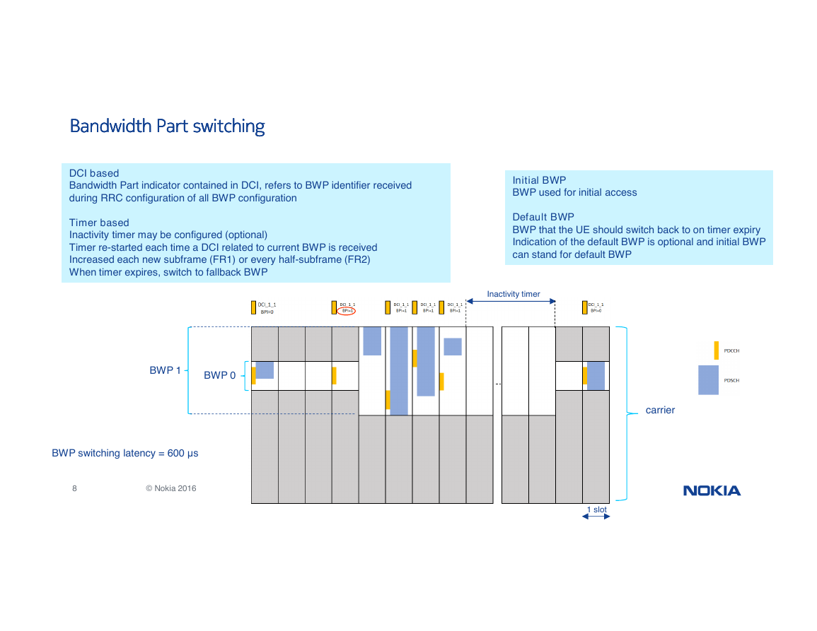
DCI based
Bandwidth Part indicator contained in DCI, refers to BWP identifier received
during RRC configuration of all BWP configuration
Initial BWP
BWP used for initial access
Timer based
Inactivity timer may be configured (optional)
Timer re-started each time a DCI related to current BWP is received
Increased each new subframe (FR1) or every half-subframe (FR2)
When timer expires, switch to fallback BWP
Default BWP
BWP that the UE should switch back to on timer expiry
Indication of the default BWP is optional and initial BWP
can stand for default BWP
Inactivity timer
BWP 1
BWP 0
BWP switching latency = 600 µs
8
© Nokia 2016
carrier
1 slot
�


 2023年江西萍乡中考道德与法治真题及答案.doc
 2012年重庆南川中考生物真题及答案.doc
 2013年江西师范大学地理学综合及文艺理论基础考研真题.doc
 2020年四川甘孜小升初语文真题及答案I卷.doc
 2020年注册岩土工程师专业基础考试真题及答案.doc
 2023-2024学年福建省厦门市九年级上学期数学月考试题及答案.doc
 2021-2022学年辽宁省沈阳市大东区九年级上学期语文期末试题及答案.doc
 2022-2023学年北京东城区初三第一学期物理期末试卷及答案.doc
 2018上半年江西教师资格初中地理学科知识与教学能力真题及答案.doc
 2012年河北国家公务员申论考试真题及答案-省级.doc
 2020-2021学年江苏省扬州市江都区邵樊片九年级上学期数学第一次质量检测试题及答案.doc
 2022下半年黑龙江教师资格证中学综合素质真题及答案.doc