logo资料库

IEC61000-4-21.pdf

第1页 / 共228页
第2页 / 共228页
第3页 / 共228页
第4页 / 共228页
第5页 / 共228页
第6页 / 共228页
第7页 / 共228页
第8页 / 共228页
资料共228页,剩余部分请下载后查看
English
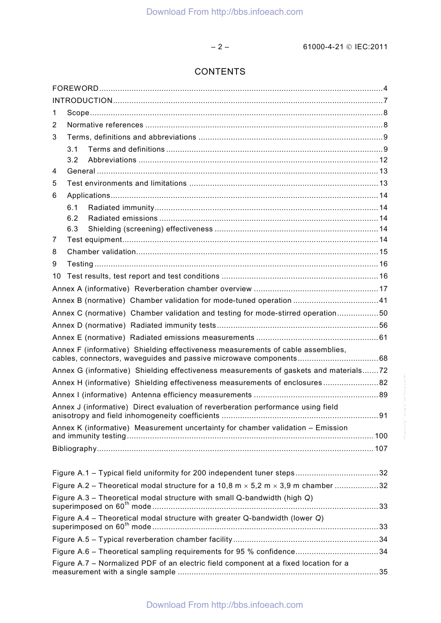
CONTENTS
FOREWORD
INTRODUCTION
1 Scope
2 Normative references
3 Terms, definitions and abbreviations
3.1 Terms and definitions
3.2 Abbreviations
4 General
5 Test environments and limitations
6 Applications
6.1 Radiated immunity
6.2 Radiated emissions
6.3 Shielding (screening) effectiveness
7 Test equipment
8 Chamber validation
9 Testing
10 Test results, test report and test conditions
Annex A (informative) Reverberation chamber overview
Annex B (normative) Chamber validation for mode-tuned operation
Annex C (normative) Chamber validation and testing for mode-stirred operation
Annex D (normative) Radiated immunity tests
Annex E (normative) Radiated emissions measurements
Annex F (informative) Shielding effectiveness measurements of cable assemblies, cables, connectors, waveguides and passive microwave components
Annex G (informative) Shielding effectiveness measurements of gaskets and materials
Annex H (informative) Shielding effectiveness measurements of enclosures
Annex I (informative) Antenna efficiency measurements
Annex J (informative) Direct evaluation of reverberation performance using field anisotropy and field inhomogeneity coefficients
Annex K (informative) M easurement uncertainty for chamber validation – Emission and immunity testing
Bibliography
Figures
Figure A.1 – Typical field uniformity for 200 independent tuner steps
Figure A.2 – Theoretical modal structure for a 10,8 m x 5,2 m x 3,9 m chamber
Figure A.3 – Theoretical modal structure with small Q-bandwidth (high Q) superimposed on 60th mode
Figure A.4 – Theoretical modal structure with greater Q-bandwidth (lower Q) superimposed on 60th mode
Figure A.5 – Typical reverberation chamber facility
Figure A.6 – Theoretical sampling requirements for 95 % confidence
Figure A.7 – Normalized PDF of an electric field component at a fixed location for a measurement with a single sample
Figure A.8 – Normalised PDF of the mean of an electric field component at one fixed location for a measurement with N independent samples
Figure A.9 – Normalised PDF of the maximum of an electric field component at a fixed location for a measurement with N independent samples
Figure A.10 – Chamber working volume
Figure A.11 – Typical probe data
Figure A.12 – Mean-normalized data for x-component of 8 probes
Figure A.13 – Standard deviation of data for E-field components of 8 probes
Figure A.14 – Distribution of absorbers for loading effects test
Figure A.15 – Magnitude of loading from loading effects test
Figure A.16 – Standard deviation data of electric field components for eight probes in the loaded chamber
Figure B.1 – Probe locations for chamber validation
Figure C.1 – Received power (dBm) as a function of tuner rotation (s) at 500 MHz
Figure C.2 – Received power (dBm) as a function of tuner rotation (s) at 1 000 MHz
Figure D.1 – Example of suitable test facility
Figure E.1 – Example of suitable test facility
Figure E.2 – Relating to the calculation of the geometry factor for radiated emissions
Figure F.1 – Typical test set-up
Figure G.1 – Typical test set-up
Figure G.2 – Typical test fixture installation for gasket and/or material testing
Figure G.3 – Test fixture configured for validation
Figure H.1 – Typical test enclosure installation for floor mounted enclosure testing
Figure H.2 – Typical test enclosure installation for bench mounted enclosure testing
Figure J.1 – Theoretical and typical measured distributions for field anisotropy coefficients in a well-stirred chamber
Figure J.2 – Theoretical and typical measured distributions for field anisotropy coefficients in a poorly stirred chamber
Figure J.3 – Typical measured values for field anisotropy coefficients as a function of N in a well-stirred chamber
Figure K.1 – Average emitted power as a function of frequency for a typical unintentional radiator
Figure K.2 – Estimated standard uncertainty
Figure K.3 – Mean normalized width (in dB) of a n% -confidence interval
Figure K.4 – Individual mean-normalized interval boundaries (in linear units) for maximum field strength as a function of the number of independent stirrer positions N
Tables
Table B.1 – Sampling requirements
Table B.2 – Field uniformity tolerance requirements
Table J.1 – Typical values for total field anisotropy coefficients for ‘medium’ and ‘good’ reverberation quality
Français
SOMMAIRE
AVANT-PROPOS
INTRODUCTION
1 Domaine d’application
2 Références normatives
3 Termes, définitions et abréviations
3.1 Termes et définitions
3.2 Abréviations
4 Généralités
5 Environnements d'essai et limitations
6 Applications
6.1 Immunité rayonnée
6.2 Emissions rayonnées
6.3 Mesures de l'efficacité d'écran
7 Matériels d’essai
8 Validation de la chambre
9 Essais
10 Résultats d'essai, rapport d'essai et conditions d'essai
Annexe A (informative) Vue d’ensemble de la chambre réverbérante
Annexe B (normative) Validation de la chambre par brassage de modes pas à pas
Annexe C (normative) Validation de la cha mbre et essais par brassage de modes continu
Annexe D (normative) Essais d’immunité aux émissions rayonnées
Annexe E (normative) Mesures des émissions rayonnées
Annexe F (informative) Mesures d'efficacité d'écran des assemblages de câbles,des câbles, des connecteurs, des guides d'ondes et des composants passifs hyperfréquence
Annexe G (informative) Mesures de l'efficacité de blindage des joints d'étanchéité et des matériaux
Annexe H (informative) Mesures de l'efficacité de blindage des enceintes
Annexe I (informative) Mesures du rendement d'antenne
Annexe J (informative) Evaluation directe des performances de réverbération en utilisant les coefficients d'anisotropie et d'inhomogénéité du champ
Annexe K (informative) Incertitude de mesure pour la validation de la chambre – Essais d’émissions et d’immunité
Bibliographie
Figures
Figure A.1 – Uniformité de champ type pour 200 pas indépendants du brasseur
Figure A.2 – Structure modale théorique pour une chambre de 10,8 m x 5,2 m x 3,9 m
Figure A.3 – Structure modale théorique avec faible largeur de bande du facteur de qualité (Q élevé) superposée sur le 60ème mode
Figure A.4 – Structure modale théorique avec largeur de bande du facteur de qualité plus élevée (Q plus faible) superposée sur le 60ème mode
Figure A.5 – Installation de chambre réverbérante type
Figure A.6 – Exigences d'échantillonnage théorique pour une confiance de 95 %
Figure A.7 – Fonction de densité de probabilité normalisée d'une composante de champ électrique à un emplacement fixe pour une mesure avec un seul échantillon
Figure A.8 – Fonction de densité de probabilité normalisée de la moyenne d'une composante de champ électrique à un emplacement fixe pour une mesure avec N échantillons indépendants
Figure A.9 – Fonction de densité de probabilité normalisée de la valeur maximale d'une composante de champ électrique à un emplacement fixe pour une mesure avec N échantillons indépendants
Figure A.10 – Volume de travail de la chambre
Figure A.11 – Données types de sonde
Figure A.12 – Données normalisées moyennes pour la composante x de 8 sondes
Figure A.13 – Ecart type des données pour les composantes du champ E de 8 sondes
Figure A.14 – Distribution des absorbants pour l'essai relatif aux effets de charge
Figure A.15 – Amplitude de charge pour l'essai relatif aux effets de charge
Figure A.16 – Données d'écart type pour composantes de champ électrique de huit sondes dans la chambre chargée
Figure B.1 – Emplacements de sonde pour la validation de la chambre
Figure C.1 – Puissance reçue (dBm) en fonction de laou des rotation(s) du brasseur à 500 MHz
Figure C.2 – Puissance reçue (dBm) en fonction de la ou des rotationsdu brasseur à 1 000 MHz
Figure D.1 – Exemple d'installation d'essai adaptée
Figure E.1 – Exemple d'installation d'essai adaptée
Figure E.2 – Relation avec le calcul du facteur géométriquepour les émissions rayonnées
Figure F.1 – Montage type d'essai
Figure G.1 – Montage type d'essai
Figure G.2 – Installation d'essai type pour les essaisde joint d'étanchéité et/ou matériau
Figure G.3 – Installation d'essai configurée pour la validation
Figure H.1 – Installation de l'enceinte d'essai type pour les essais d'enceinte de sol
Figure H.2 – Installation de l'enceinte d'essai typepour les essais d'enceintes montées sur banc
Figure J.1 – Distributions théoriques et types mesurées pour les coefficients d'anisotropie de champ dans une chambre bien brassée
Figure J.2 – Distributions théoriques et types mesurées pour les coefficients d'anisotropie de champ dans une chambre mal brassée
Figure J.3 – Valeurs mesurées types pour les coefficients d'anisotropie de champ en fonction de N dans une chambre bien brassée
Figure K.1 – Puissance émise moyenne en fonction de la fréquencepour une antenne non intentionnelle type
Figure K.2 – Incertitude estimée normalisée
Figure K.3 – Largeur moyenne normalisée (en dB) pour un intervalle de confiance à n %
Figure K.4 – Limites d’intervalle moyennes normalisées individuelles (en unités linéaires) pour une intensité de champ maximale en fonction du nombre de positions indépendantes N du brasseur
Tableaux
Tableau B.1 – Exigences d’échantillonnage
Tableau B.2 – Exigences de tolérance pour l’uniformité du champ
Tableau J.1 – Valeurs types pour coefficients d‘anisotropie de champ totale pour une qualité de réverbération «moyenne» et «bonne»
Download From http://bbs.infoeach.com IEC 61000-4-21 Edition 2.0 2011-01 ® INTERNATIONAL STANDARD NORME INTERNATIONALE BASIC EMC PUBLICATION PUBLICATION FONDAMENTALE EN CEM Electromagnetic compatibility (EMC) – Part 4-21: Testing and measurement techniques – Reverberation chamber test methods Compatibilité électromagnétique (CEM) – Partie 4-21: Techniques d'essai et de mesure – Méthodes d'essai en chambre réverbérante 1 1 0 2 : 1 2 - 4 - 0 0 0 1 6 C E I Download From http://bbs.infoeach.com colourinside
Download From http://bbs.infoeach.com THIS PUBLICATION IS COPYRIGHT PROTECTED Copyright © 2011 IEC, Geneva, Switzerland All rights reserved. Unless otherwise specified, no part of this publication may be reproduced or utilized in any form or by any means, electronic or mechanical, including photocopying and microfilm, without permission in writing from either IEC or IEC's member National Committee in the country of the requester. If you have any questions about IEC copyright or have an enquiry about obtaining additional rights to this publication, please contact the address below or your local IEC member National Committee for further information. Droits de reproduction réservés. Sauf indication contraire, aucune partie de cette publication ne peut être reproduite ni utilisée sous quelque forme que ce soit et par aucun procédé, électronique ou mécanique, y compris la photocopie et les microfilms, sans l'accord écrit de la CEI ou du Comité national de la CEI du pays du demandeur. Si vous avez des questions sur le copyright de la CEI ou si vous désirez obtenir des droits supplémentaires sur cette publication, utilisez les coordonnées ci-après ou contactez le Comité national de la CEI de votre pays de résidence. IEC Central Office 3, rue de Varembé CH-1211 Geneva 20 Switzerland Email: inmail@iec.ch Web: www.iec.ch About the IEC The International Electrotechnical Commission (IEC) is the leading global organization that prepares and publishes International Standards for all electrical, electronic and related technologies. About IEC publications The technical content of IEC publications is kept under constant review by the IEC. Please make sure that you have the latest edition, a corrigenda or an amendment might have been published.  Catalogue of IEC publications: www.iec.ch/searchpub The IEC on-line Catalogue enables you to search by a variety of criteria (reference number, text, technical committee,…). It also gives information on projects, withdrawn and replaced publications.  IEC Just Published: www.iec.ch/online_news/justpub Stay up to date on all new IEC publications. Just Published details twice a month all new publications released. Available on-line and also by email.  Electropedia: www.electropedia.org The world's leading online dictionary of electronic and electrical terms containing more than 20 000 terms and definitions in English and French, with equivalent terms in additional languages. Also known as the International Electrotechnical Vocabulary online.  Customer Service Centre: www.iec.ch/webstore/custserv If you wish to give us your feedback on this publication or need further assistance, please visit the Customer Service Centre FAQ or contact us: Email: csc@iec.ch Tel.: +41 22 919 02 11 Fax: +41 22 919 03 00 A propos de la CEI La Commission Electrotechnique Internationale (CEI) est la première organisation mondiale qui élabore et publie des normes internationales pour tout ce qui a trait à l'électricité, à l'électronique et aux technologies apparentées. A propos des publications CEI Le contenu technique des publications de la CEI est constamment revu. Veuillez vous assurer que vous possédez l’édition la plus récente, un corrigendum ou amendement peut avoir été publié.  Catalogue des publications de la CEI: www.iec.ch/searchpub/cur_fut-f.htm Le Catalogue en-ligne de la CEI vous permet d’effectuer des recherches en utilisant différents critères (numéro de référence, texte, comité d’études,…). Il donne aussi des informations sur les projets et les publications retirées ou remplacées.  Just Published CEI: www.iec.ch/online_news/justpub Restez informé sur les nouvelles publications de la CEI. Just Published détaille deux fois par mois les nouvelles publications parues. Disponible en-ligne et aussi par email.  Electropedia: www.electropedia.org Le premier dictionnaire en ligne au monde de termes électroniques et électriques. Il contient plus de 20 000 termes et définitions en anglais et en français, ainsi que les termes équivalents dans les langues additionnelles. Egalement appelé Vocabulaire Electrotechnique International en ligne.  Service Clients: www.iec.ch/webstore/custserv/custserv_entry-f.htm Si vous désirez nous donner des commentaires sur cette publication ou si vous avez des questions, visitez le FAQ du Service clients ou contactez-nous: Email: csc@iec.ch Tél.: +41 22 919 02 11 Fax: +41 22 919 03 00 Download From http://bbs.infoeach.com
Download From http://bbs.infoeach.com IEC 61000-4-21 Edition 2.0 2011-01 ® INTERNATIONAL STANDARD NORME INTERNATIONALE BASIC EMC PUBLICATION PUBLICATION FONDAMENTALE EN CEM Electromagnetic compatibility (EMC) – Part 4-21: Testing and measurement techniques – Reverberation chamber test methods Compatibilité électromagnétique (CEM) – Partie 4-21: Techniques d'essai et de mesure – Méthodes d'essai en chambre réverbérante INTERNATIONAL ELECTROTECHNICAL COMMISSION COMMISSION ELECTROTECHNIQUE INTERNATIONALE ICS 33.100.10; 33.100.20 PRICE CODE CODE PRIX XE ISBN 978-2-88912-324-7 ® Registered trademark of the International Electrotechnical Commission Marque déposée de la Commission Electrotechnique Internationale Download From http://bbs.infoeach.com colourinside--`,,,,`,`,`,,````,,`,,,`,```,,-`-`,,`,,`,`,,`---
Download From http://bbs.infoeach.com – 2 – 61000-4-21  IEC:2011 CONTENTS FOREWORD ........................................................................................................................... 4 INTRODUCTION ..................................................................................................................... 7 1 Scope ............................................................................................................................... 8 2 Normative references ....................................................................................................... 8 3 Terms, definitions and abbreviations ................................................................................ 9 3.1 Terms and definitions .............................................................................................. 9 3.2 Abbreviations ........................................................................................................ 12 4 General .......................................................................................................................... 13 5 Test environments and limitations .................................................................................. 13 6 Applications .................................................................................................................... 14 6.1 Radiated immunity ................................................................................................. 14 6.2 Radiated emissions ............................................................................................... 14 6.3 Shielding (screening) effectiveness ....................................................................... 14 7 Test equipment ............................................................................................................... 14 8 Chamber validation......................................................................................................... 15 9 Testing ........................................................................................................................... 16 10 Test results, test report and test conditions .................................................................... 16 Annex A (informative) Reverberation chamber overview ...................................................... 17 Annex B (normative) Chamber validation for mode-tuned operation ..................................... 41 Annex C (normative) Chamber validation and testing for mode-stirred operation .................. 50 Annex D (normative) Radiated immunity tests ...................................................................... 56 Annex E (normative) Radiated emissions measurements ..................................................... 61 Annex F (informative) Shielding effectiveness measurements of cable assemblies, cables, connectors, waveguides and passive microwave components ................................... 68 Annex G (informative) Shielding effectiveness measurements of gaskets and materials ....... 72 Annex H (informative) Shielding effectiveness measurements of enclosures ........................ 82 Annex I (informative) Antenna efficiency measurements ...................................................... 89 Annex J (informative) Direct evaluation of reverberation performance using field anisotropy and field inhomogeneity coefficients .................................................................... 91 Annex K (informative) Measurement uncertainty for chamber validation – Emission and immunity testing ........................................................................................................... 100 Bibliography ........................................................................................................................ 107 Figure A.1 – Typical field uniformity for 200 independent tuner steps .................................... 32 Figure A.2 – Theoretical modal structure for a 10,8 m × 5,2 m × 3,9 m chamber ................... 32 Figure A.3 – Theoretical modal structure with small Q-bandwidth (high Q) superimposed on 60th mode .................................................................................................. 33 Figure A.4 – Theoretical modal structure with greater Q-bandwidth (lower Q) superimposed on 60th mode .................................................................................................. 33 Figure A.5 – Typical reverberation chamber facility ............................................................... 34 Figure A.6 – Theoretical sampling requirements for 95 % confidence .................................... 34 Figure A.7 – Normalized PDF of an electric field component at a fixed location for a measurement with a single sample ....................................................................................... 35 Download From http://bbs.infoeach.com --`,,,,`,`,`,,````,,`,,,`,```,,-`-`,,`,,`,`,,`---
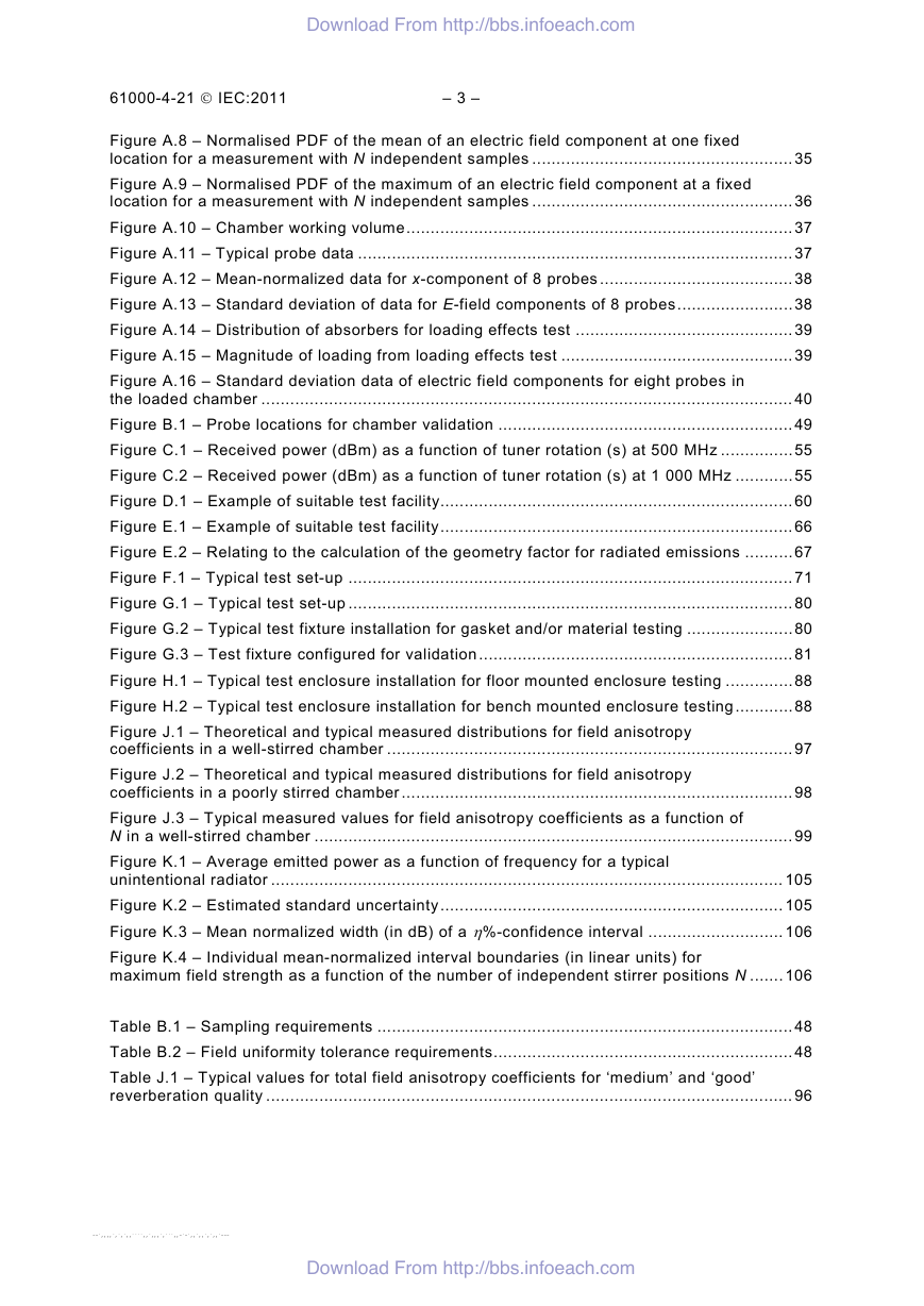
Download From http://bbs.infoeach.com 61000-4-21  IEC:2011 – 3 – Figure A.8 – Normalised PDF of the mean of an electric field component at one fixed location for a measurement with N independent samples ...................................................... 35 Figure A.9 – Normalised PDF of the maximum of an electric field component at a fixed location for a measurement with N independent samples ...................................................... 36 Figure A.10 – Chamber working volume ................................................................................ 37 Figure A.11 – Typical probe data .......................................................................................... 37 Figure A.12 – Mean-normalized data for x-component of 8 probes ........................................ 38 Figure A.13 – Standard deviation of data for E-field components of 8 probes ........................ 38 Figure A.14 – Distribution of absorbers for loading effects test ............................................. 39 Figure A.15 – Magnitude of loading from loading effects test ................................................ 39 Figure A.16 – Standard deviation data of electric field components for eight probes in the loaded chamber .............................................................................................................. 40 Figure B.1 – Probe locations for chamber validation ............................................................. 49 Figure C.1 – Received power (dBm) as a function of tuner rotation (s) at 500 MHz ............... 55 Figure C.2 – Received power (dBm) as a function of tuner rotation (s) at 1 000 MHz ............ 55 Figure D.1 – Example of suitable test facility......................................................................... 60 Figure E.1 – Example of suitable test facility ......................................................................... 66 Figure E.2 – Relating to the calculation of the geometry factor for radiated emissions .......... 67 Figure F.1 – Typical test set-up ............................................................................................ 71 Figure G.1 – Typical test set-up ............................................................................................ 80 Figure G.2 – Typical test fixture installation for gasket and/or material testing ...................... 80 Figure G.3 – Test fixture configured for validation ................................................................. 81 Figure H.1 – Typical test enclosure installation for floor mounted enclosure testing .............. 88 Figure H.2 – Typical test enclosure installation for bench mounted enclosure testing ............ 88 Figure J.1 – Theoretical and typical measured distributions for field anisotropy coefficients in a well-stirred chamber .................................................................................... 97 Figure J.2 – Theoretical and typical measured distributions for field anisotropy coefficients in a poorly stirred chamber ................................................................................. 98 Figure J.3 – Typical measured values for field anisotropy coefficients as a function of N in a well-stirred chamber ................................................................................................... 99 Figure K.1 – Average emitted power as a function of frequency for a typical unintentional radiator .......................................................................................................... 105 Figure K.2 – Estimated standard uncertainty ....................................................................... 105 Figure K.3 – Mean normalized width (in dB) of a η%-confidence interval ............................ 106 Figure K.4 – Individual mean-normalized interval boundaries (in linear units) for maximum field strength as a function of the number of independent stirrer positions N ....... 106 Table B.1 – Sampling requirements ...................................................................................... 48 Table B.2 – Field uniformity tolerance requirements .............................................................. 48 Table J.1 – Typical values for total field anisotropy coefficients for ‘medium’ and ‘good’ reverberation quality ............................................................................................................. 96 Download From http://bbs.infoeach.com --`,,,,`,`,`,,````,,`,,,`,```,,-`-`,,`,,`,`,,`---
Download From http://bbs.infoeach.com – 4 – 61000-4-21  IEC:2011 INTERNATIONAL ELECTROTECHNICAL COMMISSION ____________ ELECTROMAGNETIC COMPATIBILITY (EMC) – Part 4-21: Testing and measurement techniques – Reverberation chamber test methods FOREWORD 1) The International Electrotechnical Commission (IEC) is a worldwide organization for standardization comprising all national electrotechnical committees (IEC National Committees). The object of IEC is to promote international co-operation on all questions concerning standardization in the electrical and electronic fields. To this end and in addition to other activities, IEC publishes International Standards, Technical Specifications, Technical Reports, Publicly Available Specifications (PAS) and Guides (hereafter referred to as “IEC Publication(s)”). Their preparation is entrusted to technical committees; any IEC National Committee interested in the subject dealt with may participate in this preparatory work. International, governmental and non- governmental organizations liaising with the IEC also participate in this preparation. IEC collaborates closely with the International Organization for Standardization (ISO) in accordance with conditions determined by agreement between the two organizations. 2) The formal decisions or agreements of IEC on technical matters express, as nearly as possible, an international consensus of opinion on the relevant subjects since each technical committee has representation from all interested IEC National Committees. 3) IEC Publications have the form of recommendations for international use and are accepted by IEC National Committees in that sense. While all reasonable efforts are made to ensure that the technical content of IEC Publications is accurate, IEC cannot be held responsible for the way in which they are used or for any misinterpretation by any end user. 4) In order to promote international uniformity, IEC National Committees undertake to apply IEC Publications transparently to the maximum extent possible in their national and regional publications. Any divergence between any IEC Publication and the corresponding national or regional publication shall be clearly indicated in the latter. 5) IEC itself does not provide any attestation of conformity. Independent certification bodies provide conformity assessment services and, in some areas, access to IEC marks of conformity. IEC is not responsible for any services carried out by independent certification bodies. 6) All users should ensure that they have the latest edition of this publication. 7) No liability shall attach to IEC or its directors, employees, servants or agents including individual experts and members of its technical committees and IEC National Committees for any personal injury, property damage or other damage of any nature whatsoever, whether direct or indirect, or for costs (including legal fees) and expenses arising out of the publication, use of, or reliance upon, this IEC Publication or any other IEC Publications. 8) Attention is drawn to the Normative references cited in this publication. Use of the referenced publications is indispensable for the correct application of this publication. 9) Attention is drawn to the possibility that some of the elements of this IEC Publication may be the subject of patent rights. IEC shall not be held responsible for identifying any or all such patent rights. International Standard IEC 61000-4-21 has been prepared by subcommittee 77B: High frequency phenomena, of IEC technical committee 77: Electromagnetic compatibility, in co- operation with CISPR subcommittee A: Radio-interference measurements and statistical methods. It forms Part 4-21 of IEC 61000. It has the status of a basic EMC publication in accordance with IEC Guide 107. This second edition cancels and replaces the first edition published in 2003. This edition constitutes a technical revision. This edition includes the following significant technical changes with respect to the first edition. • In Clause 8, the use and specifications of E-field probes for application to reverberation chambers has been added. Additional Notes refer to general aspects and procedures of Download From http://bbs.infoeach.com
Download From http://bbs.infoeach.com 61000-4-21  IEC:2011 – 5 – probe calibrations. The specified range for linearity of the probe response is larger and covers an asymmetric interval compared to that for use in anechoic chambers (see Annex I of IEC 61000-4-3), because – the fluctuations of power and fields in reverberation chambers exhibit a larger dynamic range, and the chamber validation procedure is based on using maximum field values, as opposed to the field itself or its average value, – • • respectively. In Annex A, additional guidance and clarifications on the use of reverberation chambers at relatively low frequencies of operation (i.e., close to the lowest usable frequency of a given chamber) are given, and its implications on the estimation of field uncertainty are outlined. Guidelines on cable-layout have been added. A rationale has been added that explains the relaxation of the field uniformity requirement below 400 MHz, being a compromise between scientific-technical and economical reasons when using chambers around 100 MHz. A first-order correction for the threshold value of the correlation coefficient at relatively low numbers of tuner positions has been added. Issues regarding the use of non-equidistant tuner positions at low frequencies are discussed in an additional Note. In Annex B, symmetric location of the field probes when the chamber exhibits cylindrical symmetry has been disallowed, as such placement could otherwise yield a false indication of field uniformity and chamber performance at different locations. The difference between start frequency for chamber validation and lowest test frequency has been clarified. The tuner sequencing for chamber validation and testing is now specified to be equal in both cases. In sample requirements for chamber validation, emphasis is now on the required minimum number of independent tuner steps to be used, whereas the minimum recommended number of samples per frequency interval has been replaced with he number of independent samples that the tuner can provide per frequency, for use in case when the chamber validation fails for the required minimum number. • Annex C now contains more quantitative guidance on the setting of the maximum permissible stirring speeds that warrant quasi-static conditions of operation for chamber validation and testing. Consideration is given to all characteristic time scales of all components or subsystems of a measurement or test. Specific issues relating to chamber validation, immunity testing and bandwidth are addressed. Particular requirements for field probes when used with mode stirred operation are listed. In Annex D, a requirement for the EUT and equipment not to occupy more than 8 % of the total chamber volume in immunity testing has been added. The maximum number of frequency points and the formula to calculate these points have been generalized. A mandatory specification for including the measurement equipment, test plan and cable layout in the test report has been added to resolve any dispute in case of discrepancies, particularly for low-frequency immunity testing. • • Annex E has been extended with further guidance on the value of EUT directivity to be used in the estimation of radiated power and field. Extended estimates have been added for the maximum directivity of electrically large, anisotropically radiating EUTs and for radiated emissions in the presence of a ground plane. A mandatory specification for including the measurement equipment, test plan and cable layout in the test report has been added to resolve any dispute in case of discrepancies, particularly for low-frequency emissions testing. In Annex I, some clarifications on antenna efficiency measurements have been added. • • A new Annex K has been added that covers measurement uncertainty in reverberation chambers. The intrinsic field uncertainty for chamber validation, immunity and emissions measurements is quantified. Other contributors to measurement uncertainty are listed. Download From http://bbs.infoeach.com
Download From http://bbs.infoeach.com – 6 – 61000-4-21  IEC:2011 The text of this standard is based on the following documents: CDV 77B/619/CDV Report on voting 77B/640/RVC Full information on the voting for the approval of this standard can be found in the report on voting indicated in the above table. This publication has been drafted in accordance with the ISO/IEC Directives, Part 2. The committee has decided that the contents of this publication will remain unchanged until the stability date indicated on the IEC web site under "http://webstore.iec.ch" in the data related to the specific publication. At this date, the publication will be reconfirmed, • • withdrawn, • • amended. replaced by a revised edition, or it contains colours which are considered IMPORTANT – The 'colour inside' logo on the cover page of this publication indicates that the correct understanding of its contents. Users should therefore print this document using a colour printer. to be useful for Download From http://bbs.infoeach.com
分享到:
收藏