Micron Confidential and Proprietary
8GB, 16GB, 32GB, 64GB, 128GB: e.MMC (Automotive)
Features
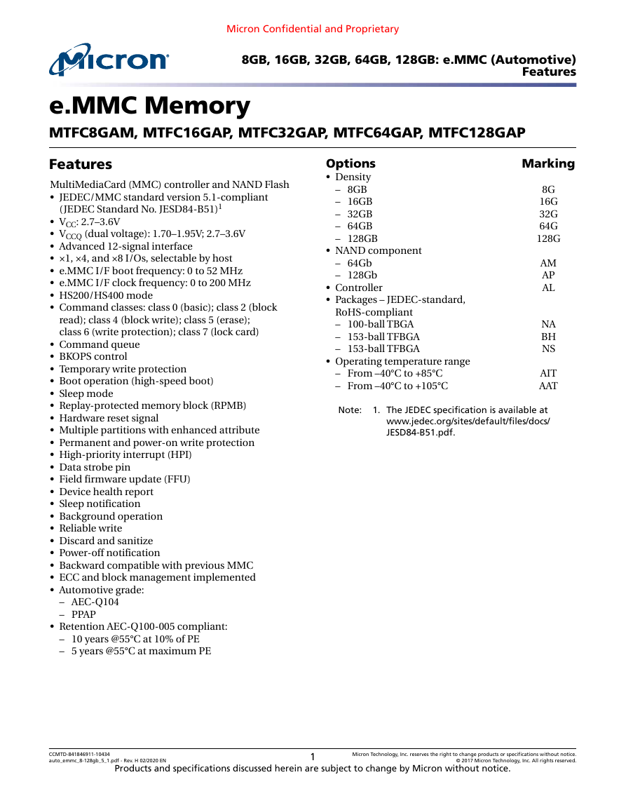
e.MMC Memory
MTFC8GAM, MTFC16GAP, MTFC32GAP, MTFC64GAP, MTFC128GAP
Options
• Density
– 8GB
– 16GB
– 32GB
– 64GB
– 128GB
• NAND component
– 64Gb
– 128Gb
• Controller
• Packages – JEDEC-standard,
RoHS-compliant
– 100-ball TBGA
– 153-ball TFBGA
– 153-ball TFBGA
• Operating temperature range
– From –40°C to +85°C
– From –40°C to +105°C
Marking
8G
16G
32G
64G
128G
AM
AP
AL
NA
BH
NS
AIT
AAT
Note:
1. The JEDEC specification is available at
www.jedec.org/sites/default/files/docs/
JESD84-B51.pdf.
Features
MultiMediaCard (MMC) controller and NAND Flash
• JEDEC/MMC standard version 5.1-compliant
(JEDEC Standard No. JESD84-B51)1
• VCC: 2.7–3.6V
• VCCQ (dual voltage): 1.70–1.95V; 2.7–3.6V
• Advanced 12-signal interface
• ×1, ×4, and ×8 I/Os, selectable by host
• e.MMC I/F boot frequency: 0 to 52 MHz
• e.MMC I/F clock frequency: 0 to 200 MHz
• HS200/HS400 mode
• Command classes: class 0 (basic); class 2 (block
read); class 4 (block write); class 5 (erase);
class 6 (write protection); class 7 (lock card)
• Command queue
• BKOPS control
• Temporary write protection
• Boot operation (high-speed boot)
• Sleep mode
• Replay-protected memory block (RPMB)
• Hardware reset signal
• Multiple partitions with enhanced attribute
• Permanent and power-on write protection
• High-priority interrupt (HPI)
• Data strobe pin
• Field firmware update (FFU)
• Device health report
• Sleep notification
• Background operation
• Reliable write
• Discard and sanitize
• Power-off notification
• Backward compatible with previous MMC
• ECC and block management implemented
• Automotive grade:
– AEC-Q104
– PPAP
• Retention AEC-Q100-005 compliant:
– 10 years @55°C at 10% of PE
– 5 years @55°C at maximum PE
CCMTD-841846911-10434
auto_emmc_8-128gb_5_1.pdf - Rev. H 02/2020 EN
Products and specifications discussed herein are subject to change by Micron without notice.
1
Micron Technology, Inc. reserves the right to change products or specifications without notice.
© 2017 Micron Technology, Inc. All rights reserved.
�
Micron Confidential and Proprietary
8GB, 16GB, 32GB, 64GB, 128GB: e.MMC (Automotive)
Features
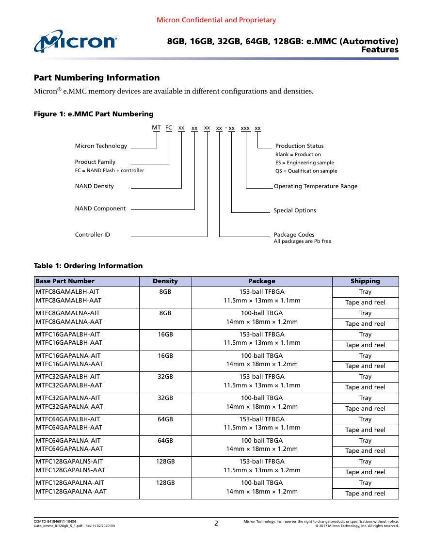
Part Numbering Information
Micron® e.MMC memory devices are available in different configurations and densities.
Figure 1: e.MMC Part Numbering
MT FC
xx
xx
xx
xx
-
xx
xxx
xx
Micron Technology
Product Family
FC = NAND Flash + controller
NAND Density
NAND Component
Controller ID
Table 1: Ordering Information
Base Part Number
MTFC8GAMALBH-AIT
MTFC8GAMALBH-AAT
MTFC8GAMALNA-AIT
MTFC8GAMALNA-AAT
MTFC16GAPALBH-AIT
MTFC16GAPALBH-AAT
MTFC16GAPALNA-AIT
MTFC16GAPALNA-AAT
MTFC32GAPALBH-AIT
MTFC32GAPALBH-AAT
MTFC32GAPALNA-AIT
MTFC32GAPALNA-AAT
MTFC64GAPALBH-AIT
MTFC64GAPALBH-AAT
MTFC64GAPALNA-AIT
MTFC64GAPALNA-AAT
MTFC128GAPALNS-AIT
MTFC128GAPALNS-AAT
MTFC128GAPALNA-AIT
MTFC128GAPALNA-AAT
Density
8GB
8GB
16GB
16GB
32GB
32GB
64GB
64GB
128GB
128GB
Production Status
Blank = Production
ES = Engineering sample
QS = Qualification sample
Operating Temperature Range
Special Options
Package Codes
All packages are Pb free
Package
153-ball TFBGA
11.5mm × 13mm × 1.1mm
100-ball TBGA
14mm × 18mm × 1.2mm
153-ball TFBGA
11.5mm × 13mm × 1.1mm
100-ball TBGA
14mm × 18mm × 1.2mm
153-ball TFBGA
11.5mm × 13mm × 1.1mm
100-ball TBGA
14mm × 18mm × 1.2mm
153-ball TFBGA
11.5mm × 13mm × 1.1mm
100-ball TBGA
14mm × 18mm × 1.2mm
153-ball TFBGA
11.5mm × 13mm × 1.2mm
100-ball TBGA
14mm × 18mm × 1.2mm
Shipping
Tray
Tape and reel
Tray
Tape and reel
Tray
Tape and reel
Tray
Tape and reel
Tray
Tape and reel
Tray
Tape and reel
Tray
Tape and reel
Tray
Tape and reel
Tray
Tape and reel
Tray
Tape and reel
CCMTD-841846911-10434
auto_emmc_8-128gb_5_1.pdf - Rev. H 02/2020 EN
2
Micron Technology, Inc. reserves the right to change products or specifications without notice.
© 2017 Micron Technology, Inc. All rights reserved.
�
Micron Confidential and Proprietary
8GB, 16GB, 32GB, 64GB, 128GB: e.MMC (Automotive)
Features
Device Marking
Due to the size of the package, the Micron-standard part number is not printed on the top of the device. Instead,
an abbreviated device mark consisting of a 5-digit alphanumeric code is used. The abbreviated device marks are
cross-referenced to the Micron part numbers at the FBGA Part Marking Decoder site: www.micron.com/decoder.
e.MMC Performance
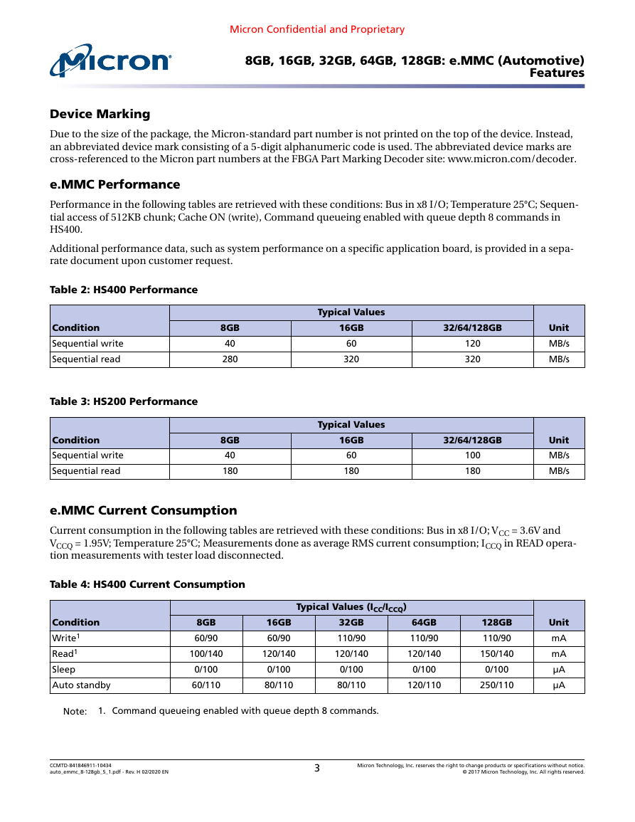
Performance in the following tables are retrieved with these conditions: Bus in x8 I/O; Temperature 25°C; Sequen-
tial access of 512KB chunk; Cache ON (write), Command queueing enabled with queue depth 8 commands in
HS400.
Additional performance data, such as system performance on a specific application board, is provided in a sepa-
rate document upon customer request.
Table 2: HS400 Performance
Condition
Sequential write
Sequential read
Table 3: HS200 Performance
Condition
Sequential write
Sequential read
8GB
40
280
8GB
40
180
Typical Values
16GB
60
320
Typical Values
16GB
60
180
32/64/128GB
120
320
32/64/128GB
100
180
Unit
MB/s
MB/s
Unit
MB/s
MB/s
e.MMC Current Consumption
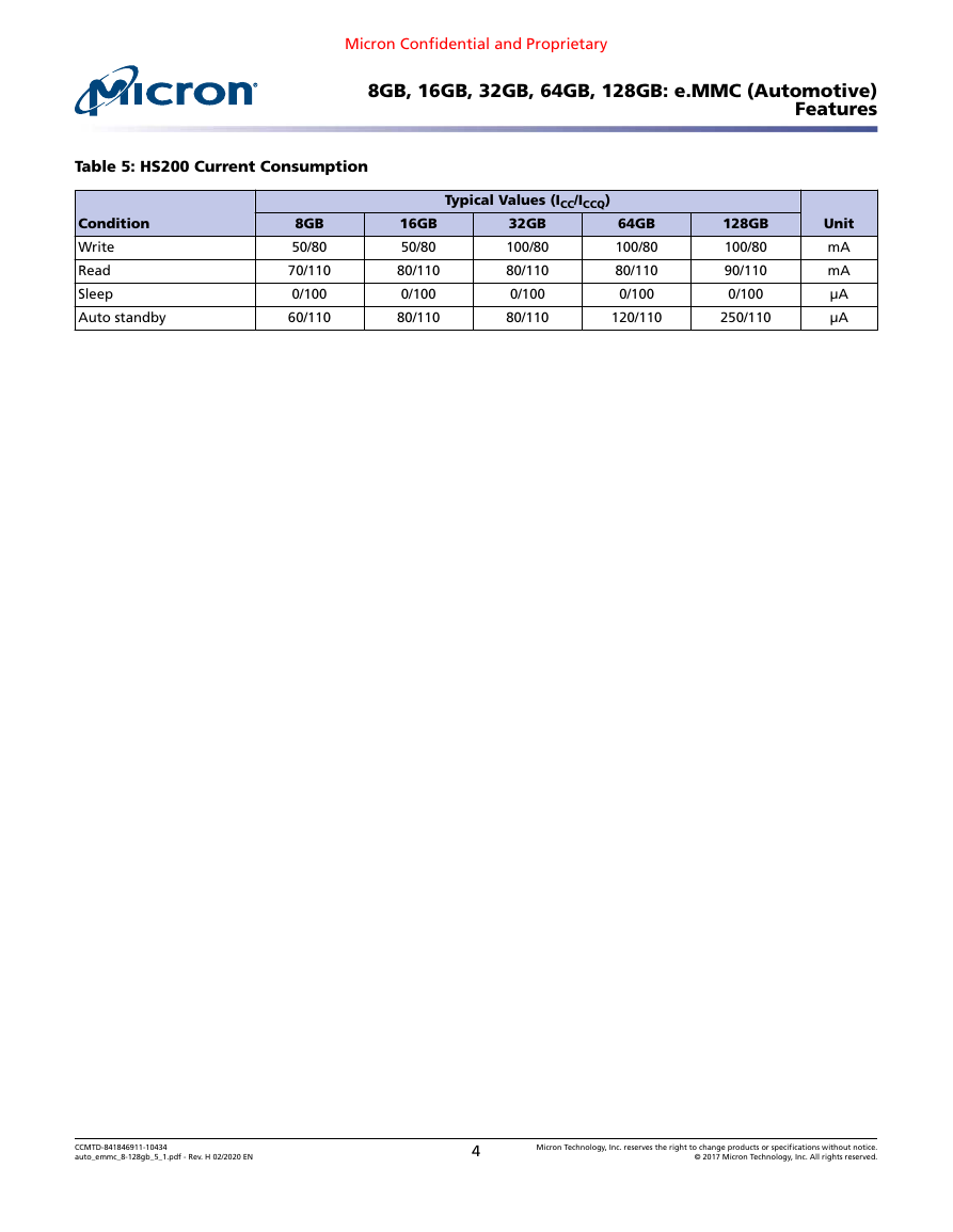
Current consumption in the following tables are retrieved with these conditions: Bus in x8 I/O; VCC = 3.6V and
VCCQ = 1.95V; Temperature 25°C; Measurements done as average RMS current consumption; ICCQ in READ opera-
tion measurements with tester load disconnected.
Table 4: HS400 Current Consumption
Condition
Write1
Read1
Sleep
Auto standby
Typical Values (ICC/ICCQ)
8GB
60/90
100/140
0/100
60/110
16GB
60/90
120/140
0/100
80/110
32GB
110/90
120/140
0/100
80/110
64GB
110/90
120/140
0/100
120/110
128GB
110/90
150/140
0/100
250/110
Unit
mA
mA
µA
µA
Note:
1. Command queueing enabled with queue depth 8 commands.
CCMTD-841846911-10434
auto_emmc_8-128gb_5_1.pdf - Rev. H 02/2020 EN
3
Micron Technology, Inc. reserves the right to change products or specifications without notice.
© 2017 Micron Technology, Inc. All rights reserved.
�
Micron Confidential and Proprietary
8GB, 16GB, 32GB, 64GB, 128GB: e.MMC (Automotive)
Features
Table 5: HS200 Current Consumption
Condition
Write
Read
Sleep
Auto standby
Typical Values (ICC/ICCQ)
8GB
50/80
70/110
0/100
60/110
16GB
50/80
80/110
0/100
80/110
32GB
100/80
80/110
0/100
80/110
64GB
100/80
80/110
0/100
120/110
128GB
100/80
90/110
0/100
250/110
Unit
mA
mA
µA
µA
CCMTD-841846911-10434
auto_emmc_8-128gb_5_1.pdf - Rev. H 02/2020 EN
4
Micron Technology, Inc. reserves the right to change products or specifications without notice.
© 2017 Micron Technology, Inc. All rights reserved.
�
Micron Confidential and Proprietary
8GB, 16GB, 32GB, 64GB, 128GB: e.MMC (Automotive)
Important Notes and Warnings
Important Notes and Warnings
Micron Technology, Inc. ("Micron") reserves the right to make changes to information published in this document,
including without limitation specifications and product descriptions. This document supersedes and replaces all
information supplied prior to the publication hereof. You may not rely on any information set forth in this docu-
ment if you obtain the product described herein from any unauthorized distributor or other source not authorized
by Micron.
Automotive Applications. Products are not designed or intended for use in automotive applications unless specifi-
cally designated by Micron as automotive-grade by their respective data sheets. Distributor and customer/distrib-
utor shall assume the sole risk and liability for and shall indemnify and hold Micron harmless against all claims,
costs, damages, and expenses and reasonable attorneys' fees arising out of, directly or indirectly, any claim of
product liability, personal injury, death, or property damage resulting directly or indirectly from any use of non-
automotive-grade products in automotive applications. Customer/distributor shall ensure that the terms and con-
ditions of sale between customer/distributor and any customer of distributor/customer (1) state that Micron
products are not designed or intended for use in automotive applications unless specifically designated by Micron
as automotive-grade by their respective data sheets and (2) require such customer of distributor/customer to in-
demnify and hold Micron harmless against all claims, costs, damages, and expenses and reasonable attorneys'
fees arising out of, directly or indirectly, any claim of product liability, personal injury, death, or property damage
resulting from any use of non-automotive-grade products in automotive applications.
Critical Applications. Products are not authorized for use in applications in which failure of the Micron compo-
nent could result, directly or indirectly in death, personal injury, or severe property or environmental damage
("Critical Applications"). Customer must protect against death, personal injury, and severe property and environ-
mental damage by incorporating safety design measures into customer's applications to ensure that failure of the
Micron component will not result in such harms. Should customer or distributor purchase, use, or sell any Micron
component for any critical application, customer and distributor shall indemnify and hold harmless Micron and
its subsidiaries, subcontractors, and affiliates and the directors, officers, and employees of each against all claims,
costs, damages, and expenses and reasonable attorneys' fees arising out of, directly or indirectly, any claim of
product liability, personal injury, or death arising in any way out of such critical application, whether or not Mi-
cron or its subsidiaries, subcontractors, or affiliates were negligent in the design, manufacture, or warning of the
Micron product.
Customer Responsibility. Customers are responsible for the design, manufacture, and operation of their systems,
applications, and products using Micron products. ALL SEMICONDUCTOR PRODUCTS HAVE INHERENT FAIL-
URE RATES AND LIMITED USEFUL LIVES. IT IS THE CUSTOMER'S SOLE RESPONSIBILITY TO DETERMINE
WHETHER THE MICRON PRODUCT IS SUITABLE AND FIT FOR THE CUSTOMER'S SYSTEM, APPLICATION, OR
PRODUCT. Customers must ensure that adequate design, manufacturing, and operating safeguards are included
in customer's applications and products to eliminate the risk that personal injury, death, or severe property or en-
vironmental damages will result from failure of any semiconductor component.
Limited Warranty. In no event shall Micron be liable for any indirect, incidental, punitive, special or consequential
damages (including without limitation lost profits, lost savings, business interruption, costs related to the removal
or replacement of any products or rework charges) whether or not such damages are based on tort, warranty,
breach of contract or other legal theory, unless explicitly stated in a written agreement executed by Micron's duly
authorized representative.
CCMTD-841846911-10434
auto_emmc_8-128gb_5_1.pdf - Rev. H 02/2020 EN
5
Micron Technology, Inc. reserves the right to change products or specifications without notice.
© 2017 Micron Technology, Inc. All rights reserved.
�
Micron Confidential and Proprietary
8GB, 16GB, 32GB, 64GB, 128GB: e.MMC (Automotive)
General Description
General Description
Micron e.MMC is a communication and mass data storage device that includes a Multi-
MediaCard (MMC) interface, a NAND Flash component, and a controller on an ad-
vanced 12-signal bus, which is compliant with the MMC system specification. Its cost
per bit, small package sizes, and high reliability make it an ideal choice for automotive
applications, including information and entertainment, navigation tools, advanced
driving assistance systems, and a variety of other industrial and portable products.
The nonvolatile e.MMC draws no power to maintain stored data, delivers high perform-
ance across a wide range of operating temperatures, and resists shock and vibration dis-
ruption.
CCMTD-841846911-10434
auto_emmc_8-128gb_5_1.pdf - Rev. H 02/2020 EN
6
Micron Technology, Inc. reserves the right to change products or specifications without notice.
© 2017 Micron Technology, Inc. All rights reserved.
�
Micron Confidential and Proprietary
8GB, 16GB, 32GB, 64GB, 128GB: e.MMC (Automotive)
Signal Descriptions
Signal Descriptions
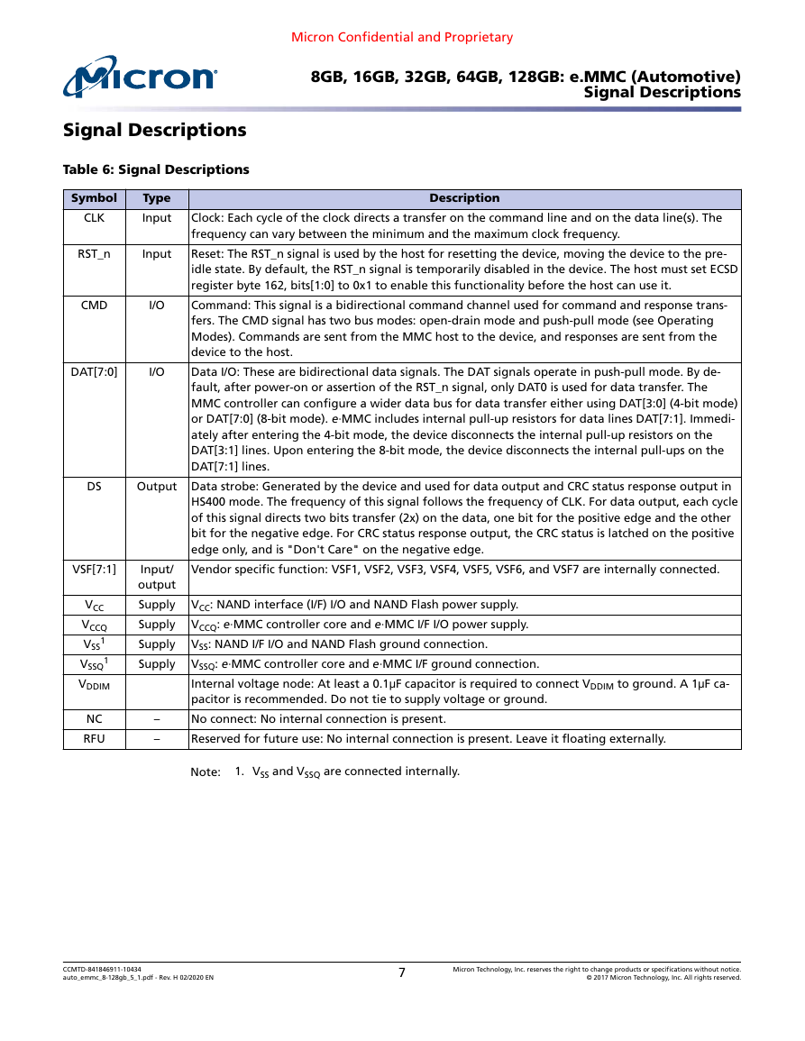
Table 6: Signal Descriptions
Symbol
CLK
Type
Input
RST_n
Input
CMD
I/O
DAT[7:0]
I/O
Description
Clock: Each cycle of the clock directs a transfer on the command line and on the data line(s). The
frequency can vary between the minimum and the maximum clock frequency.
Reset: The RST_n signal is used by the host for resetting the device, moving the device to the pre-
idle state. By default, the RST_n signal is temporarily disabled in the device. The host must set ECSD
register byte 162, bits[1:0] to 0x1 to enable this functionality before the host can use it.
Command: This signal is a bidirectional command channel used for command and response trans-
fers. The CMD signal has two bus modes: open-drain mode and push-pull mode (see Operating
Modes). Commands are sent from the MMC host to the device, and responses are sent from the
device to the host.
Data I/O: These are bidirectional data signals. The DAT signals operate in push-pull mode. By de-
fault, after power-on or assertion of the RST_n signal, only DAT0 is used for data transfer. The
MMC controller can configure a wider data bus for data transfer either using DAT[3:0] (4-bit mode)
or DAT[7:0] (8-bit mode). e·MMC includes internal pull-up resistors for data lines DAT[7:1]. Immedi-
ately after entering the 4-bit mode, the device disconnects the internal pull-up resistors on the
DAT[3:1] lines. Upon entering the 8-bit mode, the device disconnects the internal pull-ups on the
DAT[7:1] lines.
Output Data strobe: Generated by the device and used for data output and CRC status response output in
HS400 mode. The frequency of this signal follows the frequency of CLK. For data output, each cycle
of this signal directs two bits transfer (2x) on the data, one bit for the positive edge and the other
bit for the negative edge. For CRC status response output, the CRC status is latched on the positive
edge only, and is "Don't Care" on the negative edge.
Vendor specific function: VSF1, VSF2, VSF3, VSF4, VSF5, VSF6, and VSF7 are internally connected.
VCC: NAND interface (I/F) I/O and NAND Flash power supply.
VCCQ: e·MMC controller core and e·MMC I/F I/O power supply.
VSS: NAND I/F I/O and NAND Flash ground connection.
VSSQ: e·MMC controller core and e·MMC I/F ground connection.
Internal voltage node: At least a 0.1μF capacitor is required to connect VDDIM to ground. A 1μF ca-
pacitor is recommended. Do not tie to supply voltage or ground.
No connect: No internal connection is present.
Reserved for future use: No internal connection is present. Leave it floating externally.
Note:
1. VSS and VSSQ are connected internally.
DS
VSF[7:1]
VCC
VCCQ
1
VSS
1
VSSQ
VDDIM
NC
RFU
Input/
output
Supply
Supply
Supply
Supply
–
–
CCMTD-841846911-10434
auto_emmc_8-128gb_5_1.pdf - Rev. H 02/2020 EN
7
Micron Technology, Inc. reserves the right to change products or specifications without notice.
© 2017 Micron Technology, Inc. All rights reserved.
�
Micron Confidential and Proprietary
8GB, 16GB, 32GB, 64GB, 128GB: e.MMC (Automotive)
100-Ball Signal Assignments
100-Ball Signal Assignments
Figure 2: 100 Ball (Top View, Ball Down)
3
4
5
6
7
8
2
NC
1
NC
NC
9
NC
10
NC
NC
VSF1
VSF2
VSF3
VSF4
VSF5
VSF6
VSF7
VSF8
RFU
RFU
VDDIM
RFU
RFU
RFU
RFU
RFU
VCC
VCC
VCC
VCC
VCC
VCC
VCC
VCC
VSS
VSS
VSS
VSS
VSS
VSS
VSS
VSS
VSSQ
VCCQ
RFU
RFU
RFU
RFU
VCCQ
VSSQ
RFU
RFU
RFU
VSS
RFU
RFU
RFU
RFU
DAT0
DAT2
RFU
DS
RFU
RFU
DAT5
DAT7
VCCQ
VSSQ
VCCQ
RFU
RFU
VCCQ
VSSQ
VCCQ
RFU
RFU
VSSQ
RST_n
RFU
VSSQ
RFU
RFU
DAT1
DAT3
RFU
RFU
RFU
RFU
DAT4
DAT6
VSSQ
VCCQ
RFU
CMD
CLK
RFU
VCCQ
VSSQ
NC
NC
NC
NC
NC
NC
A
B
D
E
F
G
H
J
K
L
M
N
P
T
U
A
B
D
E
F
G
H
J
K
L
M
N
P
T
U
Notes:
1. Connect a 1μF decoupling capacitor from VDDIM to ground.
2. Some previous versions of the JEDEC product or mechanical specification had defined
reserved for future use (RFU) balls as no connect (NC) balls. NC balls assigned in the pre-
vious specifications could have been connected to ground on the system board. To ena-
ble new feature introduction, some of these balls are assigned as RFU in the v4.4 me-
chanical specification. Any new PCB footprint implementations should use the new ball
assignments and leave the RFU balls floating on the system board.
3. VCC, VCCQ, VSS, and VSSQ balls must all be connected on the system board.
CCMTD-841846911-10434
auto_emmc_8-128gb_5_1.pdf - Rev. H 02/2020 EN
8
Micron Technology, Inc. reserves the right to change products or specifications without notice.
© 2017 Micron Technology, Inc. All rights reserved.
�


 2023年江西萍乡中考道德与法治真题及答案.doc
 2012年重庆南川中考生物真题及答案.doc
 2013年江西师范大学地理学综合及文艺理论基础考研真题.doc
 2020年四川甘孜小升初语文真题及答案I卷.doc
 2020年注册岩土工程师专业基础考试真题及答案.doc
 2023-2024学年福建省厦门市九年级上学期数学月考试题及答案.doc
 2021-2022学年辽宁省沈阳市大东区九年级上学期语文期末试题及答案.doc
 2022-2023学年北京东城区初三第一学期物理期末试卷及答案.doc
 2018上半年江西教师资格初中地理学科知识与教学能力真题及答案.doc
 2012年河北国家公务员申论考试真题及答案-省级.doc
 2020-2021学年江苏省扬州市江都区邵樊片九年级上学期数学第一次质量检测试题及答案.doc
 2022下半年黑龙江教师资格证中学综合素质真题及答案.doc