Chinese Journal of Aeronautics 22(2009) 250-256
Chinese
Journal of
Aeronautics
www.elsevier.com/locate/cja
Design of Flight Control System for a Small
Unmanned Tilt Rotor Aircraft
Song Yanguo*, Wang Huanjin
National Key Laboratory of Rotorcraft Aeromechanics, College of Aerospace Engineering,
Nanjing University of Aeronautics and Astronautics, Nanjing 210016, China
Received 23 May 2008; accepted 25 March 2009
Abstract
A tilt rotor is an aircraft of a special kind, which possesses the characteristics of a helicopter and a fixed-wing airplane. How-
ever, there are a great number of important technical problems waiting for settlements. Of them, the flight control system might
be a critical one. This article presents the progresses of the research work on the design of flight control system at Nanjing Uni-
versity of Aeronautics and Astronautics (NUAA). The flight control law of the tilt rotor aircraft is designed with the help of an
inner/outer loop control structure and an eigenstructure assignment algorithm on the basis of a proper mathematical model al-
ready verified by the wind tunnel tests. The proposed control law has been born out through the construction of the flight control
system and the flight tests. Now, the flight tests are still underway on a prototype of small unmanned tilt rotor aircraft. The results
have evidenced the credibility of the aircraft design and the effectiveness of the flight control system for the tilt rotor working in
the helicopter mode. A full envelope flight test is planned to carry out further researches on the flight control law.
Keywords: tilt rotor aircraft; control; aircraft models; flight dynamics
1. Introduction1
A growing number of countries have been paying
close attention to the development of tilt rotor aircraft,
which combines the vertical lift ability of helicopters
and the speed and range of fixed-wing airplanes[1-6] and
has found wide applications in both military and civil
fields.
The critical technological problem that is facing de-
signers and researchers of tilt rotor aircrafts is design
of flight control system. To find out the solution, a
prototype of small unmanned tilt rotor aircraft has been
designed and constructed, and a model for wind tunnel
tests has been made to throw light on its aerodynamic
performance. And the wind tunnel test results have
been used to verify and improve the mathematical
model. Based on this mathematical model, an in-
ner/outer loop control structure and an eigenstructure
assignment algorithm are used to design the tilt rotor
flight control law. The proposed control law is verified
through construction of a flight control system and
*Corresponding author. Tel.: +86-25-84895973.
E-mail address: songyg@nuaa.edu.cn
Foundation item: National Natural Science Foundation of China
(60705034)
1000-9361/$ - see front matter © 2009 Elsevier Ltd. All rights reserved.
doi: 10.1016/S1000-9361(08)60095-3
accomplishment of flight tests, which are being under-
way.
The design of flight control law plays an significant
role in future research on the development of this kind
of aircraft. This article will make a concise introduc-
tion to the progresses of the work on it at Nanjing
University of Aeronautics and Astronautics (NUAA).
2. Mathematical Modeling of Flight Dynamics
In modeling tilt rotor flight dynamics, as a tool of
utmost importance, the aerodynamic model of rotor
must include the aerodynamic model of aerofoil, the
induced velocity model, and the blade flapping model.
For the details of calculating the aerodynamic forces of
a rotor, one can refer to Refs.[7-8]. In order to ensure
the real-time calculation of a flight dynamics model,
an aerodynamic interference coefficient is introduced
to consider the disturbance between the rotor and the
wing. According to the analysis of wind tunnel test
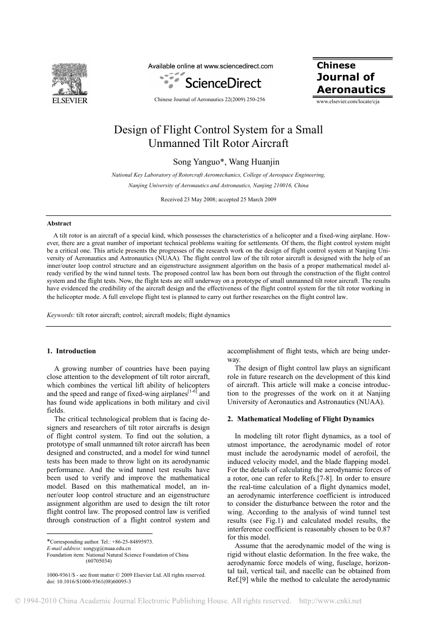
results (see Fig.1) and calculated model results, the
interference coefficient is reasonably chosen to be 0.87
for this model.
Assume that the aerodynamic model of the wing is
rigid without elastic deformation. In the free wake, the
aerodynamic force models of wing, fuselage, horizon-
tal tail, vertical tail, and nacelle can be obtained from
Ref.[9] while the method to calculate the aerodynamic
�
No.3
Song Yanguo et al. / Chinese Journal of Aeronautics 22(2009) 250-256
· 251 ·
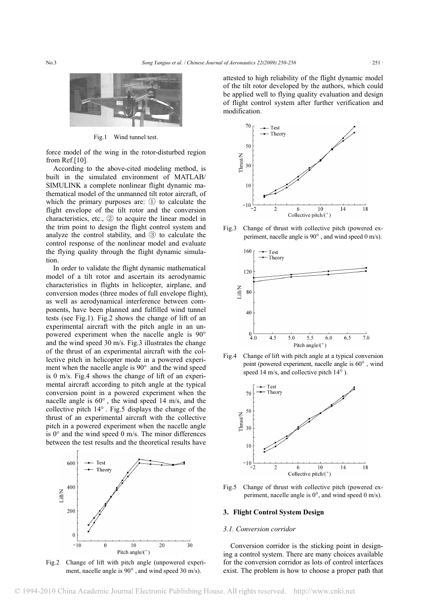
attested to high reliability of the flight dynamic model
of the tilt rotor developed by the authors, which could
be applied well to flying quality evaluation and design
of flight control system after further verification and
modification.
Fig.1 Wind tunnel test.
force model of the wing in the rotor-disturbed region
from Ref.[10].
According to the above-cited modeling method, is
built in the simulated environment of MATLAB/
SIMULINK a complete nonlinear flight dynamic ma-
thematical model of the unmanned tilt rotor aircraft, of
which the primary purposes are: ① to calculate the
flight envelope of the tilt rotor and the conversion
characteristics, etc., ② to acquire the linear model in
the trim point to design the flight control system and
analyze the control stability, and ③ to calculate the
control response of the nonlinear model and evaluate
the flying quality through the flight dynamic simula-
tion.
In order to validate the flight dynamic mathematical
model of a tilt rotor and ascertain its aerodynamic
characteristics in flights in helicopter, airplane, and
conversion modes (three modes of full envelope flight),
as well as aerodynamical interference between com-
ponents, have been planned and fulfilled wind tunnel
tests (see Fig.1). Fig.2 shows the change of lift of an
experimental aircraft with the pitch angle in an un-
powered experiment when the nacelle angle is 90°
and the wind speed 30 m/s. Fig.3 illustrates the change
of the thrust of an experimental aircraft with the col-
lective pitch in helicopter mode in a powered experi-
ment when the nacelle angle is 90° and the wind speed
is 0 m/s. Fig.4 shows the change of lift of an experi-
mental aircraft according to pitch angle at the typical
conversion point in a powered experiment when the
nacelle angle is 60° , the wind speed 14 m/s, and the
collective pitch 14° . Fig.5 displays the change of the
thrust of an experimental aircraft with the collective
pitch in a powered experiment when the nacelle angle
is 0° and the wind speed 0 m/s. The minor differences
between the test results and the theoretical results have
Fig.3 Change of thrust with collective pitch (powered ex-
periment, nacelle angle is 90° , and wind speed 0 m/s).
Fig.4 Change of lift with pitch angle at a typical conversion
point (powered experiment, nacelle angle is 60° , wind
speed 14 m/s, and collective pitch 14° ).
Fig.5 Change of thrust with collective pitch (powered ex-
periment, nacelle angle is 0°, and wind speed 0 m/s).
3. Flight Control System Design
3.1. Conversion corridor
Fig.2 Change of lift with pitch angle (unpowered experi-
ment, nacelle angle is 90° , and wind speed 30 m/s).
Conversion corridor is the sticking point in design-
ing a control system. There are many choices available
for the conversion corridor as lots of control interfaces
exist. The problem is how to choose a proper path that
�
· 252 ·
Song Yanguo et al. / Chinese Journal of Aeronautics 22(2009) 250-256
No.3
ensures the safety and control simplicity in conversion.
The principle of choosing conversion corridor in this
example is described as follows: the pitch angle of an
aircraft should make slow changes at low speeds.
When the aircraft’s forward speed gradually increases,
as all of the control interfaces start working, the pitch
angle could be kept fixed in the vicinity of a given
value. This is done for two purposes: one is to make
the conversion flight of the aircraft as stable as possi-
ble and the other is to provide guidance for designing
the flight control system. The conversion characteris-
tics should be optimized by the experience from
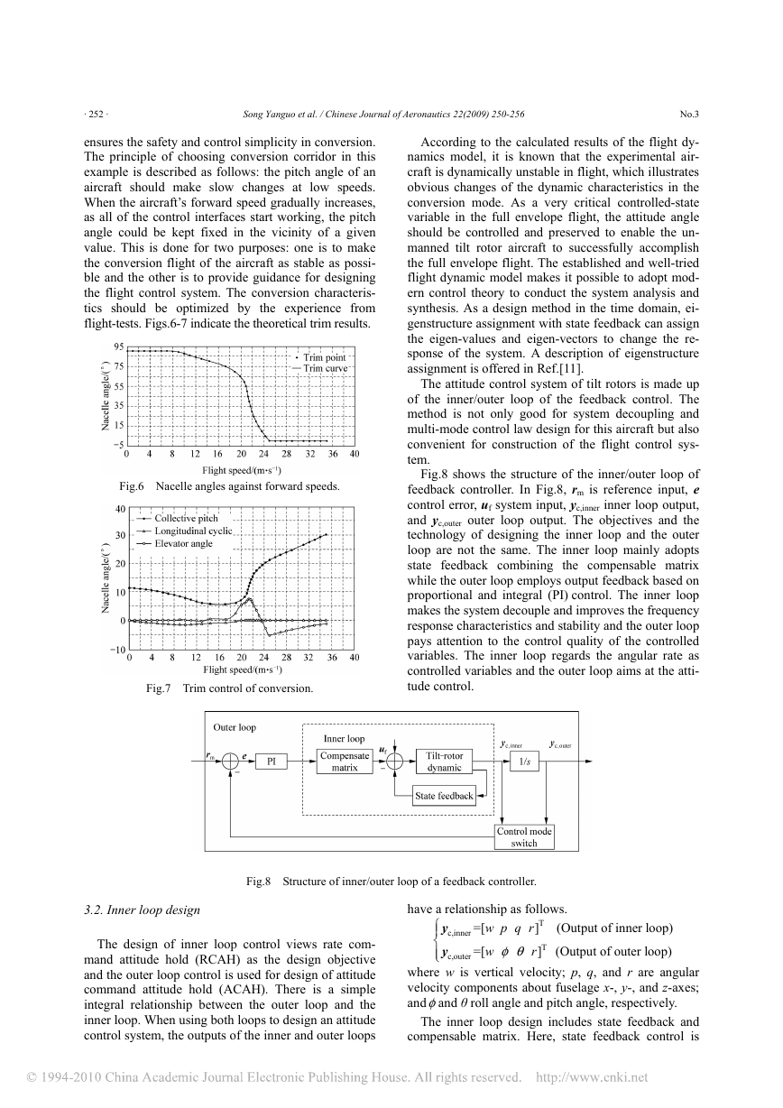
flight-tests. Figs.6-7 indicate the theoretical trim results.
Fig.6 Nacelle angles against forward speeds.
Fig.7 Trim control of conversion.
According to the calculated results of the flight dy-
namics model, it is known that the experimental air-
craft is dynamically unstable in flight, which illustrates
obvious changes of the dynamic characteristics in the
conversion mode. As a very critical controlled-state
variable in the full envelope flight, the attitude angle
should be controlled and preserved to enable the un-
manned tilt rotor aircraft to successfully accomplish
the full envelope flight. The established and well-tried
flight dynamic model makes it possible to adopt mod-
ern control theory to conduct the system analysis and
synthesis. As a design method in the time domain, ei-
genstructure assignment with state feedback can assign
the eigen-values and eigen-vectors to change the re-
sponse of the system. A description of eigenstructure
assignment is offered in Ref.[11].
The attitude control system of tilt rotors is made up
of the inner/outer loop of the feedback control. The
method is not only good for system decoupling and
multi-mode control law design for this aircraft but also
convenient for construction of the flight control sys-
tem.
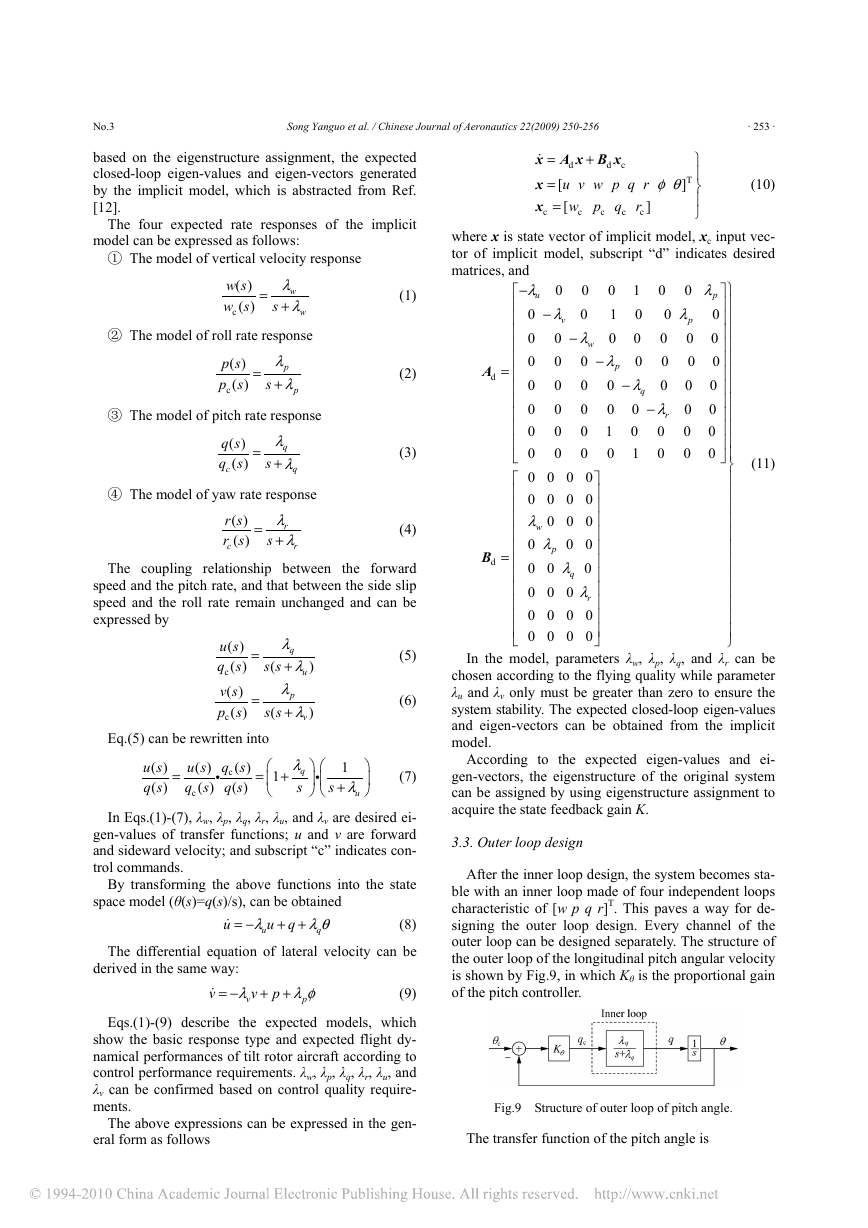
Fig.8 shows the structure of the inner/outer loop of
feedback controller. In Fig.8, rm is reference input, e
control error, uf system input, yc,inner inner loop output,
and yc,outer outer loop output. The objectives and the
technology of designing the inner loop and the outer
loop are not the same. The inner loop mainly adopts
state feedback combining the compensable matrix
while the outer loop employs output feedback based on
proportional and integral (PI) control. The inner loop
makes the system decouple and improves the frequency
response characteristics and stability and the outer loop
pays attention to the control quality of the controlled
variables. The inner loop regards the angular rate as
controlled variables and the outer loop aims at the atti-
tude control.
Fig.8 Structure of inner/outer loop of a feedback controller.
have a relationship as follows.
y
c,inner
y
c,outer
T
w p q r
=[
]
rφ θ
T
w
=[
]
(Output of inner loop)
(Output of outer loop)
⎧⎪
⎨
⎪⎩
where w is vertical velocity; p, q, and r are angular
velocity components about fuselage x-, y-, and z-axes;
andφand θ roll angle and pitch angle, respectively.
The inner loop design includes state feedback and
compensable matrix. Here, state feedback control is
3.2. Inner loop design
The design of inner loop control views rate com-
mand attitude hold (RCAH) as the design objective
and the outer loop control is used for design of attitude
command attitude hold (ACAH). There is a simple
integral relationship between the outer loop and the
inner loop. When using both loops to design an attitude
control system, the outputs of the inner and outer loops
�
No.3
Song Yanguo et al. / Chinese Journal of Aeronautics 22(2009) 250-256
· 253 ·
based on the eigenstructure assignment, the expected
closed-loop eigen-values and eigen-vectors generated
by the implicit model, which is abstracted from Ref.
[12].
The four expected rate responses of the implicit
model can be expressed as follows:
① The model of vertical velocity response
w s
( )
w s
( )
c
=
λ
w
λ
+
w
s
(1)
② The model of roll rate response
p s
( )
p s
( )
c
=
λ
p
+
λ
p
s
(2)
③ The model of pitch rate response
q s
( )
q s
( )
c
=
λ
q
+
λ
q
s
(3)
④ The model of yaw rate response
=
r s
( )
r s
( )
c
λ
r
+
λ
r
s
(4)
The coupling relationship between the forward
speed and the pitch rate, and that between the side slip
speed and the roll rate remain unchanged and can be
expressed by
u s
( )
q s
( )
c
v s
( )
p s
( )
c
=
=
(5)
(6)
s s
(
λ
q
+
λ
p
+
λ
)
u
λ
)
v
s s
(
Eq.(5) can be rewritten into
u s
( )
q s
( )
=
u s
( )
q s
( )
c
i
q s
( )
c
q s
( )
=
⎛
⎜
⎝
+
1
λ
q
s
⎛
⎞
i
⎜
⎟
⎠ ⎝
1
λ
+
u
⎞
⎟
⎠
s
(7)
In Eqs.(1)-(7), λw, λp, λq, λr, λu, and λv are desired ei-
gen-values of transfer functions; u and v are forward
and sideward velocity; and subscript “c” indicates con-
trol commands.
By transforming the above functions into the state
space model (θ(s)=q(s)/s), can be obtained
(8)
The differential equation of lateral velocity can be
+ +
u qλ
u
λθ
q
= −
u
derived in the same way:
v
= −
+ +
pλ
v
v
λφ
p
(9)
Eqs.(1)-(9) describe the expected models, which
show the basic response type and expected flight dy-
namical performances of tilt rotor aircraft according to
control performance requirements. λw, λp, λq, λr, λu, and
λv can be confirmed based on control quality require-
ments.
The above expressions can be expressed in the gen-
eral form as follows
c
+
x A x B x
d
x
x
=
d
=
u v w p q r
[
=
w p q r
]
[
c
c
c
c
c
φθ
T
]
⎫
⎪
⎬
⎪
⎭
(10)
−
=
−
−
−
A
d
0
λ
v
0
0
0
0
0
0
0
0
0
0
0
λ
r
0
0
0
1
0
λ
p
0
0
1
0
0
λ
p
0
0
0
0
0
0
λ
p
0
0
0
0
0
0
0
1
0
0
0
λ
q
−
0
0
1
where x is state vector of implicit model, xc input vec-
tor of implicit model, subscript “d” indicates desired
matrices, and
−⎡
λ
0
u
⎢
0
0
⎢
⎢
λ
0
w
⎢
0
0
⎢
⎢
0
0
⎢
⎢
0
0
⎢
⎢
0
0
⎢
0
0
⎣
0 0 0 0
⎤
⎡
⎥
⎢
0 0 0 0
⎥
⎢
λ
0 0 0
⎥
⎢
w
⎢
⎥
λ
0
0 0
⎥
⎢
p
= ⎢
⎥
λ
0 0
0
⎢
⎥
q
λ
⎢
⎥
0 0 0
r
⎥
⎢
0 0 0 0
⎢
⎥
⎢
⎥
0 0 0 0
⎦
⎣
⎫
⎤
⎪
⎥
⎪
⎥
⎪
⎥
⎪
⎥
⎪
⎥
⎪
⎥
⎪
⎥
⎪
⎥
⎪
⎥
⎪
⎥
⎪
⎥
⎪
⎦⎬
⎪
⎪
⎪
⎪
⎪
⎪
⎪
⎪
⎪
⎪
⎪
⎪
⎭
(11)
In the model, parameters λw, λp, λq, and λr can be
chosen according to the flying quality while parameter
λu and λv only must be greater than zero to ensure the
system stability. The expected closed-loop eigen-values
and eigen-vectors can be obtained from the implicit
model.
According to the expected eigen-values and ei-
gen-vectors, the eigenstructure of the original system
can be assigned by using eigenstructure assignment to
acquire the state feedback gain K.
B
d
3.3. Outer loop design
After the inner loop design, the system becomes sta-
ble with an inner loop made of four independent loops
characteristic of [w p q r]T. This paves a way for de-
signing the outer loop design. Every channel of the
outer loop can be designed separately. The structure of
the outer loop of the longitudinal pitch angular velocity
is shown by Fig.9, in which Kθ is the proportional gain
of the pitch controller.
Fig.9 Structure of outer loop of pitch angle.
The transfer function of the pitch angle is
�
· 254 ·
Song Yanguo et al. / Chinese Journal of Aeronautics 22(2009) 250-256
No.3
θ
s
( )
θ
s
( )
c
=
λ
K
θ
q
λ
λ
+
s K
θ
q
q
+
2
s
(12)
The transfer function of the roll angle can be ex-
pressed likewise. And the transfer function of the yaw
angle is
φ
s
( )
φ
s
( )
c
=
+
2
s
λ
K
φ
p
λ
λ
+
s K
φ
p
p
(13)
where Kφis the proportional gain of the roll controller.
In the above transfer functions, the parameters λp
and λq have already been attained in the inner loop
design and the parameters Kθ and Kφshould be deter-
mined by flight performance in the outer loop design.
Figs.10-11 show the simulation results in the conver-
sion mode, when the nacelle angle is 55°.
Fig.10 Pitch angle response under unit step pitch angle
input (nacelle angle is 55° ).
Fig.11 Roll angle response under unit step roll angle input
(nacelle angle is 55° ).
3.4. Construction of flight control system
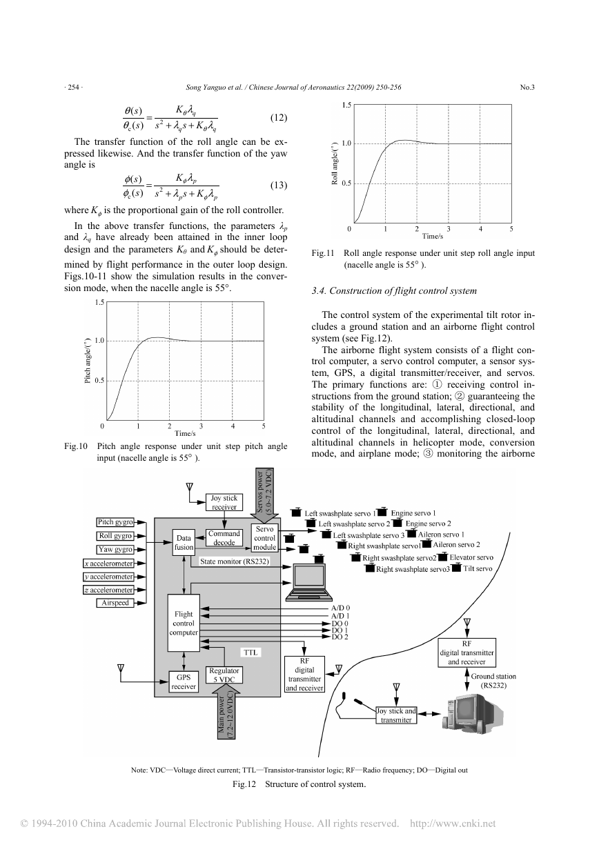
The control system of the experimental tilt rotor in-
cludes a ground station and an airborne flight control
system (see Fig.12).
The airborne flight system consists of a flight con-
trol computer, a servo control computer, a sensor sys-
tem, GPS, a digital transmitter/receiver, and servos.
The primary functions are: ① receiving control in-
structions from the ground station; ② guaranteeing the
stability of the longitudinal, lateral, directional, and
altitudinal channels and accomplishing closed-loop
control of the longitudinal, lateral, directional, and
altitudinal channels in helicopter mode, conversion
mode, and airplane mode; ③ monitoring the airborne
Note: VDC—Voltage direct current; TTL—Transistor-transistor logic; RF—Radio frequency; DO—Digital out
Fig.12 Structure of control system.
�
No.3
Song Yanguo et al. / Chinese Journal of Aeronautics 22(2009) 250-256
· 255 ·
system performance; ④ transmitting flight data to the
ground station so as to replay, edit, and analyze them
after the experiments; ⑤ controlling rotation speed of
the engine; and ⑥ estimating the flight state of the
unmanned tilt rotor aircraft.
The ground station includes a joy stick, a ground
station computer, and a digital transmitter/receiver. The
joy stick serves the interface transmitting the opera-
tor’s instructions; the ground station computer mainly
monitors flight states; and the digital transmitter sends
and the receiver receives commands and flight data.
4. Program of Experimental Research
In order to validate the proposed technology, a pro-
totype of a small unmanned tilt rotor was chosen to be
manufactured for reducing the research risk, shorten-
ing the research period, and saving the research cost.
The flight speed of the experimental aircraft in airplane
mode was minimized enough to satisfy the require-
ments for visual manipulation in initial flight tests.
Technically ripe engine, actuator, and others were
adopted to ensure the planned research progress rate
and reliability. Full use of existing testing conditions
was made to verify every technological detail of the
experimental aircraft with the purpose of realizing ver-
tical taking-off and landing, hovering in helicopter
mode, and flying in conversion mode and airplane
mode.
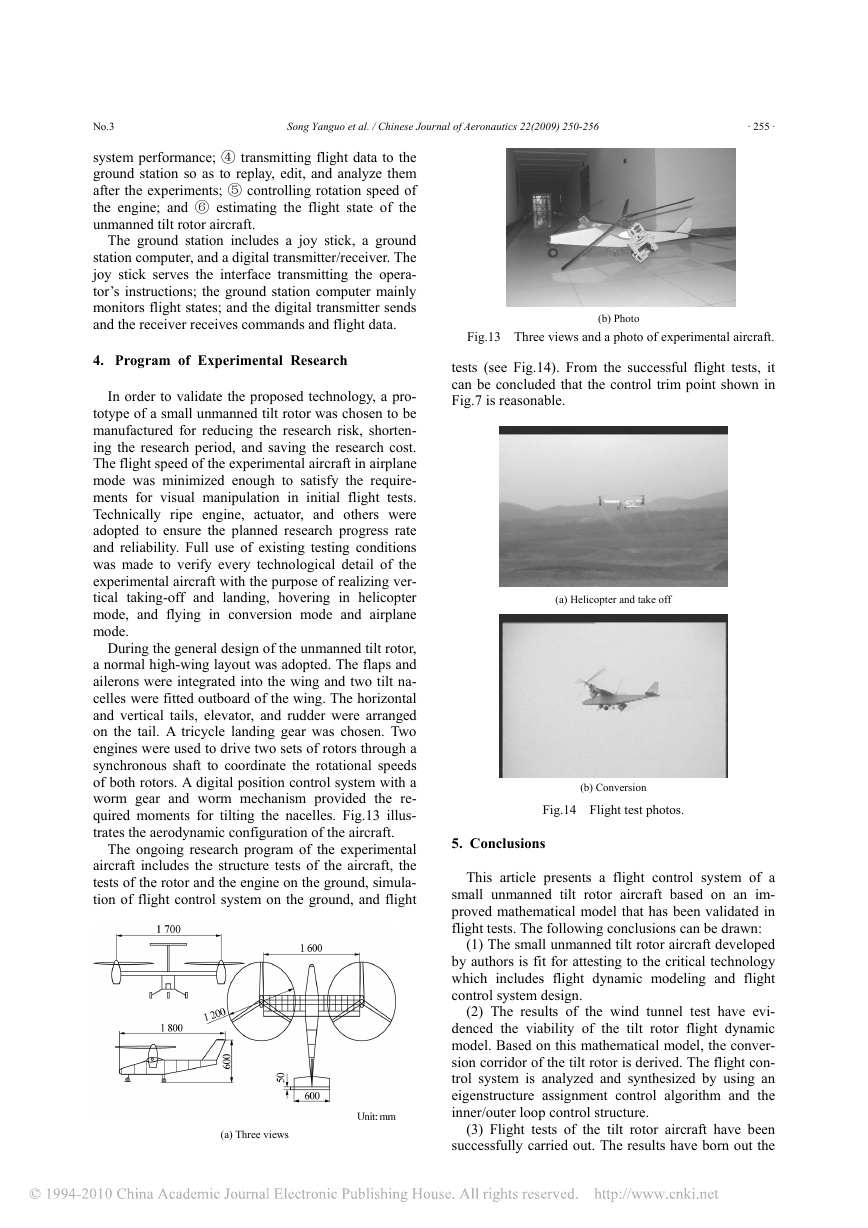
During the general design of the unmanned tilt rotor,
a normal high-wing layout was adopted. The flaps and
ailerons were integrated into the wing and two tilt na-
celles were fitted outboard of the wing. The horizontal
and vertical tails, elevator, and rudder were arranged
on the tail. A tricycle landing gear was chosen. Two
engines were used to drive two sets of rotors through a
synchronous shaft to coordinate the rotational speeds
of both rotors. A digital position control system with a
worm gear and worm mechanism provided the re-
quired moments for tilting the nacelles. Fig.13 illus-
trates the aerodynamic configuration of the aircraft.
The ongoing research program of the experimental
aircraft includes the structure tests of the aircraft, the
tests of the rotor and the engine on the ground, simula-
tion of flight control system on the ground, and flight
(a) Three views
(b) Photo
Fig.13 Three views and a photo of experimental aircraft.
tests (see Fig.14). From the successful flight tests, it
can be concluded that the control trim point shown in
Fig.7 is reasonable.
(a) Helicopter and take off
(b) Conversion
Fig.14 Flight test photos.
5. Conclusions
This article presents a flight control system of a
small unmanned tilt rotor aircraft based on an im-
proved mathematical model that has been validated in
flight tests. The following conclusions can be drawn:
(1) The small unmanned tilt rotor aircraft developed
by authors is fit for attesting to the critical technology
which includes flight dynamic modeling and flight
control system design.
(2) The results of the wind tunnel test have evi-
denced the viability of the tilt rotor flight dynamic
model. Based on this mathematical model, the conver-
sion corridor of the tilt rotor is derived. The flight con-
trol system is analyzed and synthesized by using an
eigenstructure assignment control algorithm and the
inner/outer loop control structure.
(3) Flight tests of the tilt rotor aircraft have been
successfully carried out. The results have born out the
�
· 256 ·
Song Yanguo et al. / Chinese Journal of Aeronautics 22(2009) 250-256
No.3
credibility of the aircraft design and the effectiveness
of the flight control system in controlling the tilt rotor
in helicopter mode.
(4) A full envelope flight test is planned to research
the flight control law.
References
[1] Hathaway E L, Gandhi F. Tiltrotor whirl flutter allevia-
tion using actively controlled wing flaperons. AIAA
Journal 2006; 44(11): 2524-2524.
[2] Burgess R R. Eagle eye tiltrotor UAV will bolster coast
guard’s sea search capability. Sea Power 2004; 47(5):
27-30.
[3] Carlson E B, Zhao Y Y J. Optimal city-center takeoff
operation of tiltrotor aircraft in one engine failure.
Journal of Aerospace Engineering 2004; 17(1): 26-39.
[4] Ghiringhelli G L, Masarati P, Mantegazza P, et al.
tiltrotor configuration.
Multi-body analysis of a
Non-linear Dynamics 1999; 19(4): 333-357.
[5] Phillips E H. Bell’s BA609 tiltrotor program on sched-
ule. Aviation Week & Space Technology 2001; 154(7):
56.
[6] Phillips E H. Full tilt for BA609. Aviation Week &
Space Technology 2005; 162(12): 32-33.
[7] Wang S C. Helicopter aerodynamic. PhD thesis, Nan-
jing University of Aeronautics and Astronautics, 1993.
[in Chinese]
[8] Gao Z, Chen R L. Helicopter flight dynamics. Beijing,
Science Press, 2003.[in Chinese]
[9] Xiong H Q, Liu C, Zheng B W. Aircraft flight dynam-
ics. Beijing: Aviation Industry Press, 1990. [in Chinese]
[10] Ferguson S W. A mathematical model for real time
flight simulation of a generic tilt rotor aircraft. NASA
CR-166536, 1988.
[11] Sobel K M, Shapiro E Y, Andry A N. Eigenstructure
assignment. International Journal of Control 1994;
59(1): 13-37.
[12] ADS-33E-PRF Aeronautical design standard perform-
ance specification handling qualities requirements for
military rotorcraft. 2000.
Biography:
Song Yanguo Born in 1973, he graduated and earned Ph. D.
degree in flight dynamics and flight control from Nanjing
University of Aeronautics and Astronautics (NUAA) in
2003. He is currently an associate professor at NUAA, with
academic interest in UAV flight control and UAV design.
E-mail: songyg@nuaa.edu.cn
小型无人倾转旋翼机飞行控制系统设计
宋彦国 王焕瑾
(南京航空航天大学航空宇航学院,直升机旋翼动力学国家级重点实验室)
摘 要:倾转旋翼飞行器是一种独特的新构型飞行器,兼具固定翼飞机和直升机双重飞行模式和优点。但是,这种
飞行器仍有许多关键技术需要解决,飞行控制系统是其中之一。本文介绍了南航所做的小型无人倾转旋翼机飞行控
制系统技术研究的主要内容。研究工作建立在良好的飞行力学数学模型基础上,这一模型经风洞吹风试验进行了验
证。控制律设计采用内外环控制结构和节点配置方法。这一控制律设计通过飞行控制系统的实现和飞行试验进行了
验证。目前,飞行试验仍在进行,已有数据验证了模型的可靠性和直升机模式飞行控制律设计的有效性。下面将继
续进行全飞行包线的飞行试验来进一步研究飞行控制律。
关键词:垂直/短距起降飞行器; 控制; 飞行器模型; 飞行动力学
Erratum to “Uniform Coverage of Fibres over Open-contoured Free-
form Structure Based on Arc-length Parameter”
[Chinese Journal of Aeronautics 21(2008)571-577]
Wang Xiaoping*, An Luling, Zhang Liyan, Zhou Laishui
Jiangsu Key Laboratory of Precision and Macro-manufacturing Technology, Nanjing University of Aeronautics and Astronautics,
Nanjing 210016, China
It is regretted that the author corrections requested at the proof stage were not made accurately. There are some
incorrect typings in two equations which will lead to inaccurate results if readers perform calculations directly with
them.
Actually , the vector “N(s)” in equations (8) and (12) should be changed into “Su×Sv”.
Readers who still have questions could contact the corresponding author:
Tel: +86-25-84891678
E-mail address: levine@nuaa.edu.cn
�


 2023年江西萍乡中考道德与法治真题及答案.doc
 2012年重庆南川中考生物真题及答案.doc
 2013年江西师范大学地理学综合及文艺理论基础考研真题.doc
 2020年四川甘孜小升初语文真题及答案I卷.doc
 2020年注册岩土工程师专业基础考试真题及答案.doc
 2023-2024学年福建省厦门市九年级上学期数学月考试题及答案.doc
 2021-2022学年辽宁省沈阳市大东区九年级上学期语文期末试题及答案.doc
 2022-2023学年北京东城区初三第一学期物理期末试卷及答案.doc
 2018上半年江西教师资格初中地理学科知识与教学能力真题及答案.doc
 2012年河北国家公务员申论考试真题及答案-省级.doc
 2020-2021学年江苏省扬州市江都区邵樊片九年级上学期数学第一次质量检测试题及答案.doc
 2022下半年黑龙江教师资格证中学综合素质真题及答案.doc