EnDat (English) Version 2.2
Schnittstelle
EnDat Interface
VERSION 2.2
Bidirectional Synchronous-Serial
Interface for
Position Encoders
!
6
1
0
6
1
O
S
I
r
o
f
k
r
a
m
n
o
i
t
c
e
t
o
r
p
e
h
t
e
t
o
N
Edited on: Description of interface revised => See Topic 4.11: History of Revisions
Created
Lechner A.
03.07.2007
11 8 41
Responsible
Strasser E.
03.07.2007
00 00 00
Released
Strasser E. D297403
19.07.2007
13 29 26
Version Rev. Sheet Page
- 03 - B - 02 1/
131
Document no.
Release-No.
F93889
Name
Date
�
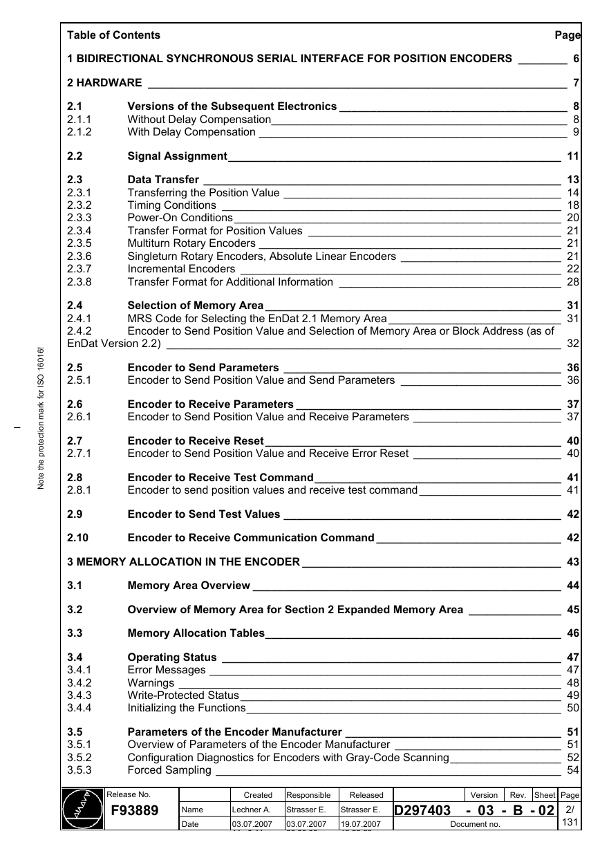
Table of Contents
Page
1 BIDIRECTIONAL SYNCHRONOUS SERIAL INTERFACE FOR POSITION ENCODERS ________ 6
2 HARDWARE ____________________________________________________________________ 7
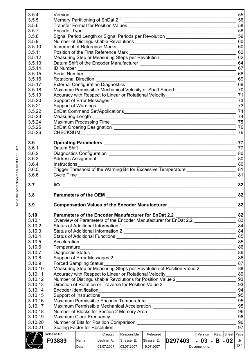
2.1
2.1.1
2.1.2
2.2
2.3
2.3.1
2.3.2
2.3.3
2.3.4
2.3.5
2.3.6
2.3.7
2.3.8
Versions of the Subsequent Electronics _____________________________________ 8
Without Delay Compensation________________________________________________ 8
With Delay Compensation __________________________________________________ 9
Signal Assignment______________________________________________________ 11
Data Transfer __________________________________________________________ 13
Transferring the Position Value _____________________________________________ 14
Timing Conditions _______________________________________________________ 18
Power-On Conditions_____________________________________________________ 20
Transfer Format for Position Values _________________________________________ 21
Multiturn Rotary Encoders _________________________________________________ 21
Singleturn Rotary Encoders, Absolute Linear Encoders __________________________ 21
Incremental Encoders ____________________________________________________ 22
Transfer Format for Additional Information ____________________________________ 28
2.4
2.4.1
2.4.2
EnDat Version 2.2) ________________________________________________________________ 32
Selection of Memory Area________________________________________________ 31
MRS Code for Selecting the EnDat 2.1 Memory Area ____________________________ 31
Encoder to Send Position Value and Selection of Memory Area or Block Address (as of
2.5
2.5.1
2.6
2.6.1
2.7
2.7.1
2.8
2.8.1
Encoder to Send Parameters _____________________________________________ 36
Encoder to Send Position Value and Send Parameters __________________________ 36
Encoder to Receive Parameters ___________________________________________ 37
Encoder to Send Position Value and Receive Parameters ________________________ 37
Encoder to Receive Reset________________________________________________ 40
Encoder to Send Position Value and Receive Error Reset ________________________ 40
Encoder to Receive Test Command________________________________________ 41
Encoder to send position values and receive test command _______________________ 41
2.9
Encoder to Send Test Values _____________________________________________ 42
2.10
Encoder to Receive Communication Command ______________________________ 42
3 MEMORY ALLOCATION IN THE ENCODER __________________________________________ 43
3.1
Memory Area Overview __________________________________________________ 44
Overview of Memory Area for Section 2 Expanded Memory Area _______________ 45
3.2
3.3
Memory Allocation Tables________________________________________________ 46
!
6
1
0
6
1
O
S
I
r
o
f
k
r
a
m
n
o
i
t
c
e
t
o
r
p
e
h
t
e
t
o
N
3.4
3.4.1
3.4.2
3.4.3
3.4.4
3.5
3.5.1
3.5.2
3.5.3
Operating Status _______________________________________________________ 47
Error Messages _________________________________________________________ 47
Warnings ______________________________________________________________ 48
Write-Protected Status____________________________________________________ 49
Initializing the Functions___________________________________________________ 50
Parameters of the Encoder Manufacturer ___________________________________ 51
Overview of Parameters of the Encoder Manufacturer ___________________________ 51
Configuration Diagnostics for Encoders with Gray-Code Scanning__________________ 52
Forced Sampling ________________________________________________________ 54
Release No.
F93889
Name
Date
Created Responsible
Strasser E.
03.07.2007
00 00 00
Lechner A.
03.07.2007
11 8 41
Released
Strasser E. D297403
19.07.2007
13 29 26
Version Rev. Sheet Page
- 03 - B - 02 2/
131
Document no.
�
!
6
1
0
6
1
O
S
I
r
o
f
k
r
a
m
n
o
i
t
c
e
t
o
r
p
e
h
t
e
t
o
N
3.5.4
3.5.5
3.5.6
3.5.7
3.5.8
3.5.9
3.5.10
3.5.11
3.5.12
3.5.13
3.5.14
3.5.15
3.5.16
3.5.17
3.5.18
3.5.19
3.5.20
3.5.21
3.5.22
3.5.23
3.5.24
3.5.25
3.5.26
3.6
3.6.1
3.6.2
3.6.3
3.6.4
3.6.5
3.6.6
3.7
3.8
Version________________________________________________________________ 55
Memory Partitioning of EnDat 2.1 ___________________________________________ 56
Transfer Format for Position Values _________________________________________ 58
Encoder Type___________________________________________________________ 58
Signal Period Length or Signal Periods per Revolution ___________________________ 59
Number of Distinguishable Revolutions _______________________________________ 60
Increment of Reference Marks______________________________________________ 60
Position of the First Reference Mark _________________________________________ 62
Measuring Step or Measuring Steps per Revolution _____________________________ 62
Datum Shift of the Encoder Manufacturer _____________________________________ 64
ID Number _____________________________________________________________ 67
Serial Number __________________________________________________________ 68
Rotational Direction ______________________________________________________ 69
External Configuration Diagnostics __________________________________________ 69
Maximum Permissible Mechanical Velocity or Shaft Speed _______________________ 70
Accuracy with Respect to Linear or Rotational Velocity___________________________ 71
Support of Error Messages 1 _______________________________________________ 73
Support of Warnings _____________________________________________________ 73
EnDat Command Set/Applications___________________________________________ 74
Measuring Length _______________________________________________________ 74
Maximum Processing Time ________________________________________________ 75
EnDat Ordering Designation _______________________________________________ 76
CHECKSUM____________________________________________________________ 76
Operating Parameters ___________________________________________________ 77
Datum Shift ____________________________________________________________ 77
Diagnostics Configuration _________________________________________________ 80
Address Assignment _____________________________________________________ 80
Instructions_____________________________________________________________ 80
Trigger Threshold of the Warning Bit for Excessive Temperature ___________________ 81
Cycle Time _____________________________________________________________ 81
I/O ___________________________________________________________________ 82
Parameters of the OEM __________________________________________________ 82
3.9
3.10
3.10.1
3.10.2
3.10.3
3.10.4
3.10.5
3.10.6
3.10.7
3.10.8
3.10.9
3.10.10
3.10.11
3.10.12
3.10.13
3.10.14
3.10.15
3.10.16
3.10.17
3.10.18
3.10.19
3.10.20
3.10.21
Compensation Values of the Encoder Manufacturer __________________________ 82
Parameters of the Encoder Manufacturer for EnDat 2.2 _______________________ 82
Overview of Parameters of the Encoder Manufacturer for EnDat 2.2 ________________ 83
Status of Additional Information 1 ___________________________________________ 84
Status of Additional Information 2 ___________________________________________ 84
Status of Additional Functions ______________________________________________ 85
Acceleration ____________________________________________________________ 85
Temperature____________________________________________________________ 86
Diagnostic Status ________________________________________________________ 86
Support of Error Messages 2 _______________________________________________ 86
Forced Sampling Status___________________________________________________ 87
Measuring Step or Measuring Steps per Revolution of Position Value 2______________ 88
Accuracy with Respect to Linear or Rotational Velocity___________________________ 89
Number of Distinguishable Revolutions for Position Value 2 _______________________ 93
Direction of Rotation or Traverse for Position Value 2 ____________________________ 93
Encoder Identification_____________________________________________________ 94
Support of Instructions ____________________________________________________ 95
Maximum Permissible Encoder Temperature __________________________________ 95
Maximum Permissible Mechanical Acceleration ________________________________ 95
Number of Blocks for Section 2 Memory Area __________________________________ 96
Maximum Clock Frequency ________________________________________________ 96
Number of Bits for Position Comparison ______________________________________ 96
Scaling Factor for Resolution_______________________________________________ 97
Version Rev. Sheet Page
- 03 - B - 02 3/
131
Released
Strasser E. D297403
19.07.2007
13 29 26
Name
Date
Created Responsible
Strasser E.
03.07.2007
00 00 00
Lechner A.
03.07.2007
11 8 41
Release No.
F93889
Document no.
�
3.10.22
Period
3.10.23
3.10.24
3.10.25
3.10.26
3.10.27
Measuring Step, or Measuring Steps per Revolution or Subdivision Values of a Grating
97
Maximum Speed or RPM for Constant Code Value______________________________ 98
Offset Between Position Value and Position Value 2_____________________________ 99
"Number of Distinguishable Revolutions" with Scaling Factor _____________________ 100
Support of Operating Status Error Sources ___________________________________ 101
CHECKSUM___________________________________________________________ 101
4 APPENDIX ____________________________________________________________________ 102
Appendix A1 Pin Layout ________________________________________________ 102
4.1
4.2
4.2.1
4.2.2
4.2.3
4.3
4.4
4.4.1
4.4.2
4.5
4.6
4.7
4.8
Appendix A2 Interface Error Handling ____________________________________ 104
Error Handling for Type I _________________________________________________ 105
Error Handling for Type II_________________________________________________ 105
Error Handling for Type III ________________________________________________ 105
Appendix A3 Diagnosis ________________________________________________ 106
Appendix A4 Cyclic Redundancy Check __________________________________ 107
Hardware CRC Generation _______________________________________________ 107
Software CRC Generation ________________________________________________ 108
Appendix A5 Transferring the Position Value_______________________________ 111
Appendix A6 7-Bit ASCII Code and Powers of 2 _____________________________ 112
Appendix A7 Mask / Flowchart for Commissioning Diagnosis _________________ 113
Appendix A8 Abbreviations _____________________________________________ 119
!
6
1
0
6
1
O
S
I
r
o
f
k
r
a
m
n
o
i
t
c
e
t
o
r
p
e
h
t
e
t
o
N
Appendix A9 Processes ________________________________________________ 120
Appendix A10 Exception EIB ____________________________________________ 130
Appendix A11 History of Revisions ______________________________________ 131
4.9
4.10
4.11
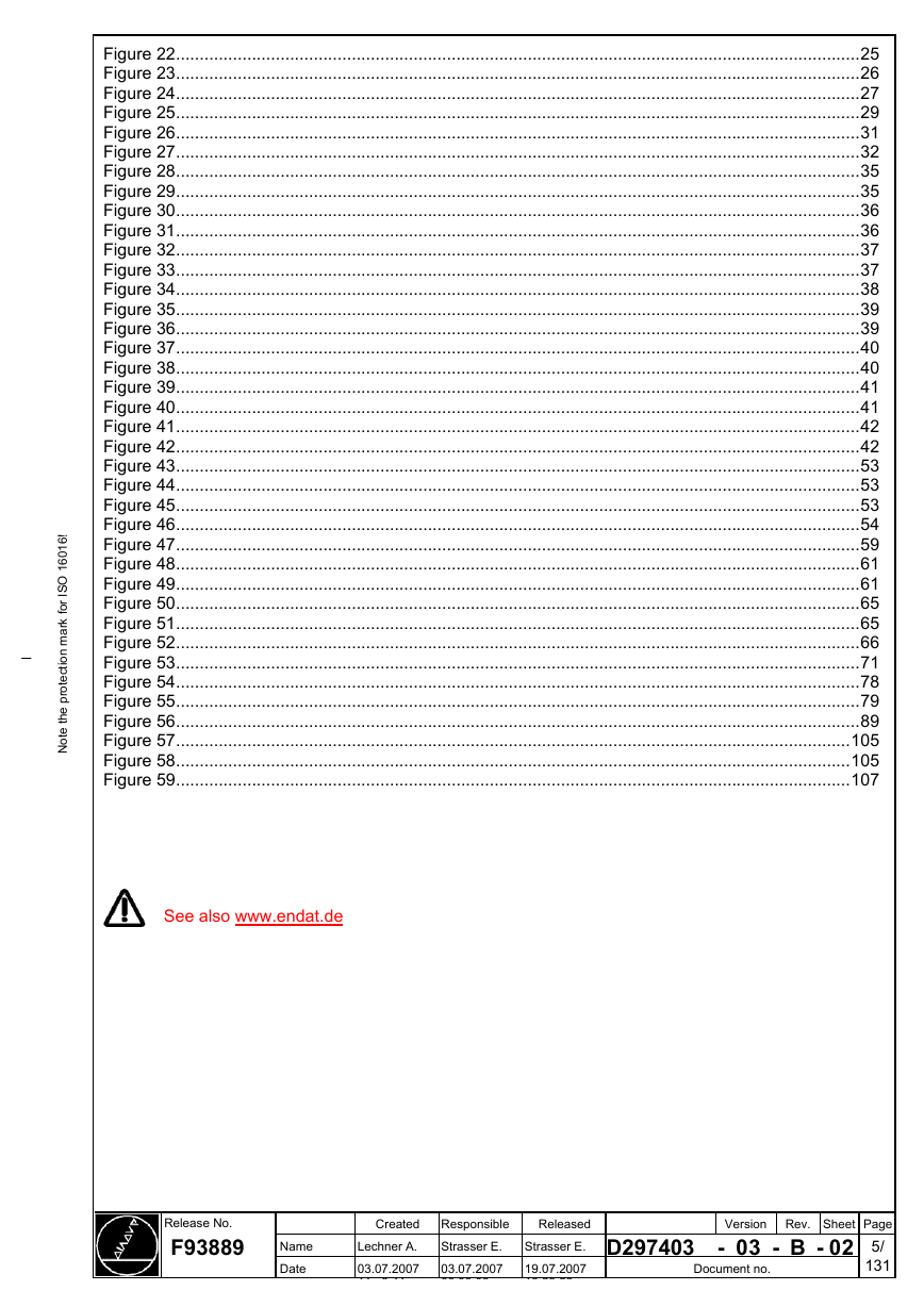
Table of Figures
Page
Figure 1....................................................................................................................................................7
Figure 2....................................................................................................................................................8
Figure 3....................................................................................................................................................8
Figure 4....................................................................................................................................................9
Figure 5..................................................................................................................................................10
Figure 6..................................................................................................................................................10
Figure 7..................................................................................................................................................11
Figure 8..................................................................................................................................................12
Figure 9..................................................................................................................................................12
Figure 10................................................................................................................................................12
Figure 11................................................................................................................................................14
Figure 12................................................................................................................................................14
Figure 13................................................................................................................................................15
Figure 14................................................................................................................................................15
Figure 15................................................................................................................................................15
Figure 16................................................................................................................................................16
Figure 17................................................................................................................................................16
Figure 18................................................................................................................................................20
Figure 19................................................................................................................................................22
Figure 20................................................................................................................................................23
Figure 21................................................................................................................................................24
Version Rev. Sheet Page
- 03 - B - 02 4/
131
Release No.
F93889
Name
Date
Document no.
Created Responsible
Strasser E.
03.07.2007
00 00 00
Lechner A.
03.07.2007
11 8 41
Released
Strasser E. D297403
19.07.2007
13 29 26
�
Figure 22................................................................................................................................................25
Figure 23................................................................................................................................................26
Figure 24................................................................................................................................................27
Figure 25................................................................................................................................................29
Figure 26................................................................................................................................................31
Figure 27................................................................................................................................................32
Figure 28................................................................................................................................................35
Figure 29................................................................................................................................................35
Figure 30................................................................................................................................................36
Figure 31................................................................................................................................................36
Figure 32................................................................................................................................................37
Figure 33................................................................................................................................................37
Figure 34................................................................................................................................................38
Figure 35................................................................................................................................................39
Figure 36................................................................................................................................................39
Figure 37................................................................................................................................................40
Figure 38................................................................................................................................................40
Figure 39................................................................................................................................................41
Figure 40................................................................................................................................................41
Figure 41................................................................................................................................................42
Figure 42................................................................................................................................................42
Figure 43................................................................................................................................................53
Figure 44................................................................................................................................................53
Figure 45................................................................................................................................................53
Figure 46................................................................................................................................................54
Figure 47................................................................................................................................................59
Figure 48................................................................................................................................................61
Figure 49................................................................................................................................................61
Figure 50................................................................................................................................................65
Figure 51................................................................................................................................................65
Figure 52................................................................................................................................................66
Figure 53................................................................................................................................................71
Figure 54................................................................................................................................................78
Figure 55................................................................................................................................................79
Figure 56................................................................................................................................................89
Figure 57..............................................................................................................................................105
Figure 58..............................................................................................................................................105
Figure 59..............................................................................................................................................107
!
6
1
0
6
1
O
S
I
r
o
f
k
r
a
m
n
o
i
t
c
e
t
o
r
p
e
h
t
e
t
o
N
See also www.endat.de
Release No.
F93889
Name
Date
Created Responsible
Strasser E.
03.07.2007
00 00 00
Lechner A.
03.07.2007
11 8 41
Released
Strasser E. D297403
19.07.2007
13 29 26
Version Rev. Sheet Page
- 03 - B - 02 5/
131
Document no.
�
1 Bidirectional Synchronous Serial Interface for Position Encoders
The interface described in this document is designed for serial data transfer of digital data between
linear, rotary or angle encoders, accelerometers and the subsequent electronics, such as
numerical controls, servo amplifiers and programmable logic controllers. It offers the following benefits:
- Permits the use of absolute encoders and incremental encoders.
- Minimizes transmission time for the position value. In applications in closed control loops this
reduces dead time and improves the control characteristics.
- Because the interface is bidirectional, the customer and the encoder manufacturer can store
parameters in the encoder and read them out on demand (simplifies commissioning).
- Supports monitoring and diagnosis of the subsequent electronics.
- With absolute position encoders, the values are always transferred in one data word. This
means that the subsequent electronics always perform the same type of evaluation regardless
of how the absolute position value is determined (Gray code, PRC code, multiple incremental
tracks with defined differences in the grating period, etc.). The absolute position value has no sign.
- Safety-relevant systems can be set up.
Compatibility with EnDat 2.1 is a subset of the command set for EnDat 2.2.
Encoders with EnDat version 2.2 can be used as replacements for encoders with
EnDat version 2.1.
If there are any deviations, they are described in the specifications.
EnDat 2.1 replacement units can also possibly have the EnDat 2.2 command set.
!
6
1
0
6
1
O
S
I
r
o
f
k
r
a
m
n
o
i
t
c
e
t
o
r
p
e
h
t
e
t
o
N
Release No.
F93889
Name
Date
Created Responsible
Strasser E.
03.07.2007
00 00 00
Lechner A.
03.07.2007
11 8 41
Released
Strasser E. D297403
19.07.2007
13 29 26
Version Rev. Sheet Page
- 03 - B - 02 6/
131
Document no.
�
2 Hardware
Bidirectional data transfer (measured values or parameters) between position encoders and
subsequent electronics is performed with transceiver components in accordance with RS-485
(differential signals), synchronous to the clock signal (CLOCK) produced by the subsequent
electronics. Additionally to the serial data transmission, the encoder can optionally provide
sinusoidal incremental signals that can be evaluated by the subsequent electronics. They have a
signal level of 1 Vpp. See the encoder’s specifications to see whether it supports additional
sinusoidal incremental signals. For special encoders that support the mode command “Encoder to
receive communication command,” see document D385768 sheet 1 for the required receiver
hardware.
!
6
1
0
6
1
O
S
I
r
o
f
k
r
a
m
n
o
i
t
c
e
t
o
r
p
e
h
t
e
t
o
N
Ra < 100 Ohm
Ca < 50 pF
∑Ia < 1 mA
Uo = 2.5 V ± 0.5 V
Figure 1
Zo = 120 Ohm
U1 ≈ Uo
RS 485 transceiver
C2 = 330 pF
The capacitors C1, C2 and C3 serve to
improve the noise immunity.
The propagation times vary between the serially transferred data and the additional incremental
signals. These differences depend on the encoder and the characteristics of the transmission
path.
A separate receiver/driver module is to be assigned to each encoder in safety-oriented
applications.
The maximum permissible clock pulse frequency depends upon the cable length and the subsequent
electronics. There are two basic versions of the subsequent electronics:
• Without delay compensation
• With delay compensation
Release No.
F93889
Name
Date
Created Responsible
Strasser E.
03.07.2007
00 00 00
Lechner A.
03.07.2007
11 8 41
Released
Strasser E. D297403
19.07.2007
13 29 26
Version Rev. Sheet Page
- 03 - B - 02 7/
131
Document no.
�
2.1 Versions of the Subsequent Electronics
2.1.1 Without Delay Compensation
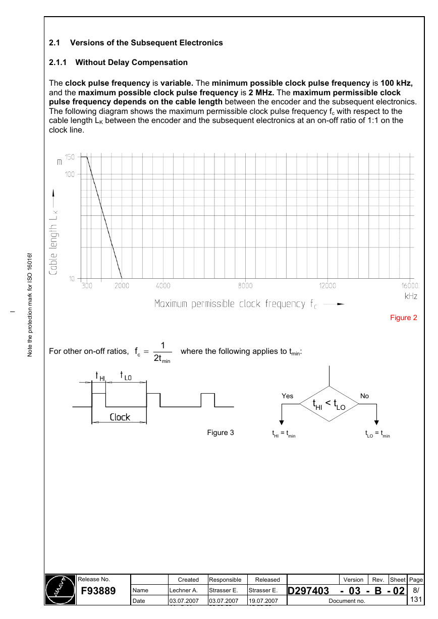
The clock pulse frequency is variable. The minimum possible clock pulse frequency is 100 kHz,
and the maximum possible clock pulse frequency is 2 MHz. The maximum permissible clock
pulse frequency depends on the cable length between the encoder and the subsequent electronics.
The following diagram shows the maximum permissible clock pulse frequency fc with respect to the
cable length LK between the encoder and the subsequent electronics at an on-off ratio of 1:1 on the
clock line.
!
6
1
0
6
1
O
S
I
r
o
f
k
r
a
m
n
o
i
t
c
e
t
o
r
p
e
h
t
e
t
o
N
For other on-off ratios,
f =
c
1
t2
min
where the following applies to tmin:
Figure 2
Yes
tHI < tLO
No
Figure 3
tHI = tmin
tLO = tmin
Release No.
F93889
Name
Date
Created Responsible
Strasser E.
03.07.2007
00 00 00
Lechner A.
03.07.2007
11 8 41
Released
Strasser E. D297403
19.07.2007
13 29 26
Version Rev. Sheet Page
- 03 - B - 02 8/
131
Document no.
�




 2023年江西萍乡中考道德与法治真题及答案.doc
 2012年重庆南川中考生物真题及答案.doc
 2013年江西师范大学地理学综合及文艺理论基础考研真题.doc
 2020年四川甘孜小升初语文真题及答案I卷.doc
 2020年注册岩土工程师专业基础考试真题及答案.doc
 2023-2024学年福建省厦门市九年级上学期数学月考试题及答案.doc
 2021-2022学年辽宁省沈阳市大东区九年级上学期语文期末试题及答案.doc
 2022-2023学年北京东城区初三第一学期物理期末试卷及答案.doc
 2018上半年江西教师资格初中地理学科知识与教学能力真题及答案.doc
 2012年河北国家公务员申论考试真题及答案-省级.doc
 2020-2021学年江苏省扬州市江都区邵樊片九年级上学期数学第一次质量检测试题及答案.doc
 2022下半年黑龙江教师资格证中学综合素质真题及答案.doc