PCI Express® Base Specification Revision 5.0
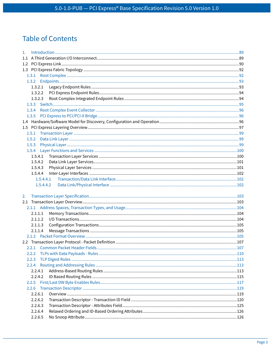
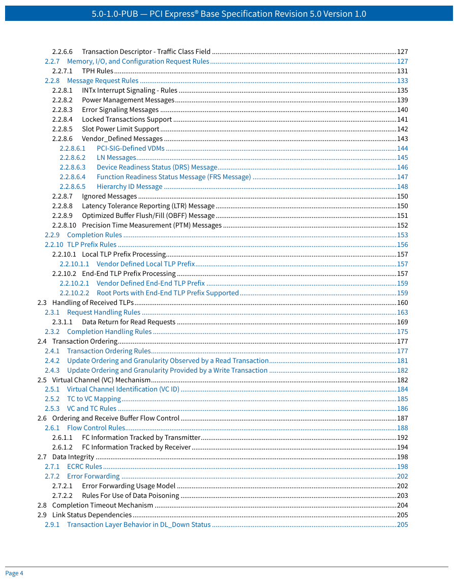
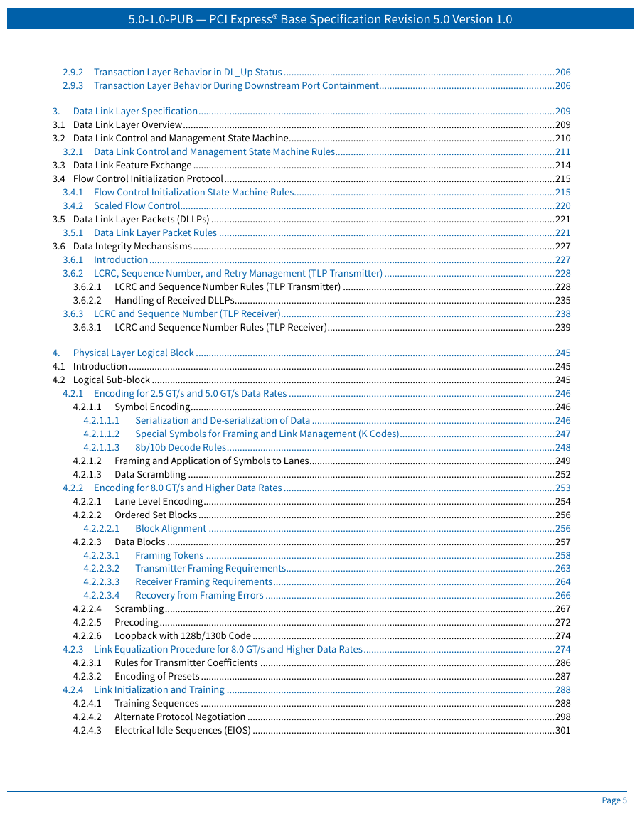
Table of Contents
Table of Figures
Table of Tables
Status of This Document
Revision History
Objective of the PCI Express® Architecture
PCI Express Architecture Specification Organization
Documentation Conventions
Terms and Acronyms
Reference Documents
Acknowledgements
1. Introduction
1.1 A Third Generation I/O Interconnect
1.2 PCI Express Link
1.3 PCI Express Fabric Topology
1.3.1 Root Complex
1.3.2 Endpoints
1.3.2.1 Legacy Endpoint Rules
1.3.2.2 PCI Express Endpoint Rules
1.3.2.3 Root Complex Integrated Endpoint Rules
1.3.3 Switch
1.3.4 Root Complex Event Collector
1.3.5 PCI Express to PCI/PCI-X Bridge
1.4 Hardware/Software Model for Discovery, Configuration and Operation
1.5 PCI Express Layering Overview
1.5.1 Transaction Layer
1.5.2 Data Link Layer
1.5.3 Physical Layer
1.5.4 Layer Functions and Services
1.5.4.1 Transaction Layer Services
1.5.4.2 Data Link Layer Services
1.5.4.3 Physical Layer Services
1.5.4.4 Inter-Layer Interfaces
1.5.4.4.1 Transaction/Data Link Interface
1.5.4.4.2 Data Link/Physical Interface
2. Transaction Layer Specification
2.1 Transaction Layer Overview
2.1.1 Address Spaces, Transaction Types, and Usage
2.1.1.1 Memory Transactions
2.1.1.2 I/O Transactions
2.1.1.3 Configuration Transactions
2.1.1.4 Message Transactions
2.1.2 Packet Format Overview
2.2 Transaction Layer Protocol - Packet Definition
2.2.1 Common Packet Header Fields
2.2.2 TLPs with Data Payloads - Rules
2.2.3 TLP Digest Rules
2.2.4 Routing and Addressing Rules
2.2.4.1 Address-Based Routing Rules
2.2.4.2 ID Based Routing Rules
2.2.5 First/Last DW Byte Enables Rules
2.2.6 Transaction Descriptor
2.2.6.1 Overview
2.2.6.2 Transaction Descriptor - Transaction ID Field
2.2.6.3 Transaction Descriptor - Attributes Field
2.2.6.4 Relaxed Ordering and ID-Based Ordering Attributes
2.2.6.5 No Snoop Attribute
2.2.6.6 Transaction Descriptor - Traffic Class Field
2.2.7 Memory, I/O, and Configuration Request Rules
2.2.7.1 TPH Rules
2.2.8 Message Request Rules
2.2.8.1 INTx Interrupt Signaling - Rules
2.2.8.2 Power Management Messages
2.2.8.3 Error Signaling Messages
2.2.8.4 Locked Transactions Support
2.2.8.5 Slot Power Limit Support
2.2.8.6 Vendor_Defined Messages
2.2.8.6.1 PCI-SIG-Defined VDMs
2.2.8.6.2 LN Messages
2.2.8.6.3 Device Readiness Status (DRS) Message
2.2.8.6.4 Function Readiness Status Message (FRS Message)
2.2.8.6.5 Hierarchy ID Message
2.2.8.7 Ignored Messages
2.2.8.8 Latency Tolerance Reporting (LTR) Message
2.2.8.9 Optimized Buffer Flush/Fill (OBFF) Message
2.2.8.10 Precision Time Measurement (PTM) Messages
2.2.9 Completion Rules
2.2.10 TLP Prefix Rules
2.2.10.1 Local TLP Prefix Processing
2.2.10.1.1 Vendor Defined Local TLP Prefix
2.2.10.2 End-End TLP Prefix Processing
2.2.10.2.1 Vendor Defined End-End TLP Prefix
2.2.10.2.2 Root Ports with End-End TLP Prefix Supported
2.3 Handling of Received TLPs
2.3.1 Request Handling Rules
2.3.1.1 Data Return for Read Requests
2.3.2 Completion Handling Rules
2.4 Transaction Ordering
2.4.1 Transaction Ordering Rules
2.4.2 Update Ordering and Granularity Observed by a Read Transaction
2.4.3 Update Ordering and Granularity Provided by a Write Transaction
2.5 Virtual Channel (VC) Mechanism
2.5.1 Virtual Channel Identification (VC ID)
2.5.2 TC to VC Mapping
2.5.3 VC and TC Rules
2.6 Ordering and Receive Buffer Flow Control
2.6.1 Flow Control Rules
2.6.1.1 FC Information Tracked by Transmitter
2.6.1.2 FC Information Tracked by Receiver
2.7 Data Integrity
2.7.1 ECRC Rules
2.7.2 Error Forwarding
2.7.2.1 Error Forwarding Usage Model
2.7.2.2 Rules For Use of Data Poisoning
2.8 Completion Timeout Mechanism
2.9 Link Status Dependencies
2.9.1 Transaction Layer Behavior in DL_Down Status
2.9.2 Transaction Layer Behavior in DL_Up Status
2.9.3 Transaction Layer Behavior During Downstream Port Containment
3. Data Link Layer Specification
3.1 Data Link Layer Overview
3.2 Data Link Control and Management State Machine
3.2.1 Data Link Control and Management State Machine Rules
3.3 Data Link Feature Exchange
3.4 Flow Control Initialization Protocol
3.4.1 Flow Control Initialization State Machine Rules
3.4.2 Scaled Flow Control
3.5 Data Link Layer Packets (DLLPs)
3.5.1 Data Link Layer Packet Rules
3.6 Data Integrity Mechansisms
3.6.1 Introduction
3.6.2 LCRC, Sequence Number, and Retry Management (TLP Transmitter)
3.6.2.1 LCRC and Sequence Number Rules (TLP Transmitter)
3.6.2.2 Handling of Received DLLPs
3.6.3 LCRC and Sequence Number (TLP Receiver)
3.6.3.1 LCRC and Sequence Number Rules (TLP Receiver)
4. Physical Layer Logical Block
4.1 Introduction
4.2 Logical Sub-block
4.2.1 Encoding for 2.5 GT/s and 5.0 GT/s Data Rates
4.2.1.1 Symbol Encoding
4.2.1.1.1 Serialization and De-serialization of Data
4.2.1.1.2 Special Symbols for Framing and Link Management (K Codes)
4.2.1.1.3 8b/10b Decode Rules
4.2.1.2 Framing and Application of Symbols to Lanes
4.2.1.3 Data Scrambling
4.2.2 Encoding for 8.0 GT/s and Higher Data Rates
4.2.2.1 Lane Level Encoding
4.2.2.2 Ordered Set Blocks
4.2.2.2.1 Block Alignment
4.2.2.3 Data Blocks
4.2.2.3.1 Framing Tokens
4.2.2.3.2 Transmitter Framing Requirements
4.2.2.3.3 Receiver Framing Requirements
4.2.2.3.4 Recovery from Framing Errors
4.2.2.4 Scrambling
4.2.2.5 Precoding
4.2.2.6 Loopback with 128b/130b Code
4.2.3 Link Equalization Procedure for 8.0 GT/s and Higher Data Rates
4.2.3.1 Rules for Transmitter Coefficients
4.2.3.2 Encoding of Presets
4.2.4 Link Initialization and Training
4.2.4.1 Training Sequences
4.2.4.2 Alternate Protocol Negotiation
4.2.4.3 Electrical Idle Sequences (EIOS)
4.2.4.4 Inferring Electrical Idle
4.2.4.5 Lane Polarity Inversion
4.2.4.6 Fast Training Sequence (FTS)
4.2.4.7 Start of Data Stream Ordered Set (SDS Ordered Set)
4.2.4.8 Link Error Recovery
4.2.4.9 Reset
4.2.4.9.1 Fundamental Reset
4.2.4.9.2 Hot Reset
4.2.4.10 Link Data Rate Negotiation
4.2.4.11 Link Width and Lane Sequence Negotiation
4.2.4.11.1 Required and Optional Port Behavior
4.2.4.12 Lane-to-Lane De-skew
4.2.4.13 Lane vs. Link Training
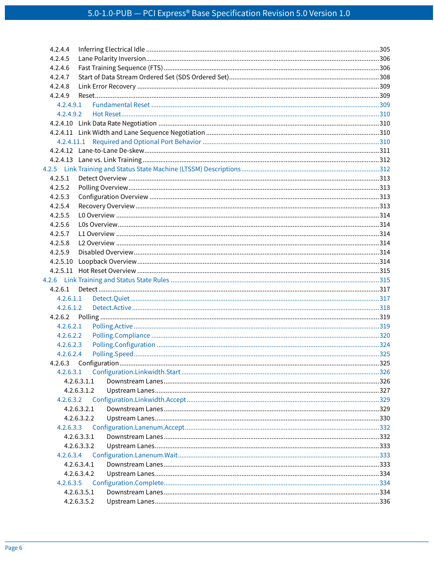
4.2.5 Link Training and Status State Machine (LTSSM) Descriptions
4.2.5.1 Detect Overview
4.2.5.2 Polling Overview
4.2.5.3 Configuration Overview
4.2.5.4 Recovery Overview
4.2.5.5 L0 Overview
4.2.5.6 L0s Overview
4.2.5.7 L1 Overview
4.2.5.8 L2 Overview
4.2.5.9 Disabled Overview
4.2.5.10 Loopback Overview
4.2.5.11 Hot Reset Overview
4.2.6 Link Training and Status State Rules
4.2.6.1 Detect
4.2.6.1.1 Detect.Quiet
4.2.6.1.2 Detect.Active
4.2.6.2 Polling
4.2.6.2.1 Polling.Active
4.2.6.2.2 Polling.Compliance
4.2.6.2.3 Polling.Configuration
4.2.6.2.4 Polling.Speed
4.2.6.3 Configuration
4.2.6.3.1 Configuration.Linkwidth.Start
4.2.6.3.1.1 Downstream Lanes
4.2.6.3.1.2 Upstream Lanes
4.2.6.3.2 Configuration.Linkwidth.Accept
4.2.6.3.2.1 Downstream Lanes
4.2.6.3.2.2 Upstream Lanes
4.2.6.3.3 Configuration.Lanenum.Accept
4.2.6.3.3.1 Downstream Lanes
4.2.6.3.3.2 Upstream Lanes
4.2.6.3.4 Configuration.Lanenum.Wait
4.2.6.3.4.1 Downstream Lanes
4.2.6.3.4.2 Upstream Lanes
4.2.6.3.5 Configuration.Complete
4.2.6.3.5.1 Downstream Lanes
4.2.6.3.5.2 Upstream Lanes
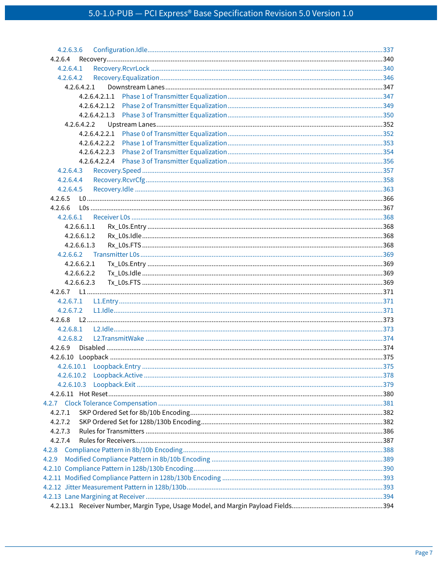
4.2.6.3.6 Configuration.Idle
4.2.6.4 Recovery
4.2.6.4.1 Recovery.RcvrLock
4.2.6.4.2 Recovery.Equalization
4.2.6.4.2.1 Downstream Lanes
4.2.6.4.2.1.1 Phase 1 of Transmitter Equalization
4.2.6.4.2.1.2 Phase 2 of Transmitter Equalization
4.2.6.4.2.1.3 Phase 3 of Transmitter Equalization
4.2.6.4.2.2 Upstream Lanes
4.2.6.4.2.2.1 Phase 0 of Transmitter Equalization
4.2.6.4.2.2.2 Phase 1 of Transmitter Equalization
4.2.6.4.2.2.3 Phase 2 of Transmitter Equalization
4.2.6.4.2.2.4 Phase 3 of Transmitter Equalization
4.2.6.4.3 Recovery.Speed
4.2.6.4.4 Recovery.RcvrCfg
4.2.6.4.5 Recovery.Idle
4.2.6.5 L0
4.2.6.6 L0s
4.2.6.6.1 Receiver L0s
4.2.6.6.1.1 Rx_L0s.Entry
4.2.6.6.1.2 Rx_L0s.Idle
4.2.6.6.1.3 Rx_L0s.FTS
4.2.6.6.2 Transmitter L0s
4.2.6.6.2.1 Tx_L0s.Entry
4.2.6.6.2.2 Tx_L0s.Idle
4.2.6.6.2.3 Tx_L0s.FTS
4.2.6.7 L1
4.2.6.7.1 L1.Entry
4.2.6.7.2 L1.Idle
4.2.6.8 L2
4.2.6.8.1 L2.Idle
4.2.6.8.2 L2.TransmitWake
4.2.6.9 Disabled
4.2.6.10 Loopback
4.2.6.10.1 Loopback.Entry
4.2.6.10.2 Loopback.Active
4.2.6.10.3 Loopback.Exit
4.2.6.11 Hot Reset
4.2.7 Clock Tolerance Compensation
4.2.7.1 SKP Ordered Set for 8b/10b Encoding
4.2.7.2 SKP Ordered Set for 128b/130b Encoding
4.2.7.3 Rules for Transmitters
4.2.7.4 Rules for Receivers
4.2.8 Compliance Pattern in 8b/10b Encoding
4.2.9 Modified Compliance Pattern in 8b/10b Encoding
4.2.10 Compliance Pattern in 128b/130b Encoding
4.2.11 Modified Compliance Pattern in 128b/130b Encoding
4.2.12 Jitter Measurement Pattern in 128b/130b
4.2.13 Lane Margining at Receiver
4.2.13.1 Receiver Number, Margin Type, Usage Model, and Margin Payload Fields
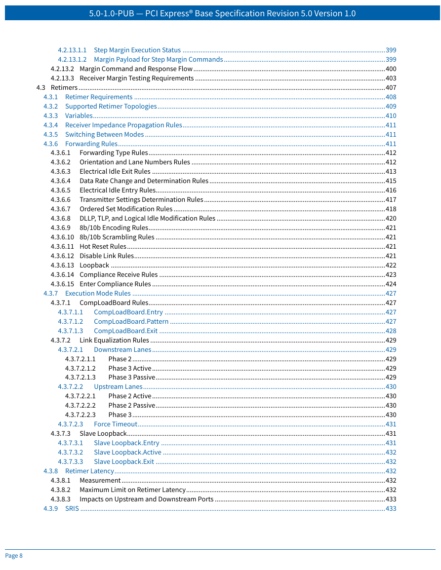
4.2.13.1.1 Step Margin Execution Status
4.2.13.1.2 Margin Payload for Step Margin Commands
4.2.13.2 Margin Command and Response Flow
4.2.13.3 Receiver Margin Testing Requirements
4.3 Retimers
4.3.1 Retimer Requirements
4.3.2 Supported Retimer Topologies
4.3.3 Variables
4.3.4 Receiver Impedance Propagation Rules
4.3.5 Switching Between Modes
4.3.6 Forwarding Rules
4.3.6.1 Forwarding Type Rules
4.3.6.2 Orientation and Lane Numbers Rules
4.3.6.3 Electrical Idle Exit Rules
4.3.6.4 Data Rate Change and Determination Rules
4.3.6.5 Electrical Idle Entry Rules
4.3.6.6 Transmitter Settings Determination Rules
4.3.6.7 Ordered Set Modification Rules
4.3.6.8 DLLP, TLP, and Logical Idle Modification Rules
4.3.6.9 8b/10b Encoding Rules
4.3.6.10 8b/10b Scrambling Rules
4.3.6.11 Hot Reset Rules
4.3.6.12 Disable Link Rules
4.3.6.13 Loopback
4.3.6.14 Compliance Receive Rules
4.3.6.15 Enter Compliance Rules
4.3.7 Execution Mode Rules
4.3.7.1 CompLoadBoard Rules
4.3.7.1.1 CompLoadBoard.Entry
4.3.7.1.2 CompLoadBoard.Pattern
4.3.7.1.3 CompLoadBoard.Exit
4.3.7.2 Link Equalization Rules
4.3.7.2.1 Downstream Lanes
4.3.7.2.1.1 Phase 2
4.3.7.2.1.2 Phase 3 Active
4.3.7.2.1.3 Phase 3 Passive
4.3.7.2.2 Upstream Lanes
4.3.7.2.2.1 Phase 2 Active
4.3.7.2.2.2 Phase 2 Passive
4.3.7.2.2.3 Phase 3
4.3.7.2.3 Force Timeout
4.3.7.3 Slave Loopback
4.3.7.3.1 Slave Loopback.Entry
4.3.7.3.2 Slave Loopback.Active
4.3.7.3.3 Slave Loopback.Exit
4.3.8 Retimer Latency
4.3.8.1 Measurement
4.3.8.2 Maximum Limit on Retimer Latency
4.3.8.3 Impacts on Upstream and Downstream Ports
4.3.9 SRIS
4.3.10 L1 PM Substates Support
4.3.11 Retimer Configuration Parameters
4.3.11.1 Global Parameters
4.3.11.2 Per Physical Pseudo Port Parameters
4.3.12 In Band Register Access
5. Power Management
5.1 Overview
5.2 Link State Power Management
5.3 PCI-PM Software Compatible Mechanisms
5.3.1 Device Power Management States (D-States) of a Function
5.3.1.1 D0 State
5.3.1.2 D1 State
5.3.1.3 D2 State
5.3.1.4 D3 State
5.3.1.4.1 D3Hot State
5.3.1.4.2 D3Cold State
5.3.2 PM Software Control of the Link Power Management State
5.3.2.1 Entry into the L1 State
5.3.2.2 Exit from L1 State
5.3.2.3 Entry into the L2/L3 Ready State
5.3.3 Power Management Event Mechanisms
5.3.3.1 Motivation
5.3.3.2 Link Wakeup
5.3.3.2.1 PME Synchronization
5.3.3.3 PM_PME Messages
5.3.3.3.1 PM_PME “Backpressure” Deadlock Avoidance
5.3.3.4 PME Rules
5.3.3.5 PM_PME Delivery State Machine
5.4 Native PCI Express Power Management Mechanisms
5.4.1 Active State Power Management (ASPM)
5.4.1.1 L0s ASPM State
5.4.1.1.1 Entry into the L0s State
5.4.1.1.2 Exit from the L0s State
5.4.1.2 L1 ASPM State
5.4.1.2.1 ASPM Entry into the L1 State
5.4.1.2.2 Exit from the L1 State
5.4.1.3 ASPM Configuration
5.4.1.3.1 Software Flow for Enabling or Disabling ASPM
5.5 L1 PM Substates
5.5.1 Entry conditions for L1 PM Substates and L1.0 Requirements
5.5.2 L1.1 Requirements
5.5.2.1 Exit from L1.1
5.5.3 L1.2 Requirements
5.5.3.1 L1.2.Entry
5.5.3.2 L1.2.Idle
5.5.3.3 L1.2.Exit
5.5.3.3.1 Exit from L1.2
5.5.4 L1 PM Substates Configuration
5.5.5 L1 PM Substates Timing Parameters
5.5.6 Link Activation
5.6 Auxiliary Power Support
5.7 Power Management System Messages and DLLPs
5.8 PCI Function Power State Transitions
5.9 State Transition Recovery Time Requirements
5.10 PCI Bridges and Power Management
5.10.1 Switches and PCI Express to PCI Bridges
5.11 Power Management Events
6. System Architecture
6.1 Interrupt and PME Support
6.1.1 Rationale for PCI Express Interrupt Model
6.1.2 PCI-compatible INTx Emulation
6.1.3 INTx Emulation Software Model
6.1.4 MSI and MSI-X Operation
6.1.4.1 MSI Configuration
6.1.4.2 MSI-X Configuration
6.1.4.3 Enabling Operation
6.1.4.4 Sending Messages
6.1.4.5 Per-vector Masking and Function Masking
6.1.4.6 Hardware/Software Synchronization
6.1.4.7 Message Transaction Reception and Ordering Requirements
6.1.5 PME Support
6.1.6 Native PME Software Model
6.1.7 Legacy PME Software Model
6.1.8 Operating System Power Management Notification
6.1.9 PME Routing Between PCI Express and PCI Hierarchies
6.2 Error Signaling and Logging
6.2.1 Scope
6.2.2 Error Classification
6.2.2.1 Correctable Errors
6.2.2.2 Uncorrectable Errors
6.2.2.2.1 Fatal Errors
6.2.2.2.2 Non-Fatal Errors
6.2.3 Error Signaling
6.2.3.1 Completion Status
6.2.3.2 Error Messages
6.2.3.2.1 Uncorrectable Error Severity Programming (Advanced Error Reporting)
6.2.3.2.2 Masking Individual Errors
6.2.3.2.3 Error Pollution
6.2.3.2.4 Advisory Non-Fatal Error Cases
6.2.3.2.4.1 Completer Sending a Completion with UR/CA Status
6.2.3.2.4.2 Intermediate Receiver
6.2.3.2.4.3 Ultimate PCI Express Receiver of a Poisoned TLP
6.2.3.2.4.4 Requester with Completion Timeout
6.2.3.2.4.5 Receiver of an Unexpected Completion
6.2.3.2.5 Requester Receiving a Completion with UR/CA Status
6.2.3.3 Error Forwarding (Data Poisoning)
6.2.3.4 Optional Error Checking
6.2.4 Error Logging
6.2.4.1 Root Complex Considerations (Advanced Error Reporting)
6.2.4.1.1 Error Source Identification
6.2.4.1.2 Interrupt Generation
6.2.4.2 Multiple Error Handling (Advanced Error Reporting Capability)
6.2.4.3 Advisory Non-Fatal Error Logging
6.2.4.4 TLP Prefix Logging
6.2.5 Sequence of Device Error Signaling and Logging Operations
6.2.6 Error Message Controls
6.2.7 Error Listing and Rules
6.2.7.1 Conventional PCI Mapping
6.2.8 Virtual PCI Bridge Error Handling
6.2.8.1 Error Message Forwarding and PCI Mapping for Bridge - Rules
6.2.9 Internal Errors
6.2.10 Downstream Port Containment (DPC)
6.2.10.1 DPC Interrupts
6.2.10.2 DPC ERR_COR Signaling
6.2.10.3 Root Port Programmed I/O (RP PIO) Error Controls
6.2.10.4 Software Triggering of DPC
6.2.10.5 DL_Active ERR_COR Signaling
6.3 Virtual Channel Support
6.3.1 Introduction and Scope
6.3.2 TC/VC Mapping and Example Usage
6.3.3 VC Arbitration
6.3.3.1 Traffic Flow and Switch Arbitration Model
6.3.3.2 VC Arbitration - Arbitration Between VCs
6.3.3.2.1 Strict Priority Arbitration Model
6.3.3.2.2 Round Robin Arbitration Model
6.3.3.3 Port Arbitration - Arbitration Within VC
6.3.3.4 Multi-Function Devices and Function Arbitration
6.3.4 Isochronous Support
6.3.4.1 Rules for Software Configuration
6.3.4.2 Rules for Requesters
6.3.4.3 Rules for Completers
6.3.4.4 Rules for Switches and Root Complexes
6.3.4.5 Rules for Multi-Function Devices
6.4 Device Synchronization
6.5 Locked Transactions
6.5.1 Introduction
6.5.2 Initiation and Propagation of Locked Transactions - Rules
6.5.3 Switches and Lock - Rules
6.5.4 PCI Express/PCI Bridges and Lock - Rules
6.5.5 Root Complex and Lock - Rules
6.5.6 Legacy Endpoints
6.5.7 PCI Express Endpoints
6.6 PCI Express Reset - Rules
6.6.1 Conventional Reset
6.6.2 Function Level Reset (FLR)
6.7 PCI Express Native Hot-Plug
6.7.1 Elements of Hot-Plug
6.7.1.1 Indicators
6.7.1.1.1 Attention Indicator
6.7.1.1.2 Power Indicator
6.7.1.2 Manually-operated Retention Latch (MRL)
6.7.1.3 MRL Sensor
6.7.1.4 Electromechanical Interlock
6.7.1.5 Attention Button
6.7.1.6 Software User Interface
6.7.1.7 Slot Numbering
6.7.1.8 Power Controller
6.7.2 Registers Grouped by Hot-Plug Element Association
6.7.2.1 Attention Button Registers
6.7.2.2 Attention Indicator Registers
6.7.2.3 Power Indicator Registers
6.7.2.4 Power Controller Registers
6.7.2.5 Presence Detect Registers
6.7.2.6 MRL Sensor Registers
6.7.2.7 Electromechanical Interlock Registers
6.7.2.8 Command Completed Registers
6.7.2.9 Port Capabilities and Slot Information Registers
6.7.2.10 Hot-Plug Interrupt Control Register
6.7.3 PCI Express Hot-Plug Events
6.7.3.1 Slot Events
6.7.3.2 Command Completed Events
6.7.3.3 Data Link Layer State Changed Events
6.7.3.4 Software Notification of Hot-Plug Events
6.7.4 System Firmware Intermediary (SFI) Support
6.7.4.1 SFI ERR_COR Event Signaling
6.7.4.2 SFI Downstream Port Filtering (DPF)
6.7.4.3 SFI CAM
6.7.4.4 SFI Interactions with Readiness Notifications
6.7.4.5 SFI Suppression of Hot-Plug Surprise Functionality
6.7.5 Firmware Support for Hot-Plug
6.7.6 Async Removal
6.8 Power Budgeting Capability
6.8.1 System Power Budgeting Process Recommendations
6.9 Slot Power Limit Control
6.10 Root Complex Topology Discovery
6.11 Link Speed Management
6.12 Access Control Services (ACS)
6.12.1 ACS Component Capability Requirements
6.12.1.1 ACS Downstream Ports
6.12.1.2 ACS Functions in SR-IOV Capable and Multi-Function Devices
6.12.1.3 Functions in Single-Function Devices
6.12.2 Interoperability
6.12.3 ACS Peer-to-Peer Control Interactions
6.12.4 ACS Enhanced Capability
6.12.5 ACS Violation Error Handling
6.12.6 ACS Redirection Impacts on Ordering Rules
6.12.6.1 Completions Passing Posted Requests
6.12.6.2 Requests Passing Posted Requests
6.13 Alternative Routing-ID Interpretation (ARI)
6.14 Multicast Operations
6.14.1 Multicast TLP Processing
6.14.2 Multicast Ordering
6.14.3 Multicast Capability Structure Field Updates
6.14.4 MC Blocked TLP Processing
6.14.5 MC_Overlay Mechanism
6.15 Atomic Operations (AtomicOps)
6.15.1 AtomicOp Use Models and Benefits
6.15.2 AtomicOp Transaction Protocol Summary
6.15.3 Root Complex Support for AtomicOps
6.15.3.1 Root Ports with AtomicOp Completer Capabilities
6.15.3.2 Root Ports with AtomicOp Routing Capability
6.15.3.3 RCs with AtomicOp Requester Capabilities
6.15.4 Switch Support for AtomicOps
6.16 Dynamic Power Allocation (DPA) Capability
6.16.1 DPA Capability with Multi-Function Devices
6.17 TLP Processing Hints (TPH)
6.17.1 Processing Hints
6.17.2 Steering Tags
6.17.3 ST Modes of Operation
6.17.4 TPH Capability
6.18 Latency Tolerance Reporting (LTR) Mechanism
6.19 Optimized Buffer Flush/Fill (OBFF) Mechanism
6.20 PASID TLP Prefix
6.20.1 Managing PASID TLP Prefix Usage
6.20.2 PASID TLP Layout
6.20.2.1 PASID field
6.20.2.2 Execute Requested
6.20.2.3 Privileged Mode Requested
6.21 Lightweight Notification (LN) Protocol
6.21.1 LN Protocol Operation
6.21.2 LN Registration Management
6.21.3 LN Ordering Considerations
6.21.4 LN Software Configuration
6.21.5 LN Protocol Summary
6.22 Precision Time Measurement (PTM) Mechanism
6.22.1 Introduction
6.22.2 PTM Link Protocol
6.22.3 Configuration and Operational Requirements
6.22.3.1 PTM Requester Role
6.22.3.2 PTM Responder Role
6.22.3.3 PTM Time Source Role - Rules Specific to Switches
6.23 Readiness Notifications (RN)
6.23.1 Device Readiness Status (DRS)
6.23.2 Function Readiness Status (FRS)
6.23.3 FRS Queuing
6.24 Enhanced Allocation
6.25 Emergency Power Reduction State
6.26 Hierarchy ID Message
6.27 Flattening Portal Bridge (FPB)
6.27.1 Introduction
6.27.2 Hardware and Software Requirements
6.28 Vital Product Data (VPD)
6.28.1 VPD Format
6.28.2 VPD Definitions
6.28.2.1 VPD Large and Small Resource Data Tags
6.28.2.2 Read-Only Fields
6.28.2.3 Read/Write Fields
6.28.2.4 VPD Example
6.29 Native PCIe Enclosure Management
6.30 Conventional PCI Advanced Features Operation
7. Software Initialization and Configuration
7.1 Configuration Topology
7.2 PCI Express Configuration Mechanisms
7.2.1 PCI-compatible Configuration Mechanism
7.2.2 PCI Express Enhanced Configuration Access Mechanism (ECAM)
7.2.2.1 Host Bridge Requirements
7.2.2.2 PCI Express Device Requirements
7.2.3 Root Complex Register Block (RCRB)
7.3 Configuration Transaction Rules
7.3.1 Device Number
7.3.2 Configuration Transaction Addressing
7.3.3 Configuration Request Routing Rules
7.3.4 PCI Special Cycles
7.4 Configuration Register Types
7.5 PCI and PCIe Capabilities Required by the Base Spec for all Ports
7.5.1 PCI-Compatible Configuration Registers
7.5.1.1 Type 0/1 Common Configuration Space
7.5.1.1.1 Vendor ID Register (Offset 00h)
7.5.1.1.2 Device ID Register (Offset 02h)
7.5.1.1.3 Command Register (Offset 04h)
7.5.1.1.4 Status Register (Offset 06h)
7.5.1.1.5 Revision ID Register (Offset 08h)
7.5.1.1.6 Class Code Register (Offset 09h)
7.5.1.1.7 Cache Line Size Register (Offset 0Ch)
7.5.1.1.8 Latency Timer Register (Offset 0Dh)
7.5.1.1.9 Header Type Register (Offset 0Eh)
7.5.1.1.10 BIST Register (Offset 0Fh)
7.5.1.1.11 Capabilities Pointer (Offset 34h)
7.5.1.1.12 Interrupt Line Register (Offset 3Ch)
7.5.1.1.13 Interrupt Pin Register (Offset 3Dh)
7.5.1.1.14 Error Registers
7.5.1.2 Type 0 Configuration Space Header
7.5.1.2.1 Base Address Registers (Offset 10h - 24h)
7.5.1.2.2 Cardbus CIS Pointer Register (Offset 28h)
7.5.1.2.3 Subsystem Vendor ID Register/Subsystem ID Register (Offset 2Ch/2Eh)
7.5.1.2.4 Expansion ROM Base Address Register (Offset 30h)
7.5.1.2.5 Min_Gnt Register/Max_Lat Register (Offset 3Eh/3Fh)
7.5.1.3 Type 1 Configuration Space Header
7.5.1.3.1 Type 1 Base Address Registers (Offset 10h-14h)
7.5.1.3.2 Primary Bus Number Register (Offset 18h)
7.5.1.3.3 Secondary Bus Number Register (Offset 19h)
7.5.1.3.4 Subordinate Bus Number Register (Offset 1Ah)
7.5.1.3.5 Secondary Latency Timer (Offset 1Bh)
7.5.1.3.6 I/O Base/I/O Limit Registers(Offset 1Ch/1Dh)
7.5.1.3.7 Secondary Status Register (Offset 1Eh)
7.5.1.3.8 Memory Base Register/Memory Limit Register(Offset 20h/22h)
7.5.1.3.9 Prefetchable Memory Base/Prefetchable Memory Limit Registers (Offset 24h/26h)
7.5.1.3.10 Prefetchable Base Upper 32 Bits/Prefetchable Limit Upper 32 Bits Registers (Offset 28h/2Ch)
7.5.1.3.11 I/O Base Upper 16 Bits/I/O Limit Upper 16 Bits Registers (Offset 30h/32h)
7.5.1.3.12 Expansion ROM Base Address Register (Offset 38h)
7.5.1.3.13 Bridge Control Register (Offset 3Eh)
7.5.2 PCI Power Management Capability Structure
7.5.2.1 Power Management Capabilities Register (Offset 00h)
7.5.2.2 Power Management Control/Status Register (Offset 04h)
7.5.2.3 Data (Offset 07h)
7.5.3 PCI Express Capability Structure
7.5.3.1 PCI Express Capability List Register (Offset 00h)
7.5.3.2 PCI Express Capabilities Register (Offset 02h)
7.5.3.3 Device Capabilities Register (Offset 04h)
7.5.3.4 Device Control Register (Offset 08h)
7.5.3.5 Device Status Register (Offset 0Ah)
7.5.3.6 Link Capabilities Register (Offset 0Ch)
7.5.3.7 Link Control Register (Offset 10h)
7.5.3.8 Link Status Register (Offset 12h)
7.5.3.9 Slot Capabilities Register (Offset 14h)
7.5.3.10 Slot Control Register (Offset 18h)
7.5.3.11 Slot Status Register (Offset 1Ah)
7.5.3.12 Root Control Register (Offset 1Ch)
7.5.3.13 Root Capabilities Register (Offset 1Eh)
7.5.3.14 Root Status Register (Offset 20h)
7.5.3.15 Device Capabilities 2 Register (Offset 24h)
7.5.3.16 Device Control 2 Register (Offset 28h)
7.5.3.17 Device Status 2 Register (Offset 2Ah)
7.5.3.18 Link Capabilities 2 Register (Offset 2Ch)
7.5.3.19 Link Control 2 Register (Offset 30h)
7.5.3.20 Link Status 2 Register (Offset 32h)
7.5.3.21 Slot Capabilities 2 Register (Offset 34h)
7.5.3.22 Slot Control 2 Register (Offset 38h)
7.5.3.23 Slot Status 2 Register (Offset 3Ah)
7.6 PCI Express Extended Capabilities
7.6.1 Extended Capabilities in Configuration Space
7.6.2 Extended Capabilities in the Root Complex Register Block
7.6.3 PCI Express Extended Capability Header
7.7 PCI and PCIe Capabilities Required by the Base Spec in Some Situations
7.7.1 MSI Capability Structures
7.7.1.1 MSI Capability Header (Offset 00h)
7.7.1.2 Message Control Register for MSI (Offset 02h)
7.7.1.3 Message Address Register for MSI (Offset 04h)
7.7.1.4 Message Upper Address Register for MSI (Offset 08h)
7.7.1.5 Message Data Register for MSI (Offset 08h or 0Ch)
7.7.1.6 Extended Message Data Register for MSI (Optional)
7.7.1.7 Mask Bits Register for MSI (Offset 0Ch or 10h
7.7.1.8 Pending Bits Register for MSI (Offset 10h or 14h)
7.7.2 MSI-X Capability and Table Structure
7.7.2.1 MSI-X Capability Header (Offset 00h)
7.7.2.2 Message Control Register for MSI-X (Offset 02h)
7.7.2.3 Table Offset/Table BIR Register for MSI-X (Offset 04h)
7.7.2.4 PBA Offset/PBA BIR Register for MSI-X (Offset 08h)
7.7.2.5 Message Address Register for MSI-X Table Entries
7.7.2.6 Message Upper Address Register for MSI-X Table Entries
7.7.2.7 Message Data Register for MSI-X Table Entries
7.7.2.8 Vector Control Register for MSI-X Table Entries
7.7.2.9 Pending Bits Register for MSI-X PBA Entries
7.7.3 Secondary PCI Express Extended Capability
7.7.3.1 Secondary PCI Express Extended Capability Header (Offset 00h)
7.7.3.2 Link Control 3 Register (Offset 04h)
7.7.3.3 Lane Error Status Register (Offset 08h)
7.7.3.4 Lane Equalization Control Register (Offset 0Ch)
7.7.4 Data Link Feature Extended Capability
7.7.4.1 Data Link Feature Extended Capability Header (Offset 00h)
7.7.4.2 Data Link Feature Capabilities Register (Offset 04h)
7.7.4.3 Data Link Feature Status Register (Offset 08h)
7.7.5 Physical Layer 16.0 GT/s Extended Capability
7.7.5.1 Physical Layer 16.0 GT/s Extended Capability Header (Offset 00h)
7.7.5.2 16.0 GT/s Capabilities Register (Offset 04h)
7.7.5.3 16.0 GT/s Control Register (Offset 08h)
7.7.5.4 16.0 GT/s Status Register (Offset 0Ch)
7.7.5.5 16.0 GT/s Local Data Parity Mismatch Status Register (Offset 10h)
7.7.5.6 16.0 GT/s First Retimer Data Parity Mismatch Status Register (Offset 14h)
7.7.5.7 16.0 GT/s Second Retimer Data Parity Mismatch Status Register (Offset 18h)
7.7.5.8 Physical Layer 16.0 GT/s Reserved (Offset 1Ch)
7.7.5.9 16.0 GT/s Lane Equalization Control Register (Offsets 20h to 3Ch)
7.7.6 Physical Layer 32.0 GT/s Extended Capability
7.7.6.1 Physical Layer 32.0 GT/s Extended Capability Header (Offset 00h)
7.7.6.2 32.0 GT/s Capabilities Register (Offset 04h)
7.7.6.3 32.0 GT/s Control Register (Offset 08h)
7.7.6.4 32.0 GT/s Status Register (Offset 0Ch)
7.7.6.5 Received Modified TS Data 1 Register (Offset 10h)
7.7.6.6 Received Modified TS Data 2 Register (Offset 14h)
7.7.6.7 Transmitted Modified TS Data 1 Register (Offset 18h)
7.7.6.8 Transmitted Modified TS Data 2 Register (Offset 1Ch)
7.7.6.9 32.0 GT/s Lane Equalization Control Register (Offset 20h)
7.7.7 Lane Margining at the Receiver Extended Capability
7.7.7.1 Lane Margining at the Receiver Extended Capability Header (Offset 00h)
7.7.7.2 Margining Port Capabilities Register (Offset 04h)
7.7.7.3 Margining Port Status Register (Offset 06h)
7.7.7.4 Margining Lane Control Register (Offset 08h)
7.7.7.5 Margining Lane Status Register (Offset 0Ah)
7.7.8 ACS Extended Capability
7.7.8.1 ACS Extended Capability Header (Offset 00h)
7.7.8.2 ACS Capability Register (Offset 04h)
7.7.8.3 ACS Control Register (Offset 06h)
7.7.8.4 Egress Control Vector Register (Offset 08h)
7.8 Common PCI and PCIe Capabilities
7.8.1 Power Budgeting Extended Capability
7.8.1.1 Power Budgeting Extended Capability Header (Offset 00h)
7.8.1.2 Power Budgeting Data Select Register (Offset 04h)
7.8.1.3 Power Budgeting Data Register (Offset 08h)
7.8.1.4 Power Budgeting Capability Register (Offset 0Ch)
7.8.2 Latency Tolerance Reporting (LTR) Extended Capability
7.8.2.1 LTR Extended Capability Header (Offset 00h)
7.8.2.2 Max Snoop Latency Register (Offset 04h)
7.8.2.3 Max No-Snoop Latency Register (Offset 06h)
7.8.3 L1 PM Substates Extended Capability
7.8.3.1 L1 PM Substates Extended Capability Header (Offset 00h)
7.8.3.2 L1 PM Substates Capabilities Register (Offset 04h)
7.8.3.3 L1 PM Substates Control 1 Register (Offset 08h)
7.8.3.4 L1 PM Substates Control 2 Register (Offset 0Ch)
7.8.3.5 L1 PM Substates Status Register (Offset 10h)
7.8.4 Advanced Error Reporting Extended Capability
7.8.4.1 Advanced Error Reporting Extended Capability Header (Offset 00h)
7.8.4.2 Uncorrectable Error Status Register (Offset 04h)
7.8.4.3 Uncorrectable Error Mask Register (Offset 08h)
7.8.4.4 Uncorrectable Error Severity Register (Offset 0Ch)
7.8.4.5 Correctable Error Status Register (Offset 10h)
7.8.4.6 Correctable Error Mask Register (Offset 14h)
7.8.4.7 Advanced Error Capabilities and Control Register (Offset 18h)
7.8.4.8 Header Log Register (Offset 1Ch)
7.8.4.9 Root Error Command Register (Offset 2Ch)
7.8.4.10 Root Error Status Register (Offset 30h)
7.8.4.11 Error Source Identification Register (Offset 34h)
7.8.4.12 TLP Prefix Log Register (Offset 38h)
7.8.5 Enhanced Allocation Capability Structure (EA)
7.8.5.1 Enhanced Allocation Capability First DW (Offset 00h)
7.8.5.2 Enhanced Allocation Capability Second DW (Offset 04h) [Type 1 Functions Only]
7.8.5.3 Enhanced Allocation Per-Entry Format (Offset 04h or 08h)
7.8.6 Resizable BAR Extended Capability
7.8.6.1 Resizable BAR Extended Capability Header (Offset 00h)
7.8.6.2 Resizable BAR Capability Register
7.8.6.3 Resizable BAR Control Register
7.8.7 ARI Extended Capability
7.8.7.1 ARI Extended Capability Header (Offset 00h)
7.8.7.2 ARI Capability Register (Offset 04h)
7.8.7.3 ARI Control Register (Offset 06h)
7.8.8 PASID Extended Capability Structure
7.8.8.1 PASID Extended Capability Header (Offset 00h)
7.8.8.2 PASID Capability Register (Offset 04h)
7.8.8.3 PASID Control Register (Offset 06h)
7.8.9 FRS Queueing Extended Capability
7.8.9.1 FRS Queueing Extended Capability Header (Offset 00h)
7.8.9.2 FRS Queueing Capability Register (Offset 04h)
7.8.9.3 FRS Queueing Status Register (Offset 08h)
7.8.9.4 FRS Queueing Control Register (Offset 0Ah)
7.8.9.5 FRS Message Queue Register (Offset 0Ch)
7.8.10 Flattening Portal Bridge (FPB) Capability
7.8.10.1 FPB Capability Header (Offset 00h)
7.8.10.2 FPB Capabilities Register (Offset 04h)
7.8.10.3 FPB RID Vector Control 1 Register (Offset 08h)
7.8.10.4 FPB RID Vector Control 2 Register (Offset 0Ch)
7.8.10.5 FPB MEM Low Vector Control Register (Offset 10h)
7.8.10.6 FPB MEM High Vector Control 1 Register (Offset 14h)
7.8.10.7 FPB MEM High Vector Control 2 Register (Offset 18h)
7.8.10.8 FPB Vector Access Control Register (Offset 1Ch)
7.8.10.9 FPB Vector Access Data Register (Offset 20h)
7.9 Additional PCI and PCIe Capabilities
7.9.1 Virtual Channel Extended Capability
7.9.1.1 Virtual Channel Extended Capability Header (Offset 00h)
7.9.1.2 Port VC Capability Register 1 (Offset 04h)
7.9.1.3 Port VC Capability Register 2 (Offset 08h)
7.9.1.4 Port VC Control Register (Offset 0Ch)
7.9.1.5 Port VC Status Register (Offset 0Eh)
7.9.1.6 VC Resource Capability Register
7.9.1.7 VC Resource Control Register
7.9.1.8 VC Resource Status Register
7.9.1.9 VC Arbitration Table
7.9.1.10 Port Arbitration Table
7.9.2 Multi-Function Virtual Channel Extended Capability
7.9.2.1 MFVC Extended Capability Header (Offset 00h)
7.9.2.2 MFVC Port VC Capability Register 1 (Offset 04h)
7.9.2.3 MFVC Port VC Capability Register 2 (Offset 08h)
7.9.2.4 MFVC Port VC Control Register (Offset 0Ch)
7.9.2.5 MFVC Port VC Status Register (Offset 0Eh)
7.9.2.6 MFVC VC Resource Capability Register
7.9.2.7 MFVC VC Resource Control Register
7.9.2.8 MFVC VC Resource Status Register
7.9.2.9 MFVC VC Arbitration Table
7.9.2.10 Function Arbitration Table
7.9.3 Device Serial Number Extended Capability
7.9.3.1 Device Serial Number Extended Capability Header (Offset 00h)
7.9.3.2 Serial Number Register (Offset 04h)
7.9.4 Vendor-Specific Capability
7.9.5 Vendor-Specific Extended Capability
7.9.5.1 Vendor-Specific Extended Capability Header (Offset 00h)
7.9.5.2 Vendor-Specific Header (Offset 04h)
7.9.6 Designated Vendor-Specific Extended Capability (DVSEC)
7.9.6.1 Designated Vendor-Specific Extended Capability Header (Offset 00h)
7.9.6.2 Designated Vendor-Specific Header 1 (Offset 04h)
7.9.6.3 Designated Vendor-Specific Header 2 (Offset 08h)
7.9.7 RCRB Header Extended Capability
7.9.7.1 RCRB Header Extended Capability Header (Offset 00h)
7.9.7.2 RCRB Vendor ID and Device ID register (Offset 04h)
7.9.7.3 RCRB Capabilities register (Offset 08h)
7.9.7.4 RCRB Control register (Offset 0Ch)
7.9.8 Root Complex Link Declaration Extended Capability
7.9.8.1 Root Complex Link Declaration Extended Capability Header (Offset 00h)
7.9.8.2 Element Self Description Register (Offset 04h)
7.9.8.3 Link Entries
7.9.8.3.1 Link Description Register
7.9.8.3.2 Link Address
7.9.8.3.2.1 Link Address for Link Type 0
7.9.8.3.2.2 Link Address for Link Type 1
7.9.9 Root Complex Internal Link Control Extended Capability
7.9.9.1 Root Complex Internal Link Control Extended Capability Header (Offset 00h)
7.9.9.2 Root Complex Link Capabilities Register (Offset 04h)
7.9.9.3 Root Complex Link Control Register (Offset 08h)
7.9.9.4 Root Complex Link Status Register (Offset 0Ah)
7.9.10 Root Complex Event Collector Endpoint Association Extended Capability
7.9.10.1 Root Complex Event Collector Endpoint Association Extended Capability Header (Offset 00h)
7.9.10.2 Association Bitmap for RCiEPs (Offset 04h)
7.9.10.3 RCEC Associated Bus Numbers Register (Offset 08h)
7.9.11 Multicast Extended Capability
7.9.11.1 Multicast Extended Capability Header (Offset 00h)
7.9.11.2 Multicast Capability Register (Offset 04h)
7.9.11.3 Multicast Control Register (Offset 06h)
7.9.11.4 MC_Base_Address Register (Offset 08h)
7.9.11.5 MC_Receive Register (Offset 10h)
7.9.11.6 MC_Block_All Register (Offset 18h)
7.9.11.7 MC_Block_Untranslated Register (Offset 20h)
7.9.11.8 MC_Overlay_BAR Register (Offset 28h)
7.9.12 Dynamic Power Allocation Extended Capability (DPA Capability)
7.9.12.1 DPA Extended Capability Header (Offset 00h)
7.9.12.2 DPA Capability Register (Offset 04h)
7.9.12.3 DPA Latency Indicator Register (Offset 08h)
7.9.12.4 DPA Status Register (Offset 0Ch)
7.9.12.5 DPA Control Register (Offset 0Eh)
7.9.12.6 DPA Power Allocation Array
7.9.13 TPH Requester Extended Capability
7.9.13.1 TPH Requester Extended Capability Header (Offset 00h)
7.9.13.2 TPH Requester Capability Register (Offset 04h)
7.9.13.3 TPH Requester Control Register (Offset 08h)
7.9.13.4 TPH ST Table (Starting from Offset 0Ch)
7.9.14 LN Requester Extended Capability (LNR Capability)
7.9.14.1 LNR Extended Capability Header (Offset 00h)
7.9.14.2 LNR Capability Register (Offset 04h)
7.9.14.3 LNR Control Register (Offset 06h)
7.9.15 DPC Extended Capability
7.9.15.1 DPC Extended Capability Header (Offset 00h)
7.9.15.2 DPC Capability Register (Offset 04h)
7.9.15.3 DPC Control Register (Offset 06h)
7.9.15.4 DPC Status Register (Offset 08h)
7.9.15.5 DPC Error Source ID Register (Offset 0Ah)
7.9.15.6 RP PIO Status Register (Offset 0Ch)
7.9.15.7 RP PIO Mask Register (Offset 10h)
7.9.15.8 RP PIO Severity Register (Offset 14h)
7.9.15.9 RP PIO SysError Register (Offset 18h)
7.9.15.10 RP PIO Exception Register (Offset 1Ch)
7.9.15.11 RP PIO Header Log Register (Offset 20h)
7.9.15.12 RP PIO ImpSpec Log Register (Offset 30h)
7.9.15.13 RP PIO TLP Prefix Log Register (Offset 34h)
7.9.16 Precision Time Management Extended Capability (PTM Capability)
7.9.16.1 PTM Extended Capability Header (Offset 00h)
7.9.16.2 PTM Capability Register (Offset 04h)
7.9.16.3 PTM Control Register (Offset 08h)
7.9.17 Readiness Time Reporting Extended Capability
7.9.17.1 Readiness Time Reporting Extended Capability Header (Offset 00h)
7.9.17.2 Readiness Time Reporting 1 Register (Offset 04h)
7.9.17.3 Readiness Time Reporting 2 Register (Offset 08h)
7.9.18 Hierarchy ID Extended Capability
7.9.18.1 Hierarchy ID Extended Capability Header (Offset 00h)
7.9.18.2 Hierarchy ID Status Register (Offset 04h)
7.9.18.3 Hierarchy ID Data Register (Offset 08h)
7.9.18.4 Hierarchy ID GUID 1 Register (Offset 0Ch)
7.9.18.5 Hierarchy ID GUID 2 Register (Offset 10h)
7.9.18.6 Hierarchy ID GUID 3 Register (Offset 14h)
7.9.18.7 Hierarchy ID GUID 4 Register (Offset 18h)
7.9.18.8 Hierarchy ID GUID 5 Register (Offset 1Ch)
7.9.19 Vital Product Data Capability (VPD Capability)
7.9.19.1 VPD Address Register
7.9.19.2 VPD Data Register
7.9.20 Native PCIe Enclosure Management Extended Capability (NPEM Extended Capability)
7.9.20.1 NPEM Extended Capability Header (Offset 00h)
7.9.20.2 NPEM Capability Register (Offset 04h)
7.9.20.3 NPEM Control Register (Offset 08h)
7.9.20.4 NPEM Status Register (Offset 0Ch)
7.9.21 Alternate Protocol Extended Capability
7.9.21.1 Alternate Protocol Extended Capability Header (Offset 00h)
7.9.21.2 Alternate Protocol Capabilities Register (Offset 04h)
7.9.21.3 Alternate Protocol Control Register (Offset 08h)
7.9.21.4 Alternate Protocol Data 1 Register (Offset 0Ch)
7.9.21.5 Alternate Protocol Data 2 Register (Offset 10h)
7.9.21.6 Alternate Protocol Selective Enable Mask Register (Offset 14h)
7.9.22 Conventional PCI Advanced Features Capability (AF)
7.9.22.1 Advanced Features Capability Header (Offset 00h)
7.9.22.2 AF Capabilities Register (Offset 03h)
7.9.22.3 Conventional PCI Advanced Features Control Register (Offset 04h)
7.9.22.4 AF Status Register (Offset 05h)
7.9.23 SFI Extended Capability
7.9.23.1 SFI Extended Capability Header (Offset 00h)
7.9.23.2 SFI Capability Register (Offset 04h)
7.9.23.3 SFI Control Register (Offset 06h)
7.9.23.4 SFI Status Register (Offset 08h)
7.9.23.5 SFI CAM Address Register (Offset 0Ch)
7.9.23.6 SFI CAM Data Register (Offset 10h)
7.9.24 Subsystem ID and Sybsystem Vendor ID Capability
8. Electrical Sub-Block
8.1 Electrical Specification Introduction
8.2 Interoperability Criteria
8.2.1 Data Rates
8.2.2 Refclk Architectures
8.3 Transmitter Specification
8.3.1 Measurement Setup for Characterizing Transmitters
8.3.1.1 Breakout and Replica Channels
8.3.2 Voltage Level Definitions
8.3.3 Tx Voltage Parameters
8.3.3.1 2.5 and 5.0 GT/s Transmitter Equalization
8.3.3.2 8.0, 16.0, and 32.0 GT/s Transmitter Equalization
8.3.3.3 Tx Equalization Presets
8.3.3.4 Measuring Tx Equalization for 2.5 GT/s and 5.0 GT/s
8.3.3.5 Measuring Presets at 8.0 GT/s, 16.0 GT/s, and 32.0 GT/s
8.3.3.6 Method for Measuring VTX-DIFF-PP at 2.5 GT/s and 5.0 GT/s
8.3.3.7 Method for Measuring VTX-DIFF-PP at 8.0 GT/s, 16.0 GT/s, and 32.0 GT/s
8.3.3.8 Coefficient Range and Tolerance
8.3.3.9 EIEOS and VTX-EIEOS-FS and VTX-EIEOS-RS Limits
8.3.3.10 Reduced Swing Signaling
8.3.3.11 Effective Tx Package Loss at 8.0 GT/s, 16.0 GT/s and 32.0 GT/s
8.3.4 Transmitter Margining
8.3.5 Tx Jitter Parameters
8.3.5.1 Post Processing Steps to Extract Jitter
8.3.5.2 Applying CTLE or De-embedding
8.3.5.3 Independent Refclk Measurement and Post Processing
8.3.5.4 Embedded and Non Embedded Refclk Measurement and Post Processing
8.3.5.5 Behavioral CDR Characteristics
8.3.5.6 Data Dependent and Uncorrelated Jitter
8.3.5.7 Data Dependent Jitter
8.3.5.8 Uncorrelated Total Jitter and Deterministic Jitter (Dual Dirac Model) (TTX-UTJ and TTX-UDJDD)
8.3.5.9 Random Jitter (TTX-RJ) (informative)
8.3.5.10 Uncorrelated Total and Deterministic PWJ (TTX-UPW-TJ and TTX-UPW-DJDD)
8.3.6 Data Rate Dependent Parameters
8.3.7 Tx and Rx Return Loss
8.3.8 Transmitter PLL Bandwidth and Peaking
8.3.8.1 2.5 GT/s and 5.0 GT/s Tx PLL Bandwidth and Peaking
8.3.8.2 8.0 GT/s, 16.0 GT/s and 32.0 GT/s Tx PLL Bandwidth and Peaking
8.3.8.3 Series Capacitors
8.3.9 Data Rate Independent Tx Parameters
8.4 Receiver Specifications
8.4.1 Receiver Stressed Eye Specification
8.4.1.1 Breakout and Replica Channels
8.4.1.2 Calibration Channel Insertion Loss Characteristics
8.4.1.3 Post Processing Procedures
8.4.1.4 Behavioral Rx Package Models
8.4.1.5 Behavioral CDR Model
8.4.1.6 No Behavioral Rx Equalization for 2.5 and 5.0 GT/s
8.4.1.7 Behavioral Rx Equalization for 8.0, 16.0, and 32.0 GT/s
8.4.1.8 Behavioral CTLE (8.0 and 16.0 GT/s)
8.4.1.9 Behavioral CTLE (32.0 GT/s)
8.4.1.10 Behavioral DFE (8.0, 16.0, and 32.0 GT/s Only)
8.4.2 Stressed Eye Test
8.4.2.1 Procedure for Calibrating a Stressed EH/EW Eye
8.4.2.1.1 Post Processing Tool Requirements
8.4.2.2 Procedure for Testing Rx DUT
8.4.2.2.1 Sj Mask
8.4.2.3 Receiver Refclk Modes
8.4.2.3.1 Common Refclk Mode
8.4.2.3.2 Independent Refclk Mode
8.4.3 Common Receiver Parameters
8.4.3.1 5.0 GT/s Exit From Idle Detect (EFI)
8.4.3.2 Receiver Return Loss
8.4.4 Lane Margining at the Receiver - Electrical Requirements
8.4.5 Low Frequency and Miscellaneous Signaling Requirements
8.4.5.1 ESD Standards
8.4.5.2 Channel AC Coupling Capacitors
8.4.5.3 Short Circuit Requirements
8.4.5.4 Transmitter and Receiver Termination
8.4.5.5 Electrical Idle
8.4.5.6 DC Common Mode Voltage
8.4.5.7 Receiver Detection
8.5 Channel Tolerancing
8.5.1 Channel Compliance Testing
8.5.1.1 Behavioral Transmitter and Receiver Package Models
8.5.1.2 Measuring Package Performance (16.0 GT/s only)
8.5.1.3 Simulation Tool Requirements
8.5.1.3.1 Simulation Tool Chain Inputs
8.5.1.3.2 Processing Steps
8.5.1.3.3 Simulation Tool Outputs
8.5.1.3.4 Open Source Simulation Tool
8.5.1.4 Behavioral Transmitter Parameters
8.5.1.4.1 Deriving Voltage and Jitter Parameters
8.5.1.4.2 Optimizing Tx/Rx Equalization (8.0 GT/s, 16.0 GT/s and 32.0 GT/s only)
8.5.1.4.3 Pass/Fail Eye Characteristics
8.5.1.4.4 Characterizing Channel Common Mode Noise
8.5.1.4.5 Verifying VCH-IDLE-DET-DIFF-pp
8.6 Refclk Specifications
8.6.1 Refclk Test Setup
8.6.2 REFCLK AC Specifications
8.6.3 Data Rate Independent Refclk Parameters
8.6.3.1 Low Frequency Refclk Jitter Limits
8.6.4 Refclk Architectures Supported
8.6.5 Filtering Functions Applied to Raw Data
8.6.5.1 PLL Filter Transfer Function Example
8.6.5.2 CDR Transfer Function Examples
8.6.6 Common Refclk Rx Architecture (CC)
8.6.6.1 Determining the Number of PLL BW and peaking Combinations
8.6.6.2 CDR and PLL BW and Peaking Limits for Common Refclk
8.6.7 Jitter Limits for Refclk Architectures
8.6.8 Form Factor Requirements for RefClock Architectures
9. Single Root I/O Virtualization and Sharing
9.1 SR-IOV Architectural Overview
9.1.1 PCI Technologies Interoperability
9.2 SR-IOV Initialization and Resource Allocation
9.2.1 SR-IOV Resource Discovery
9.2.1.1 Configuring SR-IOV Capabilities
9.2.1.1.1 Configuring the VF BAR Mechanisms
9.2.1.2 VF Discovery
9.2.1.3 Function Dependency Lists
9.2.1.4 Interrupt Resource Allocation
9.2.2 SR-IOV Reset Mechanisms
9.2.2.1 SR-IOV Conventional Reset
9.2.2.2 FLR That Targets a VF
9.2.2.3 FLR That Targets a PF
9.2.3 IOV Re-initialization and Reallocation
9.2.4 VF Migration
9.2.4.1 Initial VF State
9.2.4.2 VF Migration State Transitions
9.3 Configuration
9.3.1 SR-IOV Configuration Overview
9.3.2 Configuration Space
9.3.3 SR-IOV Extended Capability
9.3.3.1 SR-IOV Extended Capability Header (Offset 00h)
9.3.3.2 SR-IOV Capabilities Register (04h)
9.3.3.2.1 VF Migration Capable
9.3.3.2.2 ARI Capable Hierarchy Preserved
9.3.3.2.3 VF 10-Bit Tag Requester Supported
9.3.3.2.4 VF Migration Interrupt Message Number
9.3.3.3 SR-IOV Control Register (Offset 08h)
9.3.3.3.1 VF Enable
9.3.3.3.2 VF Migration Enable
9.3.3.3.3 VF Migration Interrupt Enable
9.3.3.3.4 VF MSE (Memory Space Enable)
9.3.3.3.5 ARI Capable Hierarchy
9.3.3.4 SR-IOV Status Register (Offset 0Ah)
9.3.3.4.1 VF Migration Status
9.3.3.5 InitialVFs (Offset 0Ch)
9.3.3.6 TotalVFs (Offset 0Eh)
9.3.3.7 NumVFs (Offset 10h)
9.3.3.8 Function Dependency Link (Offset 12h)
9.3.3.9 First VF Offset (Offset 14h)
9.3.3.10 VF Stride (Offset 16h)
9.3.3.11 VF Device ID (Offset 1Ah)
9.3.3.12 Supported Page Sizes (Offset 1Ch)
9.3.3.13 System Page Size (Offset 20h)
9.3.3.14 VF BAR0 (Offset 24h), VF BAR1 (Offset 28h), VF BAR2 (Offset 2Ch), VF BAR3 (Offset 30h), VF BAR4 (Offset 34h), VF BAR5 (Offset 38h)
9.3.3.15 VF Migration State Array Offset (Offset 3Ch)
9.3.3.15.1 VF Migration State Array
9.3.4 PF/VF Configuration Space Header
9.3.4.1 PF/VF Type 0 Configuration Space Header
9.3.4.1.1 Vendor ID Register Changes (Offset 00h)
9.3.4.1.2 Device ID Register Changes (Offset 02h)
9.3.4.1.3 Command Register Changes (Offset 04h)
9.3.4.1.4 Status Register Changes (Offset 06h)
9.3.4.1.5 Revision ID Register Changes (Offset 08h)
9.3.4.1.6 Class Code Register Changes (Offset 09h)
9.3.4.1.7 Cache Line Size Register Changes (Offset 0Ch)
9.3.4.1.8 Latency Timer Register Changes (Offset 0Dh)
9.3.4.1.9 Header Type Register Changes (Offset 0Eh)
9.3.4.1.10 BIST Register Changes (Offset 0Fh)
9.3.4.1.11 Base Address Registers Register Changes (Offset 10h, 14h, … 24h)
9.3.4.1.12 Cardbus CIS Pointer Register Changes (Offset 28h)
9.3.4.1.13 Subsystem Vendor ID Register Changes (Offset 2Ch)
9.3.4.1.14 Subsystem ID Register Changes (Offset 2Eh)
9.3.4.1.15 Expansion ROM Base Address Register Register Changes (Offset 30h)
9.3.4.1.16 Capabilities Pointer Register Changes (Offset 34h)
9.3.4.1.17 Interrupt Line Register Changes (Offset 3Ch)
9.3.4.1.18 Interrupt Pin Register Changes (Offset 3Dh)
9.3.4.1.19 Min_Gnt Register/Max_Lat Register Changes (Offset 3Eh/3Fh)
9.3.5 PCI Express Capability Changes
9.3.5.1 PCI Express Capabilities Register Changes (Offset 00h)
9.3.5.2 PCI Express Capabilities Register Changes (Offset 02h)
9.3.5.3 Device Capabilities Register Changes (Offset 04h)
9.3.5.4 Device Control Register Changes (Offset 08h)
9.3.5.5 Device Status Register Changes (Offset 0Ah)
9.3.5.6 Link Capabilities Register Changes (Offset 0Ch)
9.3.5.7 Link Control Register Changes (Offset 10h)
9.3.5.8 Link Status Register Changes (Offset 12h)
9.3.5.9 Device Capabilities 2 Register Changes (Offset 24h)
9.3.5.10 Device Control 2 Register Changes (Offset 28h)
9.3.5.11 Device Status 2 Register Changes (Offset 2Ah)
9.3.5.12 Link Capabilities 2 Register Changes (Offset 2Ch)
9.3.5.13 Link Control 2 Register Changes (Offset 30h)
9.3.5.14 Link Status 2 Register Changes (Offset 32h)
9.3.6 PCI Standard Capabilities
9.3.6.1 VPD Capability
9.3.7 PCI Express Extended Capabilities Changes
9.3.7.1 Virtual Channel/MFVC
9.3.7.2 Device Serial Number
9.3.7.3 Power Budgeting
9.3.7.4 Resizable BAR
9.3.7.5 VF Resizable BAR Extended Capability
9.3.7.5.1 VF Resizable BAR Extended Capability Header (Offset 00h)
9.3.7.5.2 VF Resizable BAR Capability Register (Offset 04h)
9.3.7.5.3 VF Resizable BAR Control Register (Offset 08h)
9.3.7.6 Access Control Services (ACS) Extended Capability Changes
9.3.7.7 Alternative Routing ID Interpretation Extended Capability (ARI) Changes
9.3.7.8 Address Translation Services Extended Capability Changes (ATS)
9.3.7.9 MR-IOV Changes
9.3.7.10 Multicast Changes
9.3.7.11 Page Request Interface Changes (PRI)
9.3.7.12 Dynamic Power Allocation Changes (DPA)
9.3.7.13 TPH Requester Changes (TPH)
9.3.7.14 PASID Changes
9.3.7.15 Readiness Time Reporting Extended Capability Changes
9.4 SR-IOV Error Handling
9.4.1 Baseline Error Reporting
9.4.2 Advanced Error Reporting
9.4.2.1 VF Header Log
9.4.2.2 Advanced Error Reporting Capability Changes
9.4.2.3 Advanced Error Reporting Extended Capability Header Changes (Offset 00h)
9.4.2.4 Uncorrectable Error Status Register Changes (Offset 04h)
9.4.2.5 Uncorrectable Error Mask Register Changes (Offset 08h)
9.4.2.6 Uncorrectable Error Severity Register Changes (Offset 0Ch)
9.4.2.7 Correctable Error Status Register Changes (Offset 10h)
9.4.2.8 Correctable Error Mask Register Changes (Offset 14h)
9.4.2.9 Advanced Error Capabilities and Control Register Changes (Offset 18h)
9.4.2.10 Header Log Register Changes (Offset 1Ch)
9.4.2.11 Root Error Command Register Changes (Offset 2Ch)
9.4.2.12 Root Error Status Register Changes (Offset 30h)
9.4.2.13 Error Source Identification Register Changes (Offset 34h)
9.4.2.14 TLP Prefix Log Register Changes (Offset 38h)
9.5 SR-IOV Interrupts
9.5.1 Interrupt Mechanisms
9.5.1.1 MSI Interrupts
9.5.1.2 MSI-X Interrupts
9.5.1.3 Address Range Isolation
9.6 SR-IOV Power Management
9.6.1 VF Device Power Management States
9.6.2 PF Device Power Management States
9.6.3 Link Power Management State
9.6.4 VF Power Management Capability
9.6.5 VF EmergencyPower Reduction State
10. ATS Specification
10.1 ATS Architectural Overview
10.1.1 Address Translation Services (ATS) Overview
10.1.2 Page Request Interface Extension
10.1.3 Process Address Space ID (PASID)
10.2 ATS Translation Services
10.2.1 Memory Requests with Address Type
10.2.2 Translation Requests
10.2.2.1 Attribute Field
10.2.2.2 Length Field
10.2.2.3 Tag Field
10.2.2.4 Untranslated Address Field
10.2.2.5 No Write (NW) Flag
10.2.2.6 PASID TLP Prefix on Translation Request
10.2.3 Translation Completion
10.2.3.1 Translated Address Field
10.2.3.2 Translation Range Size (S) Field
10.2.3.3 Non-snooped (N) Field
10.2.3.4 Untranslated Access Only (U) Field
10.2.3.5 Read (R) and Write (W) Fields
10.2.3.6 Execute Permitted (Exe)
10.2.3.7 Privileged Mode Access (Priv)
10.2.3.8 Global Mapping (Global)
10.2.4 Completions with Multiple Translations
10.3 ATS Invalidation
10.3.1 Invalidate Request
10.3.2 Invalidate Completion
10.3.3 Invalidate Completion Semantics
10.3.4 Request Acceptance Rules
10.3.5 Invalidate Flow Control
10.3.6 Invalidate Ordering Semantics
10.3.7 Implicit Invalidation Events
10.3.8 PASID TLP Prefix and Global Invalidate
10.4 Page Request Services
10.4.1 Page Request Message
10.4.1.1 PASID TLP Prefix Usage
10.4.1.2 Managing PASID TLP Prefix Usage on PRG Requests
10.4.1.2.1 Stop Marker Messages
10.4.2 Page Request Group Response Message
10.4.2.1 Response Code Field
10.4.2.2 PASID TLP Prefix Usage on PRG Responses
10.5 ATS Configuration
10.5.1 ATS Extended Capability
10.5.1.1 ATS Extended Capability Header (Offset 00h)
10.5.1.2 ATS Capability Register (Offset 04h)
10.5.1.3 ATS Control Register (Offset 06h)
10.5.2 Page Request Extended Capability Structure
10.5.2.1 Page Request Extended Capability Header (Offset 00h)
10.5.2.2 Page Request Control Register (Offset 04h)
10.5.2.3 Page Request Status Register (Offset 06h)
10.5.2.4 Outstanding Page Request Capacity (Offset 08h)
10.5.2.5 Outstanding Page Request Allocation (Offset 0Ch)
Appendixes
A. Isochronous Applications
A.1 Introduction
A.2 Isochronous Contract and Contract Parameters
A.2.1 Isochronous Time Period and Isochronous Virtual Timeslot
A.2.2 Isochronous Payload Size
A.2.3 Isochronous Bandwidth Allocation
A.2.4 Isochronous Transaction Latency
A.2.5 An Example Illustrating Isochronous Parameters
A.3 Isochronous Transaction Rules
A.4 Transaction Ordering
A.5 Isochronous Data Coherency
A.6 Flow Control
A.7 Considerations for Bandwidth Allocation
A.7.1 Isochronous Bandwidth of PCI Express Links
A.7.2 Isochronous Bandwidth of Endpoints
A.7.3 Isochronous Bandwidth of Switches
A.7.4 Isochronous Bandwidth of Root Complex
A.8 Considerations for PCI Express Components
A.8.1 An Endpoint as a Requester
A.8.2 An Endpoint as a Completer
A.8.3 Switches
A.8.4 Root Complex
B. Symbol Encoding
C. Physical Layer Appendix
C.1 8b/10b Data Scrambling Example
C.2 128b/130b Data Scrambling Example
D. Request Dependencies
E. ID-Based Ordering Usage
E.1 Introduction
E.2 Potential Benefits with IDO Use
E.2.1 Benefits for MFD/RP Direct Connect
E.2.2 Benefits for Switched Environments
E.2.3 Benefits for Integrated Endpoints
E.2.4 IDO Use in Conjunction with RO
E.3 When to Use IDO
E.4 When Not to Use IDO
E.4.1 When Not to Use IDO with Endpoints
E.4.2 When Not to Use IDO with Root Ports
E.5 Software Control of IDO Use
E.5.1 Software Control of Endpoint IDO Use
E.5.2 Software Control of Root Port IDO Use
F. Message Code Usage
G. Protocol Multiplexing
G.1 Protocol Multiplexing Interactions with PCI Express
G.2 PMUX Packets
G.3 PMUX Packet Layout
G.3.1 PMUX Packet Layout for 8b/10b Encoding
G.3.2 PMUX Packet Layout at 128b/130b Encoding
G.4 PMUX Control
G.5 PMUX Extended Capability
G.5.1 PMUX Extended Capability Header (Offset 00h)
G.5.2 PMUX Capability Register (Offset 04h)
G.5.3 PMUX Control Register (Offset 08h)
G.5.4 PMUX Status Register (Offset 0Ch)
G.5.5 PMUX Protocol Array (Offsets 10h through 48h)
H. Flow Control Update Latency and ACK Update Latency Calculations
H.1 Flow Control Update Latency
H.2 Ack Latency
I. Async Hot-Plug Reference Model
I.1 Async Hot-Plug Initial Configuration
I.2 Async Removal Configuration and Interrupt Handling
I.3 Async Hot-Add Configuration and Interrupt Handling



 2023年江西萍乡中考道德与法治真题及答案.doc
 2012年重庆南川中考生物真题及答案.doc
 2013年江西师范大学地理学综合及文艺理论基础考研真题.doc
 2020年四川甘孜小升初语文真题及答案I卷.doc
 2020年注册岩土工程师专业基础考试真题及答案.doc
 2023-2024学年福建省厦门市九年级上学期数学月考试题及答案.doc
 2021-2022学年辽宁省沈阳市大东区九年级上学期语文期末试题及答案.doc
 2022-2023学年北京东城区初三第一学期物理期末试卷及答案.doc
 2018上半年江西教师资格初中地理学科知识与教学能力真题及答案.doc
 2012年河北国家公务员申论考试真题及答案-省级.doc
 2020-2021学年江苏省扬州市江都区邵樊片九年级上学期数学第一次质量检测试题及答案.doc
 2022下半年黑龙江教师资格证中学综合素质真题及答案.doc