logo资料库

MMC程序讲解.pdf

第1页 / 共18页
第2页 / 共18页
第3页 / 共18页
第4页 / 共18页
第5页 / 共18页
第6页 / 共18页
第7页 / 共18页
第8页 / 共18页
资料共18页,剩余部分请下载后查看
A new topology optimization approach based on Moving Morphable Components (MMC) and the ersatz material model
Abstract
Introduction
Problem formulation
Structural shape and topology description
Problem formulation
Distinctive features of the MMC based approach
Numerical implementation
Finite element analysis
Design sensitivity
Optimization algorithm
Matlab implementation
Main function
Data initialization for finite element analysis (FEA): line 3–12
Data initialization for component geometries: line 13–26
Data initialization for MMA: line 27–45
Setting boundary and loading conditions: line 46–51
Preparation the data for finite element analysis: line 52–60
Main loop for optimization: line 61–149
Explanation of three functions:
Examples
The short beam problem
The MMB problem
The bridge example
The compliant mechanism problem
Extension to three dimension (3D) problems
Conclusions
Appendix: Matlab code (corresponding to the short beam problem)
References
Struct Multidisc Optim (2016) 53:1243–1260 DOI 10.1007/s00158-015-1372-3 RESEARCH PAPER A new topology optimization approach based on Moving Morphable Components (MMC) and the ersatz material model Weisheng Zhang 1 & Jie Yuan 1 & Jian Zhang 1 & Xu Guo 1 Received: 10 August 2015 / Revised: 19 October 2015 /Accepted: 20 October 2015 /Published online: 9 December 2015 # Springer-Verlag Berlin Heidelberg 2015 Abstract This paper presents a new topology optimiza- tion approach based on the so-called Moving Morphable Components (MMC) solution framework. The proposed method improves several weaknesses of the previous ap- proach (e.g., Guo et al. in J Appl Mech 81:081009, 2014a) in the sense that it can not only allow for compo- nents with variable thicknesses but also enhance the nu- merical solution efficiency substantially. This is achieved by constructing the topological description functions of the components appropriately, and utilizing the ersatz ma- terial model through projecting the topological description functions of the components. Numerical examples demon- strate the effectiveness of the proposed approach. In order to help readers understand the essential features of this approach, a 188 line Matlab implementation of this ap- proach is also provided. Keywords Topology optimization . Moving Morphable components . Design sensitivity 1 Introduction Since the pioneering work of Bendsoe and Kikuchi (1988), topology optimization which aims at finding appropriate ma- terial distribution in a prescribed domain in order to get * Xu Guo guoxu@dlut.edu.cn 1 State Key Laboratory of Structural Analysis for Industrial Equipment, Department of Engineering Mechanics, Dalian University of Technology, Dalian 116023, People’s Republic of China optimized structural performances, has received considerable research attention. In the literature, numerous topology opti- mization approaches such as SIMP (Solid Isotropic Material with Penalization) approach (Bendsoe 1989; Zhou and Rozvany 1991), level set approach (Wang et al. 2003; Allaire et al. 2004) and evolutionary approach (Xie and Steven 1993) have been proposed. These approaches have been applied successfully to solve a wide range of topological design problems where structural, acoustics or optics perfor- mances are considered (Eschenauer and Olhoff 2001; Guo and Cheng 2010; Sigmund and Maute 2013). Most of the existing approaches actually do topology opti- mization in an implicit way. This means that in these ap- proaches the optimal structural topology is identified either from a black-and-white pixel image (in SIMP approach) or from the level set of a Topology Description Function (TDF) defined in a prescribed design domain (in level set approach). Possible problems associated with the implicit methods can be summarized as follows. Firstly, it is difficult to give a precise control of the structural feature sizes, which is very important from manufacturing point of view, under the implicit topology optimization framework (Petersson and Sigmund 1998; Poulsen 2003; Guest et al. 2004, 2011; Guest2009a, b, 2015; Chen et al. 2008; Luo et al. 2008; Sigmund 2009; Wang et al. 2011; Sigmund and Maute 2013; Ha and Guest 2014; Zhou et al. 2015). This is because there is no explicit geometry information embedded in the implicit optimization model and special techniques must be developed to achieve a complete length scale control (Guo et al. 2014b; Zhang et al. 2014, 2015b; Michailidis 2014; Xia and Shi 2015). Furthermore, it is also not easy to establish a direct link be- tween the optimization models and computer-aided-design (CAD) modeling system under the implicit framework since structural geometries are represented in totally different ways in these two settings. Secondly, the number of design variables
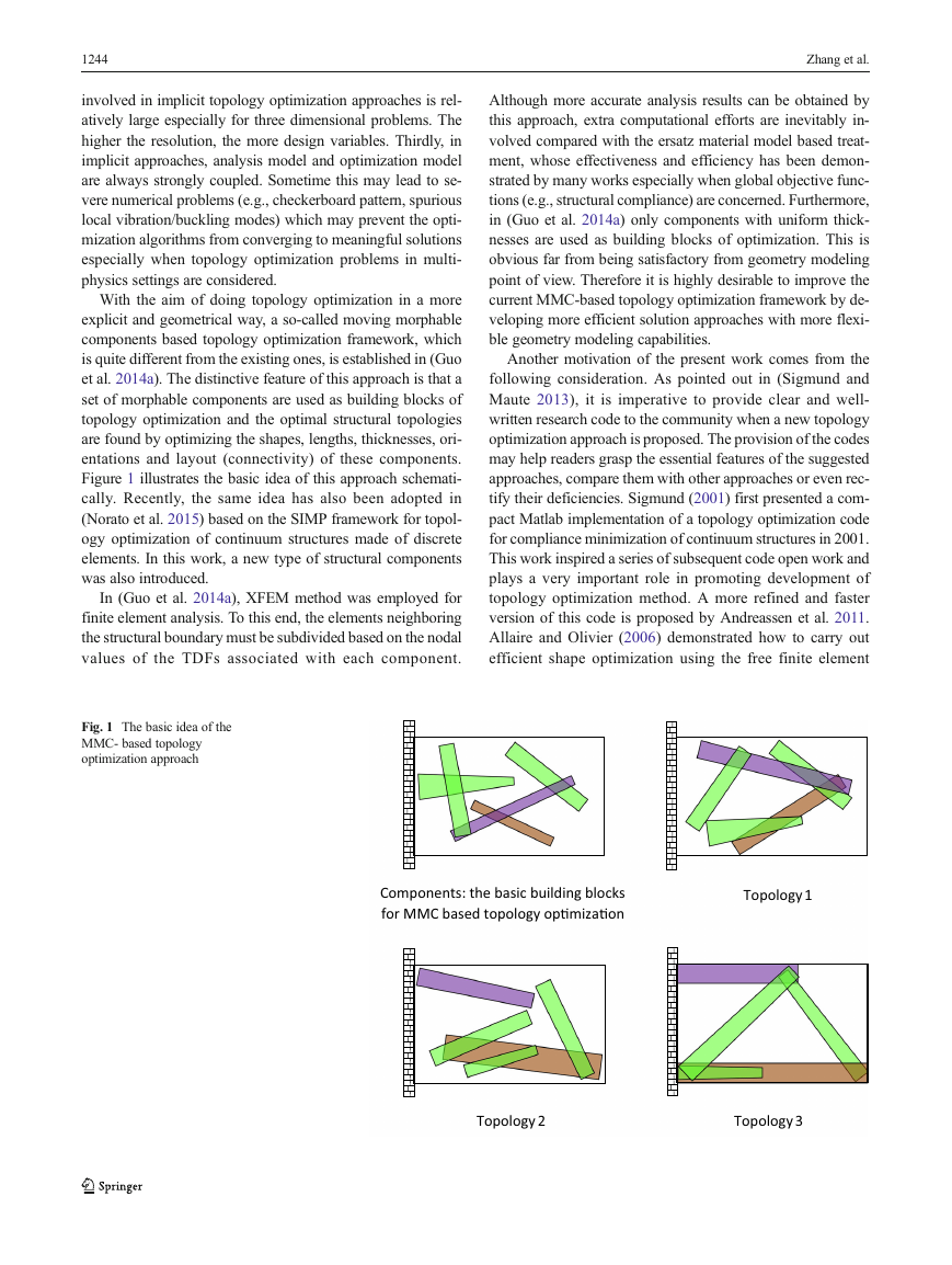
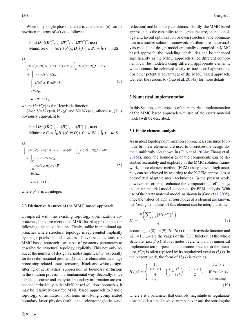
1244 Zhang et al. involved in implicit topology optimization approaches is rel- atively large especially for three dimensional problems. The higher the resolution, the more design variables. Thirdly, in implicit approaches, analysis model and optimization model are always strongly coupled. Sometime this may lead to se- vere numerical problems (e.g., checkerboard pattern, spurious local vibration/buckling modes) which may prevent the opti- mization algorithms from converging to meaningful solutions especially when topology optimization problems in multi- physics settings are considered. With the aim of doing topology optimization in a more explicit and geometrical way, a so-called moving morphable components based topology optimization framework, which is quite different from the existing ones, is established in (Guo et al. 2014a). The distinctive feature of this approach is that a set of morphable components are used as building blocks of topology optimization and the optimal structural topologies are found by optimizing the shapes, lengths, thicknesses, ori- entations and layout (connectivity) of these components. Figure 1 illustrates the basic idea of this approach schemati- cally. Recently, the same idea has also been adopted in (Norato et al. 2015) based on the SIMP framework for topol- ogy optimization of continuum structures made of discrete elements. In this work, a new type of structural components was also introduced. In (Guo et al. 2014a), XFEM method was employed for finite element analysis. To this end, the elements neighboring the structural boundary must be subdivided based on the nodal values of the TDFs associated with each component. Although more accurate analysis results can be obtained by this approach, extra computational efforts are inevitably in- volved compared with the ersatz material model based treat- ment, whose effectiveness and efficiency has been demon- strated by many works especially when global objective func- tions (e.g., structural compliance) are concerned. Furthermore, in (Guo et al. 2014a) only components with uniform thick- nesses are used as building blocks of optimization. This is obvious far from being satisfactory from geometry modeling point of view. Therefore it is highly desirable to improve the current MMC-based topology optimization framework by de- veloping more efficient solution approaches with more flexi- ble geometry modeling capabilities. Another motivation of the present work comes from the following consideration. As pointed out in (Sigmund and Maute 2013), it is imperative to provide clear and well- written research code to the community when a new topology optimization approach is proposed. The provision of the codes may help readers grasp the essential features of the suggested approaches, compare them with other approaches or even rec- tify their deficiencies. Sigmund (2001) first presented a com- pact Matlab implementation of a topology optimization code for compliance minimization of continuum structures in 2001. This work inspired a series of subsequent code open work and plays a very important role in promoting development of topology optimization method. A more refined and faster version of this code is proposed by Andreassen et al. 2011. Allaire and Olivier (2006) demonstrated how to carry out efficient shape optimization using the free finite element Fig. 1 The basic idea of the MMC- based topology optimization approach Components: the basic building blocks for MMC based topology opƟmizaƟon Topology 1 Topology 2 Topology 3
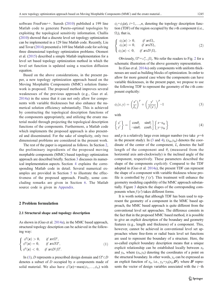
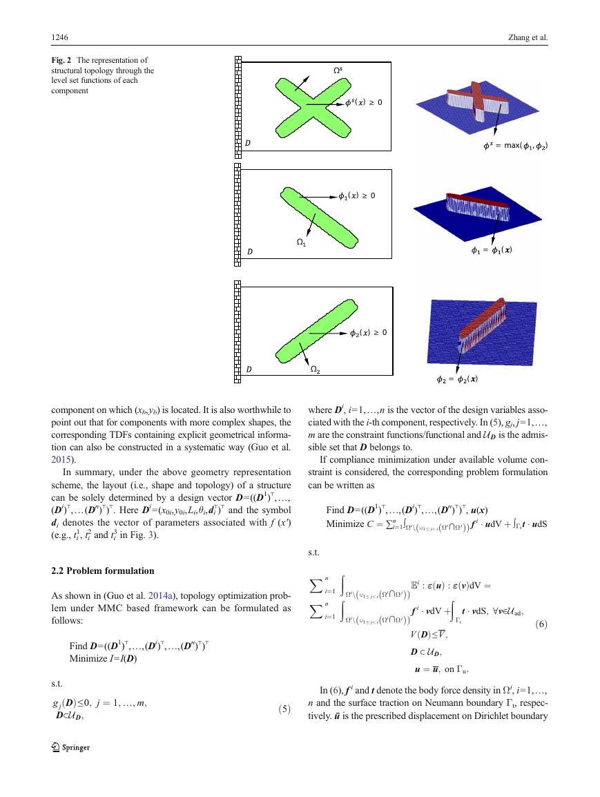
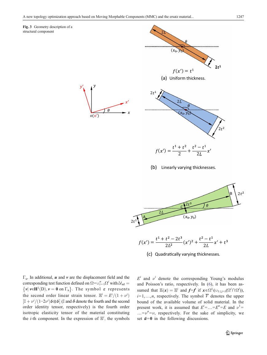
A new topology optimization approach based on Moving Morphable Components (MMC) and the ersatz material... 1245 ϕi=ϕi(x), i=1,…,n, denoting the topology description func- tion (TDF) of the region occupied by the i-th component (i.e., Ωi), that is, 8< : xð Þ > 0; ϕ xð Þ ¼ 0; i ϕ i xð Þ < 0; ϕ Obviously, Ωs=∪ i = 1 if x∈Ωi; if x∈∂Ωi; if x∈DnΩi: i software FreeFem++. Suresh (2010) published a 199 line Matlab code to generate Pareto-optimal topologies by exploiting the topological sensitivity information. Challis (2010) showed that a discrete level set topology optimization can be implemented in a 129 line Matlab code. Recently, Liu and Tovar (2014) presented a 169 line Matlab code for solving three dimensional topology optimization problems. Otomori et al. (2015) described a simple Matlab implementation for a level set based topology optimization method in which the level set function is updated using a reaction diffusion equation. Based on the above considerations, in the present pa- per, a new topology optimization approach based on the Moving Morphable Components (MMC) solution frame- work is proposed. The proposed method improves several weaknesses of the previous approach (e.g., Guo et al. 2014a) in the sense that it can not only allow for compo- nents with variable thicknesses but also enhance the nu- merical solution efficiency substantially. This is achieved by constructing the topological description functions of the components appropriately, and utilizing the ersatz ma- terial model through projecting the topological description functions of the components. Furthermore, a Matlab code which implements the proposed approach is also present- ed and disseminated. For the sake of simplicity, only two dimensional problems are considered in the present work. The rest of the paper is organized as follows. In Section 2, the preliminary ingredients of the proposed moving morphable components (MMC) based topology optimization approach are described briefly. Section 3 discusses its numer- ical implementation aspects. Section 4 explains the corre- sponding Matlab code in detail. Several numerical ex- amples are provided in Section 5 to illustrate the effec- tiveness of the proposed approach. Finally, some con- cluding remarks are given in Section 6. The Matlab source code is given in Appendix. 2 Problem formulation 2.1 Structural shape and topology description 8< : As shown in (Guo et al. 2014a), in the MMC based approach, structural topology description can be achieved in the follow- ing way: if x∈Ωs; if x∈∂Ωs; if x∈DnΩs: ϕs xð Þ > 0; ϕs xð Þ ¼ 0; ϕs xð Þ < 0; In (1), D represents a prescribed design domain and Ωs⊂D denotes a subset of D occupied by n components made of solid material. We also have ϕs(x)=max(ϕ1,…,ϕn) with ð1Þ ð2Þ ð3Þ ð4Þ n Ωi. We refer the readers to Fig. 2 for a schematic illustration of the above geometry representation. In (Guo et al. 2014a) only components with uniform thick- nesses are used as building blocks of optimization. In order to allow for more general case where the components can have variable thicknesses, in the present paper, we propose to use the following TDF to represent the geometry of the i-th com- ponent explicitly:  0   p þ Þ ¼ x Li  ¼ cosθi −sinθi ϕ ð i x; y   with 0 0 x y 0 y 0ð Þ f x   sinθi cosθi  p −1  x−x0i y−y0i and p is a relatively large even integer number (we take p=6 in the present study). In (3 and 4), (x0i,y0i) denotes the coor- dinate of the center of the component, Li denotes the half length of the component and θi (measured from the horizontal axis anti-clockwisely) is the inclined angle of the component, respectively. These parameters described the shape of the components explicitly. Compared to the TDF adopted in (Guo et al. 2014a), the present TDF can represent the shape of a component with variable thickness whose pro- file is controlled by f (x′). This treatment will enhance the geometry modeling capability of the MMC approach substan- tially. Figure 3 depicts the shapes of the corresponding com- ponents when f (x′) takes different forms. It is worth noting that although TDF has been used to rep- resent the geometry of a component in the MMC based ap- proach, the MMC based approach is quite different from the conventional level set approaches. The difference consists in the fact that in the proposed MMC based method, it is possible to give an explicit description of the boundary and geometry features (e.g., length and thickness) of a component. This, however, cannot be achieved in conventional level set ap- proaches where free-form or radial basis level set functions are used to represent the boundary of a structure. Here, the so-called explicit boundary description means that a unique explicit relationship can be established locally between xb and yb, where (xb,yb) denoting the coordinates of a point on the structural boundary. In other words, yb can be expressed as an explicit function of xb, i.e., yb=yb(xb;Di), where Di repre- sents the vector of design variables associated with the i−th
1246 Fig. 2 The representation of structural topology through the level set functions of each component component on which (xb,yb) is located. It is also worthwhile to point out that for components with more complex shapes, the corresponding TDFs containing explicit geometrical informa- tion can also be constructed in a systematic way (Guo et al. 2015). In summary, under the above geometry representation scheme, the layout (i.e., shape and topology) of a structure ⊤ can be solely determined by a design vector D=((D1) ,…, ⊤ ⊤ ⊤ ⊤ ⊤ ,…(Dn) . Here Di=(x0i,y0i,Li,θi,di (Di) and the symbol ) ) di denotes the vector of parameters associated with f (x′) (e.g., ti 3 in Fig. 3). 2 and ti 1, ti Zhang et al. = max( , ) = ( ) Ω ( ) ≥ 0 ( ) ≥ 0 Ω Ω ( ) ≥ 0 = ( ) where Di, i=1,…,n is the vector of the design variables asso- ciated with the i-th component, respectively. In (5), gj, j=1,…, m are the constraint functions/functional and UD is the admis- sible set that D belongs to. If compliance minimization under available volume con- straint is considered, the corresponding problem formulation can be written as ⊤ ⊤ ⊤ ⊤ Find D=((D1) , u(x) ,…,(Di) ,…,(Dn) ) Minimize C ¼ ∑n Þ f i  udV þ ∫Γt ð Þ ∫Ωin ∪1 ≤ j< i Ωi∩Ω j i¼1 ð t  udS 2.2 Problem formulation As shown in (Guo et al. 2014a), topology optimization prob- lem under MMC based framework can be formulated as follows: ⊤ ⊤ ⊤ ⊤ ,…,(Dn) ,…,(Di) Find D=((D1) ) Minimize I=I(D) s.t.X n X n Z Z i¼1 i¼1 ð ð ð ð Ωin ∪1 ≤ j< i Ωi∩Ω j Ωin ∪1 ≤ j< i Ωi∩Ω j Þ Þ t  vdS; ∀v∈Uad; ÞEi : ε uð Þ : ε vð ÞdV ¼ Z Þ f i  vdV þ V Dð Þ≤V ; D ⊂ UD; u ¼ u; on Γu: Γt ð6Þ s.t. Dð Þ≤0; j ¼ 1; …; m; g j D⊂UD; ð5Þ In (6), f i and t denote the body force density in Ωi, i=1,…, n and the surface traction on Neumann boundary Γt, respec- tively. ū is the prescribed displacement on Dirichlet boundary
A new topology optimization approach based on Moving Morphable Components (MMC) and the ersatz material... 1247 Fig. 3 Geometry description of a structural component o(o ) ð  Γu. In additional,u and v are the displacement field and the n Ωi with Uad ¼ corresponding test function defined on Ω=∪ i = 1 vj v∈H1 Dð Þ; v ¼ 0 on Γu : The symbol ε represents the second order linear strain tensor. Ei ¼ Ei= 1 þ νi Þ ½ Š (I and δ denote the fourth and the second I þ νi= 1−2νi order identity tensor, respectively) is the fourth order isotropic elasticity tensor of the material constituting the i-th component. In the expression of Ei; the symbols Þδ⊗δ ð 2 ( , ) ( ) = (a) Uniform thickness. 2 2 2 2 ( , ) 2 ( ) = + 2 + − 2 (b) Linearly varying thicknesses. B 2 2 A 2 2 C ( , ) ( ) = + − 2 2 ( ) + − 2 + (c) QuadraƟcally varying thicknesses. Ei and νi denote the corresponding Young’s modulus and Poisson’s ratio, respectively. In (6), it has been as- sumed that E xð Þ ¼ Ei and f=fi if x∈Ωi\(∪1≤j
1248 Zhang et al. When only single-phase material is considered, (6) can be rewritten in terms of ϕs(x) as follows: ⊤ ⊤ ⊤ ⊤ ,…,(Di) ,…,(Dn) , u(x) Find D=((D1) ) Minimize C ¼ ∫DH ϕs x; Dð ð Þ Þ f ⋅ udV þ ∫Γt t ⋅ udS Z s.t. Z ÞE : ε uð Þ : ε vð ÞdV ¼ D Z H ϕs x; Dð Þ ð Z þ ÞdV≤V ; Þ t ⋅ vdS;∀v∈Uad; Γt ð H ϕs x; Dð D⊂UD; u ¼ u; on Γu; D H ϕs x; Dð ð Þ Þf ⋅ vdV D ð7Þ reflection) and boundary conditions. Thirdly, the MMC based approach has the capability to integrate the size, shape, topol- ogy and layout optimization or even structural type optimiza- tion in a unified solution framework. Furthermore, since anal- ysis model and design model are totally decoupled in MMC based approach, the modeling capabilities can be enhanced significantly in the MMC approach since different compo- nents can be modeled using different appropriate elements, which cannot be achieved easily in traditional approaches. For other potential advantages of the MMC based approach, we refer the readers to (Guo et al. 2014a) for more details. 3 Numerical implementation where H=H(x) is the Heaviside function. Since H=H(x)=0, if x≤0 and H=H(x)=1, otherwise, (7) is obviously equivalent to In this Section, some aspects of the numerical implementation of the MMC based approach with use of the ersatz material model will be described. t ⋅ udS 3.1 Finite element analysis As in most topology optimization approaches, structured four- node bi-linear elements are used to discretize the design do- main uniformly. As shown in (Guo et al. 2014a; Zhang et al. 2015a), since the boundaries of the components can be de- scribed accurately and explicitly in the MMC solution frame- work, finite element method (FEM) analysis with high accu- racy can be achieved by resorting to the X-FEM approaches or body-fitted adaptive mesh techniques. In the present work, however, in order to enhance the computational efficiency, the ersatz material model is adopted for FEM analysis. With use of the ersatz material model, as shown in (Guo et al. 2005), once the values of TDF at four nodes of a element are known, the Young’s modulus of this element can be interpolated as  X 4    Ee ¼ E H ϕe i i¼1 q ; ð9Þ 4 according to (8). In (9), H=H(x) is the Heaviside function and ϕi e, i=1,…,4 are the values of the TDF function of the whole structure (i.e., ϕs(x)) at four nodes of element e. For numerical implementation purpose, as a common practice in the litera- ture, H(x) is often replaced by its regularized version Hϵ(x). In the present work, the form of Hϵ(x) is taken as 8>< >: 1; 3 1−αð Þ 4 α;   x ϵ − x3 3ϵ3 H ϵ xð Þ ¼ þ 1 þ α ð Þ 2 ; if x > ϵ; if −ϵ ≤x≤ϵ; otherwise; ð10Þ where ϵ is a parameter that controls magnitude of regulariza- tion and α is a small positive number to ensure the nonsingular Z s.t. D Z ð Z þ ⊤ ⊤ ⊤ ⊤ Find D=((D1) ,…,(Di) ,…,(Dn) , u(x) ) Minimize C ¼ ∫DH ϕs x; Dð ð Z ÞqE : ε uð Þ : ε vð ÞdV ¼ H ϕs x; Dð ð Þ H ϕs x; Dð ð Þ Þ f ⋅ udV þ ∫Γt Þ Þ Þf ⋅ vdV D ð8Þ ÞdV≤V ; Γt Þ t ⋅ vdS;∀v∈Uad; ð H ϕs x; Dð D⊂UD; u ¼ u; on Γu; D where q>1 is an integer. 2.3 Distinctive features of the MMC based approach Compared with the existing topology optimization ap- proaches, the afore-mentioned MMC based approach has the following distinctive features. Firstly, unlike in traditional ap- proaches where structural topology is represented implicitly by image pixels or nodal values of level set functions, the MMC based approach uses a set of geometry parameters to describe the structural topology explicitly. This not only re- duces the number of design variables significantly (especially for three dimensional problems!) but also eliminates the image processing related issues (ensuring black-and-white design, filtering of sensitivities, suppression of boundary diffusion) in the solution process in a fundamental way. Secondly, since explicit, accurate and analytical boundary information are em- bedded intrinsically in the MMC based solution approaches, it may be relatively easy for MMC based approach to handle topology optimization problems involving complicated boundary layer physics (turbulence, electromagnetic wave
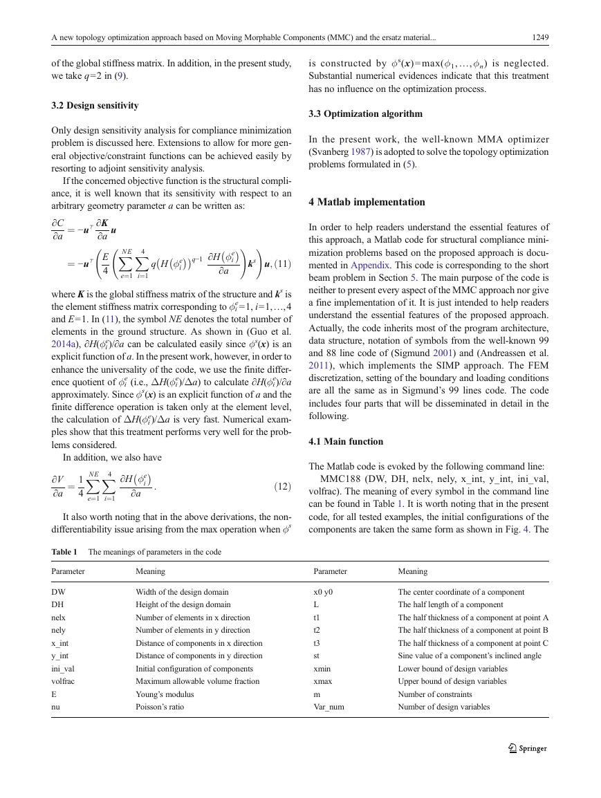
A new topology optimization approach based on Moving Morphable Components (MMC) and the ersatz material... 1249 of the global stiffness matrix. In addition, in the present study, we take q=2 in (9). is constructed by ϕs(x) = max(ϕ1, …, ϕn) is neglected. Substantial numerical evidences indicate that this treatment has no influence on the optimization process. 3.2 Design sensitivity 3.3 Optimization algorithm Only design sensitivity analysis for compliance minimization problem is discussed here. Extensions to allow for more gen- eral objective/constraint functions can be achieved easily by resorting to adjoint sensitivity analysis. In the present work, the well-known MMA optimizer (Svanberg 1987) is adopted to solve the topology optimization problems formulated in (5). If the concerned objective function is the structural compli- ance, it is well known that its sensitivity with respect to an arbitrary geometry parameter a can be written as: ∂C ∂a u XNE X4 q H ϕe i e¼1 i¼1 !  !   q−1 ∂H ϕe ∂a i ks u;ð11Þ ¼ −u⊤ ∂K ∂a ¼ −u⊤ E 4 where K is the global stiffness matrix of the structure and ks is the element stiffness matrix corresponding to ϕi e=1, i=1,…,4 and E=1. In (11), the symbol NE denotes the total number of elements in the ground structure. As shown in (Guo et al. 2014a), ∂H(ϕi e)/∂a can be calculated easily since ϕs(x) is an explicit function of a. In the present work, however, in order to enhance the universality of the code, we use the finite differ- e)/∂a ence quotient of ϕi approximately. Since ϕs(x) is an explicit function of a and the finite difference operation is taken only at the element level, the calculation of ΔH(ϕi e)/Δa is very fast. Numerical exam- ples show that this treatment performs very well for the prob- lems considered. e)/Δa) to calculate ∂H(ϕi e (i.e., ΔH(ϕi In addition, we also have XNE X4 e¼1 i¼1  ∂H ϕe i ∂a ∂V ∂a ¼ 1 4 : ð12Þ It also worth noting that in the above derivations, the non- differentiability issue arising from the max operation when ϕs Table 1 The meanings of parameters in the code 4 Matlab implementation In order to help readers understand the essential features of this approach, a Matlab code for structural compliance mini- mization problems based on the proposed approach is docu- mented in Appendix. This code is corresponding to the short beam problem in Section 5. The main purpose of the code is neither to present every aspect of the MMC approach nor give a fine implementation of it. It is just intended to help readers understand the essential features of the proposed approach. Actually, the code inherits most of the program architecture, data structure, notation of symbols from the well-known 99 and 88 line code of (Sigmund2001 ) and (Andreassen et al. 2011), which implements the SIMP approach. The FEM discretization, setting of the boundary and loading conditions are all the same as in Sigmund’s 99 lines code. The code includes four parts that will be disseminated in detail in the following. 4.1 Main function The Matlab code is evoked by the following command line: MMC188 (DW, DH, nelx, nely, x_int, y_int, ini_val, volfrac). The meaning of every symbol in the command line can be found in Table 1. It is worth noting that in the present code, for all tested examples, the initial configurations of the components are taken the same form as shown in Fig. 4. The Parameter Meaning Parameter Meaning DW DH nelx nely x_int y_int ini_val volfrac E nu Width of the design domain Height of the design domain Number of elements in x direction Number of elements in y direction Distance of components in x direction Distance of components in y direction Initial configuration of components Maximum allowable volume fraction Young’s modulus Poisson’s ratio x0 y0 L t1 t2 t3 st xmin xmax m Var_num The center coordinate of a component The half length of a component The half thickness of a component at point A The half thickness of a component at point B The half thickness of a component at point C Sine value of a component’s inclined angle Lower bound of design variables Upper bound of design variables Number of constraints Number of design variables
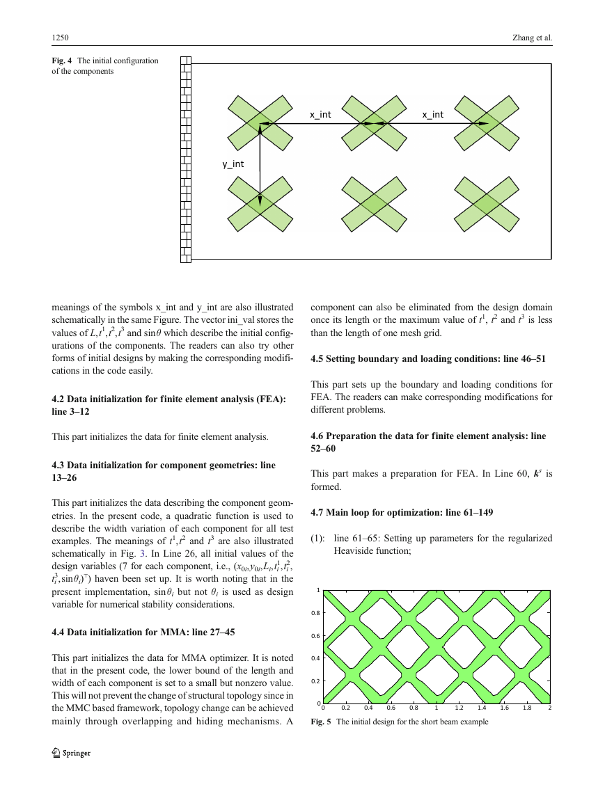
1250 Fig. 4 The initial configuration of the components Zhang et al. x_int x_int y_int meanings of the symbols x_int and y_int are also illustrated schematically in the same Figure. The vector ini_val stores the values of L,t1,t2,t3 and sinθ which describe the initial config- urations of the components. The readers can also try other forms of initial designs by making the corresponding modifi- cations in the code easily. 4.2 Data initialization for finite element analysis (FEA): line 3–12 This part initializes the data for finite element analysis. 4.3 Data initialization for component geometries: line 13–26 This part initializes the data describing the component geom- etries. In the present code, a quadratic function is used to describe the width variation of each component for all test examples. The meanings of t1,t2 and t3 are also illustrated schematically in Fig. 3. In Line 26, all initial values of the 1,ti 2, design variables (7 for each component, i.e., (x0i,y0i,Li,ti ⊤ 3,sinθi) ) haven been set up. It is worth noting that in the ti present implementation, sinθi but not θi is used as design variable for numerical stability considerations. 4.4 Data initialization for MMA: line 27–45 This part initializes the data for MMA optimizer. It is noted that in the present code, the lower bound of the length and width of each component is set to a small but nonzero value. This will not prevent the change of structural topology since in the MMC based framework, topology change can be achieved mainly through overlapping and hiding mechanisms. A component can also be eliminated from the design domain once its length or the maximum value of t1, t2 and t3 is less than the length of one mesh grid. 4.5 Setting boundary and loading conditions: line 46–51 This part sets up the boundary and loading conditions for FEA. The readers can make corresponding modifications for different problems. 4.6 Preparation the data for finite element analysis: line 52–60 This part makes a preparation for FEA. In Line 60, ks is formed. 4.7 Main loop for optimization: line 61–149 (1): line 61–65: Setting up parameters for the regularized Heaviside function; 1 0.8 0.6 0.4 0.2 0 0 0.2 0.4 0.6 0.8 1 1.2 1.4 1.6 1.8 2 Fig. 5 The initial design for the short beam example
分享到:
收藏