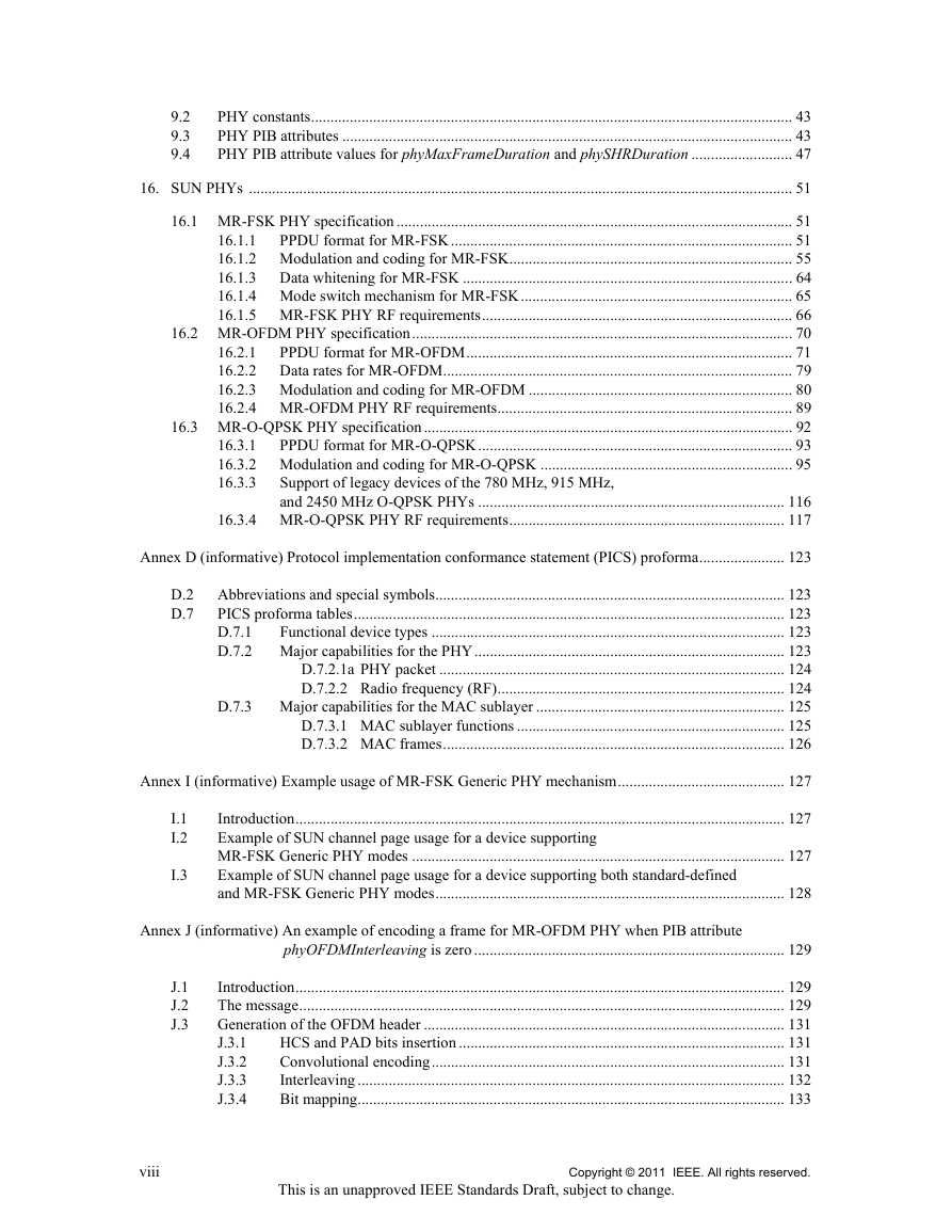
2. Normative references
3. Definitions, acronyms, and abbreviations
3.1 Definitions
3.2 Acronyms and abbreviations
4. General description
4.1a Introduction to smart metering utility network (SUN)
4.2a MR-FSK Generic PHY mechanism
4.2b Mode switch mechanism
4.2c Multi-PHY management (MPM) of the SUN WPAN
5. MAC protocol
5.1 MAC functional description
5.1.1 Channel access
5.1.1.2a MPM enhanced beacon (EB) timing
5.1.2 Starting and maintaining PANs
5.1.2.3 Starting and realigning a PAN
5.1.2.3.1 Starting a PAN
5.1.6 Transmission, reception, and acknowledgment
5.1.6.4 Use of acknowledgments and retransmissions
5.1.6.4.2 Acknowledgment
5.1.9 MPM procedure for inter-PHY coexistence
5.2 MAC frame formats
5.2.1 General MAC frame format
5.2.1.9 FCS field
5.2.2 Format of individual frame types
5.2.2.1 Beacon frame format
5.2.2.2 Data frame format
5.2.2.3 Acknowledgment frame format
5.2.2.4 MAC command frame format
5.2.4 Information Elements (IEs)
5.2.4.1 Coexistence Specification IE
5.2.4.2 SUN PHY Capabilities IE
5.2.4.3 MR-FSK Generic PHY Descriptor IE
5.2.4.4 Mode Switch Parameter Entry IE
6. MAC services
6.2 MAC management service
6.2.4 Communications notification primitives
6.2.4.1 MLME-BEACON-NOTIFY.indication
6.2.10 Primitives for channel scanning
6.2.10.1 MLME-SCAN.request
6.2.12 Primitives for updating the superframe configuration
6.2.12.1 MLME-START.request
6.3 MAC data service
6.3.1 MCPS-DATA.request
6.3.3 MCPS-DATA.indication
6.4 MAC constants and PIB attributes
6.4.1 MAC constants
6.4.2 MAC PIB attributes
6.4.3 Calculating PHY dependent MAC PIB values
8. General PHY requirements
8.1 General requirements and definitions
8.1.1 Operating frequency range
8.1.2 Channel assignments
8.1.2.1 Channel numbering for 780 MHz band
8.1.2.2 Channel numbering for 868 MHz, 915 MHz, and 2450 MHz bands
8.1.2.3 Channel numbering for 950 MHz PHYs
8.1.2.6 Channel numbering for SUN PHYs, except MR-O-QPSK PHY operating in the 868– 870 MHz band
8.1.2.7 Channel numbering for MR-O-QPSK PHY operating in the 868-870 MHz band
8.1.2.8 Channel pages for SUN PHYs
8.1.2.8.1 Channel page structure for standard-defined PHY modes
8.1.2.8.2 Channel page structure for MR-FSK Generic PHY modes
8.1.3 Minimum LIFS and SIFS periods
8.1.7 Receiver sensitivity definitions
8.1a Common signaling mode (CSM) for SUN PHY
8.2 General radio specifications
8.2.7 Clear channel assessment (CCA)
9. PHY services
9.2 PHY constants
9.3 PHY PIB attributes
9.4 PHY PIB attribute values for phyMaxFrameDuration and phySHRDuration
16. SUN PHYs
16.1 MR-FSK PHY specification
16.1.1 PPDU format for MR-FSK
16.1.1.1 Preamble field
16.1.1.2 SFD
16.1.1.3 PHR (without mode switch)
16.1.1.4 PHR for the mode switch packet
16.1.1.5 PSDU field
16.1.2 Modulation and coding for MR-FSK
16.1.2.1 Reference modulator diagram
16.1.2.2 Bit-to-symbol mapping
16.1.2.3 Modulation quality
16.1.2.3.1 Frequency deviation tolerance
16.1.2.3.2 Zero crossing tolerance
16.1.2.4 Forward error correction (FEC)
16.1.2.5 Code-symbol interleaving
16.1.3 Data whitening for MR-FSK
16.1.4 Mode switch mechanism for MR-FSK
16.1.5 MR-FSK PHY RF requirements
16.1.5.1 Operating frequency range
16.1.5.2 Regulatory compliance
16.1.5.3 Radio frequency tolerance
16.1.5.4 Channel switch time
16.1.5.5 Transmitter symbol rate
16.1.5.6 Transmit spectral mask
16.1.5.7 Receiver sensitivity
16.1.5.8 Receiver interference rejection
16.1.5.9 Tx-to-Rx turnaround time
16.1.5.10 Rx-to-Tx turnaround time
16.1.5.11 Transmit power
16.1.5.12 Receiver maximum input level of desired signal
16.1.5.13 Receiver ED
16.1.5.14 Link quality indicator
16.1.5.15 Clear channel assessment (CCA)
16.2 MR-OFDM PHY specification
16.2.1 PPDU format for MR-OFDM
16.2.1.1 Short Training field (STF)
16.2.1.1.1 Frequency domain STF
16.2.1.1.2 Time domain STF generation
16.2.1.1.3 Time domain STF repetition
16.2.1.1.4 STF normalization
16.2.1.2 Long Training field (LTF)
16.2.1.2.1 Frequency domain LTF
16.2.1.2.2 Time domain LTF generation
16.2.1.2.3 LTF normalization
16.2.1.3 PHR
16.2.1.4 PSDU field
16.2.2 Data rates for MR-OFDM
16.2.3 Modulation and coding for MR-OFDM
16.2.3.1 Reference modulator diagram
16.2.3.2 Bit-to-symbol mapping
16.2.3.3 PIB attribute values for phySymbolsPerOctet
16.2.3.4 Forward error correction (FEC)
16.2.3.5 Interleaver
16.2.3.6 Frequency spreading
16.2.3.6.1 Frequency spreading by 2x
16.2.3.6.2 Frequency spreading by 4x
16.2.3.6.3 No spreading
16.2.3.7 Pilot tones / null tones
16.2.3.8 Cyclic prefix
16.2.3.9 PPDU Tail Bit field (TAIL)
16.2.3.10 Pad bits (PAD)
16.2.3.11 Scrambler and scrambler seeds
16.2.4 MR-OFDM PHY RF requirements
16.2.4.1 Operating frequency range
16.2.4.2 Transmit power spectral density (PSD) mask
16.2.4.3 Receiver sensitivity
16.2.4.4 Adjacent channel rejection
16.2.4.5 Alternate channel rejection
16.2.4.6 Tx-to-Rx turnaround time
16.2.4.7 Rx-to-Tx turnaround time
16.2.4.8 Error-vector magnitude (EVM) definition
16.2.4.9 Transmit center frequency and symbol tolerance
16.2.4.10 Transmit power
16.2.4.11 Receiver maximum input level of desired signal
16.2.4.12 Receiver ED
16.2.4.13 Link quality indicator
16.2.4.14 Clear channel assessment (CCA)
16.3 MR-O-QPSK PHY specification
16.3.1 PPDU format for MR-O-QPSK
16.3.1.1 Preamble field
16.3.1.2 SFD
16.3.1.3 PHR
16.3.1.4 PSDU field
16.3.2 Modulation and coding for MR-O-QPSK
16.3.2.1 Reference modulator diagram
16.3.2.2 SHR coding and spreading
16.3.2.3 PHR coding and spreading
16.3.2.4 PSDU coding and spreading for DSSS
16.3.2.5 PSDU coding and spreading for MDSSS
16.3.2.6 Forward error correction (FEC)
16.3.2.7 Code-bit interleaving
16.3.2.8 Bit differential encoding (BDE)
16.3.2.9 DSSS bit-to-chip mapping
16.3.2.10 MDSSS bit-to-chip mapping
16.3.2.11 Chip whitening
16.3.2.12 Pilot insertion
16.3.2.13 Modulation parameters for O-QPSK
16.3.2.14 PIB attribute values for phySHRDuration, phyPHRDuration, phyPSDUDuration and phyMaxFrameDuration
16.3.3 Support of legacy devices of the 780 MHz, 915 MHz, and 2450 MHz O-QPSK PHYs
16.3.4 MR-O-QPSK PHY RF requirements
16.3.4.1 Operating frequency range
16.3.4.2 Transmit power spectral density (PSD) mask
16.3.4.3 Receiver sensitivity
16.3.4.4 Adjacent channel rejection
16.3.4.5 Tx-to-Rx turnaround time
16.3.4.6 Rx-to-Tx turnaround time
16.3.4.7 Error-vector magnitude (EVM) definition
16.3.4.8 Transmit center frequency and symbol tolerance
16.3.4.9 Transmit power
16.3.4.10 Receiver maximum input level of desired signal
16.3.4.11 Receiver ED
16.3.4.12 Link quality indicator
16.3.4.13 Clear channel assessment (CCA)
Annex D
D.2 Abbreviations and special symbols
D.7 PICS proforma tables
D.7.1 Functional device types
D.7.2 Major capabilities for the PHY
D.7.2.1a PHY packet
D.7.2.2 Radio frequency (RF)
D.7.3 Major capabilities for the MAC sublayer
D.7.3.1 MAC sublayer functions
D.7.3.2 MAC frames
Annex I
I.1 Introduction
I.2 Example of SUN channel page usage for a device supporting MR-FSK Generic PHY modes
I.3 Example of SUN channel page usage for a device supporting both standard-defined and MR-FSK Generic PHY modes
Annex J
J.1 Introduction
J.2 The message
J.3 Generation of the OFDM header
J.3.1 HCS and PAD bits insertion
J.3.2 Convolutional encoding
J.3.3 Interleaving
J.3.4 Bit mapping
J.3.5 Frequency spreading
J.4 Generation of the data symbols
J.4.1 PAD insertion and data scrambling
J.4.2 Convolutional encoding and puncturing
J.4.3 Interleaving
J.4.4 Bit mapping
J.4.5 Frequency spreading
J.5 Conversion from frequency domain to time domain
J.5.1 Pilot, DC, and guard tone insertion
J.5.2 Time domain OFDM header and payload
J.6 Generation of the preamble
J.6.1 Generation of the STF
J.6.2 Generation of the LTF
J.7 The entire packet
Annex K
K.1 Introduction
K.2 The message
K.3 Generation of the OFDM header
K.3.1 HCS and PAD bits insertion
K.3.2 Convolutional encoding
K.3.3 Interleaving
K.3.4 Bit mapping
K.3.5 Frequency spreading
K.4 Generation of the data symbols
K.4.1 PAD insertion and data scrambling
K.4.2 Convolutional encoding and puncturing
K.4.3 Interleaving
K.4.4 Bit mapping
K.4.5 Frequency spreading
K.5 Conversion from frequency domain to time domain
K.5.1 Pilot, DC, and guard tone insertion
K.5.2 Time domain OFDM header and payload
Annex L
L.1 Introduction
L.2 The message
L.3 Generation of the SHR
L.4 Generation of the PHR
L.5 Generation of the PSDU




 2023年江西萍乡中考道德与法治真题及答案.doc
 2012年重庆南川中考生物真题及答案.doc
 2013年江西师范大学地理学综合及文艺理论基础考研真题.doc
 2020年四川甘孜小升初语文真题及答案I卷.doc
 2020年注册岩土工程师专业基础考试真题及答案.doc
 2023-2024学年福建省厦门市九年级上学期数学月考试题及答案.doc
 2021-2022学年辽宁省沈阳市大东区九年级上学期语文期末试题及答案.doc
 2022-2023学年北京东城区初三第一学期物理期末试卷及答案.doc
 2018上半年江西教师资格初中地理学科知识与教学能力真题及答案.doc
 2012年河北国家公务员申论考试真题及答案-省级.doc
 2020-2021学年江苏省扬州市江都区邵樊片九年级上学期数学第一次质量检测试题及答案.doc
 2022下半年黑龙江教师资格证中学综合素质真题及答案.doc