logo资料库

万兆四口PHY芯片NetLogic NLP2042详细手册.pdf

第1页 / 共246页
第2页 / 共246页
第3页 / 共246页
第4页 / 共246页
第5页 / 共246页
第6页 / 共246页
第7页 / 共246页
第8页 / 共246页
资料共246页,剩余部分请下载后查看
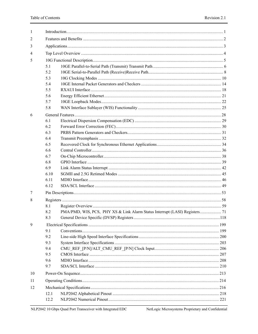
1 Introduction
2 Features and Benefits
3 Applications
4 Top Level Overview
5 10G Functional Description
5.1 10GE Parallel-to-Serial Path (Transmit) Transmit Path
5.1.1 XAUI/RXAUI Parallel Receive (TXDATA)
5.1.2 Word Align and 8b/10b Decode
5.1.3 Scrambler/Encoder, FIFO, and Rate Adjustment
5.1.4 Serial OutputLine Side Transmitter (HSTXDATA)
5.1.5 CMU Loss of Lock (CMU_LOL)
5.1.6 Output Data Transmission Enable and Lower Power Startup (LPS) Mode
5.2 10GE Serial-to-Parallel Path (Receive)Receive Path
5.2.1 Line Side Receiver (HSRXDATA)
5.2.2 10GBASE-xR, 64b/66b Serial Descramble/Decode, Alignment, Receive FIFO
5.2.3 Receive 8b/10b Encoding
5.2.4 Parallel Transmit (RXDATA)
5.3 10G Clocking Modes
5.3.1 Basic 10G LAN Clocking
5.3.2 Basic 10G SAN Clocking
5.3.3 WAN Clocking
5.3.4 One XO LAN/WAN/SAN Clocking (155.52 MHz XO)
5.4 10GE Internal Packet Generators and Checkers
5.4.1 Configuring the Packet Generator
5.4.2 Initiating Packet Transmission
5.4.3 Using the Checker
5.4.4 Example Sequences of Operation
5.4.5 CJPAT Generation
5.5 RXAUI Interface
5.6 Energy Efficient Ethernet
5.7 10GE Loopback Modes
5.7.1 System Loopback Modes (TXDATA to RXDATA)
5.7.2 Line Loopback Modes (HSRXDATA to HSTXDATA)
5.8 WAN Interface Sublayer (WIS) Functionality
5.8.1 WIS Encoding
5.8.2 WIS Decoding
6 General Features
6.1 Electrical Dispersion Compensation (EDC)
6.2 Forward Error Correction (FEC)
6.3 PRBS Pattern Generators and Checkers
6.4 Transmit Preemphasis
6.5 Recovered Clock for Synchronous Ethernet Applications
6.6 Central Controller
6.7 On-Chip Microcontroller
6.8 GPIO Interface
6.8.1 GPIO Control & Status Registers Configuration
6.8.2 Input Mode
6.8.3 Output Mode
6.8.4 Traffic Indication Mode
6.8.5 Prob Mode
6.9 Link Alarm Status Interrupt
6.9.1 LS_ALARM
6.9.2 TX_ALARM
6.9.3 RX_ALARM
6.9.4 Delta Interrupt ALARM
6.9.5 GPIO Interrupt ALARM
6.9.6 Soft LASI
6.10 SGMII and 2.5G Retimed Modes
6.11 MDIO Interface
6.11.1 MDIO Address Transaction
6.11.2 MDIO Read Transaction
6.11.3 MDIO Read Increment Transaction
6.11.4 MDIO Write Transaction
6.11.5 Proprietary MDIO Write Increment Transaction
6.11.6 Proprietary MDIO Broadcast Write
6.11.7 Proprietary MDIO Preamble Suppression
6.12 SDA/SCL Interface
6.12.1 Format for Serial Bus Operations
6.12.2 SDA/SCL Byte-by-Byte Operations
6.12.3 Multi-master Operation and Arbitration
6.12.4 Copy Engines
7 Pin Descriptions
8 Registers
8.1 Register Overview
8.2 PMA/PMD, WIS, PCS, PHY XS & Link Alarm Status Interrupt (LASI) Registers
8.2.1 PMA/PMD Control and Status Registers
8.2.2 WIS Registers
8.2.3 PCS Registers
8.2.4 PHY XS Registers
8.2.5 Link Alarm Status Interrupt (LASI) Registers
8.3 General Device Specific (DVSP) Registers
8.3.1 General Control and Status Registers
8.3.2 EDC Registers
8.3.3 Line Interface Transmit Control and Status Registers
8.3.4 System Interface Transmit Control and Status Registers
8.3.5 System Interface Receive Control and Status Registers
8.3.6 RXAUI Transmit Control and Status Registers
8.3.7 RXAUI Receive Control and Status Registers
8.3.8 BER and Packet Generator/Checker Registers
8.3.9 GBase Traffic Registers
8.3.10 CMU Registers
8.3.11 Clock Output Configuration Registers
8.3.12 FIFO Pointer Registers
8.3.13 SGMII and RSGMII Control Registers
8.3.14 Energy Efficient Ethernet (EEE) Registers
8.3.15 FIFO Pointer Registers
8.3.16 Low Speed I/O Configuration Registers
8.3.17 Power Control Registers
8.3.18 Read-Modify-Write Engine Control and Status Registers
8.3.19 Embedded Micro-Controller Registers
8.3.20 Delta Interrupt Registers
8.3.21 FEC Registers
9 Electrical Specifications
9.1 Conventions
9.2 Line-side High Speed Interface Specifications
9.3 System Interface Specifications
9.3.1 SerDes Inputs (TXDATA)
9.3.2 SerDes Outputs (RXDATA)
9.3.3 SerDes Specification Tables
9.4 CMU_REF_[P/N]/ALT_CMU_REF_[P/N] Clock Input
9.5 CMOS Interface
9.6 MDIO Interface
9.7 SDA/SCL Interface
10 Power-On Sequence
11 Operating Conditions
12 Mechanical Specifications
12.1 NLP2042 Alphabetical Pinout
12.2 NLP2042 Numerical Pinout
13 Boundary Scan Test Access Port (TAP)
14 NLP2042 Ordering Information
14.1 Commercial Temperature
14.2 Industrial Temperature
NLP2042 10 Gbps Quad Port Transceiver with Integrated EDC Datasheet Device Revision: A4 Datasheet Revision 2.1 February 1, 2012 NetLogic Microsystems 3975 Freedom Circle, Suite 900 Santa Clara, CA 95054 USA (408) 454-3000 www.netlogicmicro.com support@netlogicmicro.com
Copyright © 2012 Netlogic Microsystems, Inc. All rights reserved. Netlogic Microsystems, the stylized Netlogic Micro- systems logo, and all other words and logos that are identified as trademarks are, unless noted otherwise, the trademarks of Netlogic Microsystems Inc. in the U.S. and other countries. All other trademarks mentioned in this document are the property of their respective owners.
Revision 2.1 Revision History Date April 10, 2010 December 11, 2010 Page Number Entire document Entire document May 25, 2011 2, 162, 171, 172, 179, 182, 193, 197 August 8, 2011 Entire document January 5, 2012 227, 228 February 1, 2012 209, 228, 229 Revision History Old Rev New Rev - 0.92 0.96 0.96 1.0 2.0 0.92 0.96 0.97 1.0 2.0 2.1 Description First draft of NLP2042 datasheet Conversion to new template Revision number updated to reflect latest PCN; features &benefits and operating conditons tables updated; figures 49, 50, 56, table 375, BSDL and ordering tables updated Ordering table updated to reflect differen t RoHS options and features Ordering table updated to reflect device revision A4 IOL,MDIO value corrected in MDIO AC Characteristics table under section 9; industrial grade temperature ordering options table added; NLP2042 10 Gbps Quad Port Transceiver with Integrated EDC NetLogic Microsystems Proprietary and Confidential
Table of Contents Revision 2.1 1 2 3 4 5 6 7 8 9 10 11 12 Introduction..................................................................................................................................................... 1 Features and Benefits ..................................................................................................................................... 2 Applications.................................................................................................................................................... 3 Top Level Overview ....................................................................................................................................... 4 10G Functional Description............................................................................................................................ 5 10GE Parallel-to-Serial Path (Transmit) Transmit Path................................................................... 6 5.1 10GE Serial-to-Parallel Path (Receive)Receive Path....................................................................... 8 5.2 5.3 10G Clocking Modes ..................................................................................................................... 10 10GE Internal Packet Generators and Checkers ............................................................................ 14 5.4 RXAUI Interface............................................................................................................................ 18 5.5 5.6 Energy Efficient Ethernet............................................................................................................... 21 10GE Loopback Modes.................................................................................................................. 22 5.7 5.8 WAN Interface Sublayer (WIS) Functionality............................................................................... 25 General Features ........................................................................................................................................... 28 6.1 Electrical Dispersion Compensation (EDC) .................................................................................. 29 Forward Error Correction (FEC).................................................................................................... 30 6.2 PRBS Pattern Generators and Checkers......................................................................................... 31 6.3 6.4 Transmit Preemphasis .................................................................................................................... 32 Recovered Clock for Synchronous Ethernet Applications............................................................. 34 6.5 Central Controller........................................................................................................................... 36 6.6 On-Chip Microcontroller................................................................................................................ 38 6.7 6.8 GPIO Interface ............................................................................................................................... 39 Link Alarm Status Interrupt ........................................................................................................... 42 6.9 SGMII and 2.5G Retimed Modes .................................................................................................. 45 6.10 6.11 MDIO Interface.............................................................................................................................. 46 6.12 SDA/SCL Interface ........................................................................................................................ 49 Pin Descriptions............................................................................................................................................ 53 Registers ....................................................................................................................................................... 58 Register Overview.......................................................................................................................... 59 8.1 PMA/PMD, WIS, PCS, PHY XS & Link Alarm Status Interrupt (LASI) Registers.................... 71 8.2 8.3 General Device Specific (DVSP) Registers..................................................................................118 Electrical Specifications ............................................................................................................................ 199 Conventions.................................................................................................................................. 199 9.1 Line-side High Speed Interface Specifications ............................................................................ 200 9.2 9.3 System Interface Specifications ................................................................................................... 203 CMU_REF_[P/N]/ALT_CMU_REF_[P/N] Clock Input............................................................. 206 9.4 CMOS Interface ........................................................................................................................... 207 9.5 9.6 MDIO Interface............................................................................................................................ 208 9.7 SDA/SCL Interface ...................................................................................................................... 210 Power-On Sequence.................................................................................................................................... 213 Operating Conditions.................................................................................................................................. 214 Mechanical Specifications.......................................................................................................................... 216 NLP2042 Alphabetical Pinout ..................................................................................................... 218 12.1 12.2 NLP2042 Numerical Pinout......................................................................................................... 221 NLP2042 10 Gbps Quad Port Transceiver with Integrated EDC NetLogic Microsystems Proprietary and Confidential
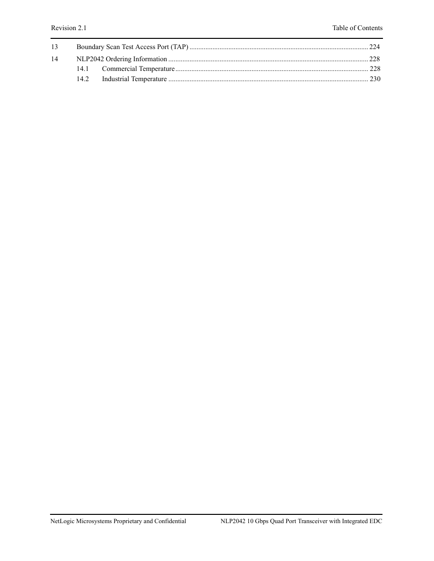
Revision 2.1 Table of Contents 13 14 Boundary Scan Test Access Port (TAP) ..................................................................................................... 224 NLP2042 Ordering Information ................................................................................................................. 228 Commercial Temperature............................................................................................................. 228 14.1 14.2 Industrial Temperature ................................................................................................................. 230 NetLogic Microsystems Proprietary and Confidential NLP2042 10 Gbps Quad Port Transceiver with Integrated EDC
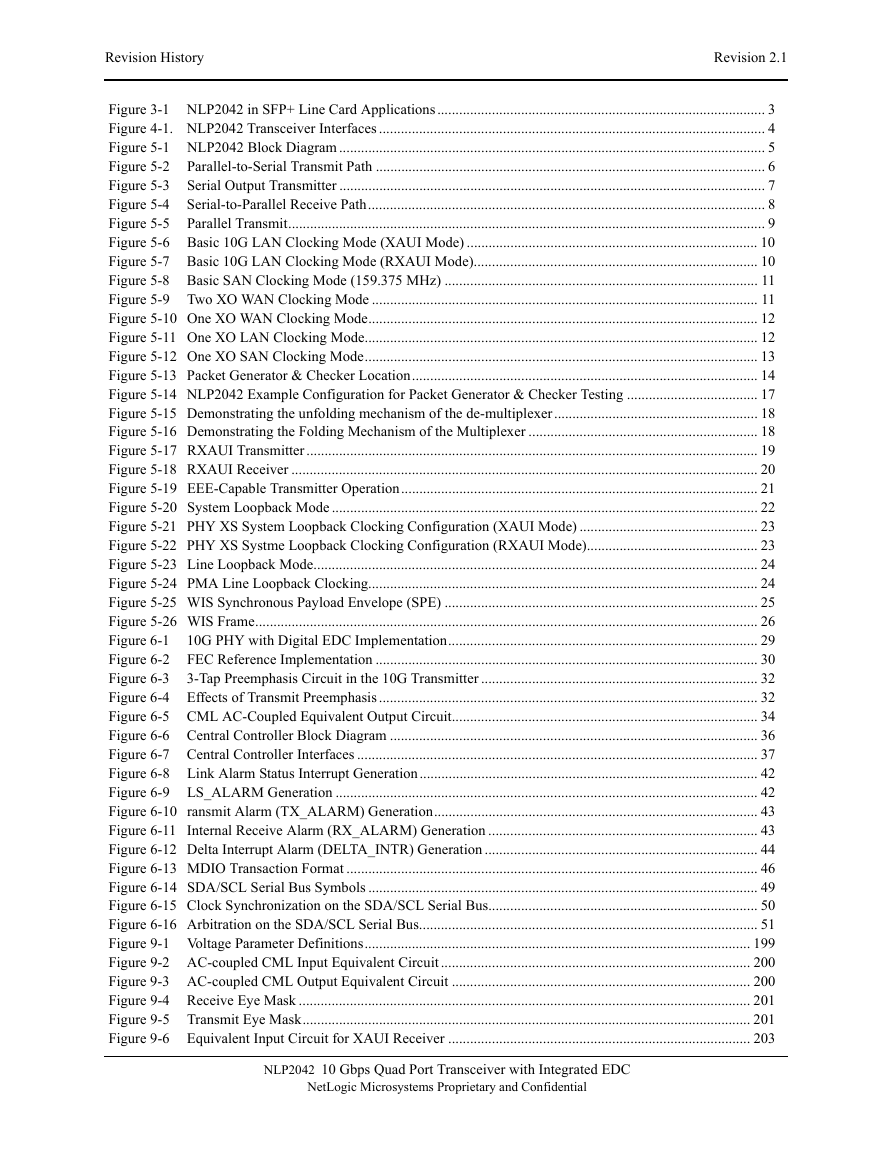
Revision History Revision 2.1 Figure 3-1 NLP2042 in SFP+ Line Card Applications.......................................................................................... 3 Figure 4-1. NLP2042 Transceiver Interfaces .......................................................................................................... 4 Figure 5-1 NLP2042 Block Diagram ..................................................................................................................... 5 Parallel-to-Serial Transmit Path ........................................................................................................... 6 Figure 5-2 Figure 5-3 Serial Output Transmitter ..................................................................................................................... 7 Serial-to-Parallel Receive Path............................................................................................................. 8 Figure 5-4 Figure 5-5 Parallel Transmit................................................................................................................................... 9 Figure 5-6 Basic 10G LAN Clocking Mode (XAUI Mode) ................................................................................ 10 Figure 5-7 Basic 10G LAN Clocking Mode (RXAUI Mode).............................................................................. 10 Figure 5-8 Basic SAN Clocking Mode (159.375 MHz) ...................................................................................... 11 Figure 5-9 Two XO WAN Clocking Mode .......................................................................................................... 11 Figure 5-10 One XO WAN Clocking Mode........................................................................................................... 12 Figure 5-11 One XO LAN Clocking Mode............................................................................................................ 12 Figure 5-12 One XO SAN Clocking Mode............................................................................................................ 13 Figure 5-13 Packet Generator & Checker Location............................................................................................... 14 Figure 5-14 NLP2042 Example Configuration for Packet Generator & Checker Testing .................................... 17 Figure 5-15 Demonstrating the unfolding mechanism of the de-multiplexer........................................................ 18 Figure 5-16 Demonstrating the Folding Mechanism of the Multiplexer ............................................................... 18 Figure 5-17 RXAUI Transmitter............................................................................................................................ 19 Figure 5-18 RXAUI Receiver ................................................................................................................................ 20 Figure 5-19 EEE-Capable Transmitter Operation.................................................................................................. 21 Figure 5-20 System Loopback Mode ..................................................................................................................... 22 Figure 5-21 PHY XS System Loopback Clocking Configuration (XAUI Mode) ................................................. 23 Figure 5-22 PHY XS Systme Loopback Clocking Configuration (RXAUI Mode)............................................... 23 Figure 5-23 Line Loopback Mode.......................................................................................................................... 24 Figure 5-24 PMA Line Loopback Clocking........................................................................................................... 24 Figure 5-25 WIS Synchronous Payload Envelope (SPE) ...................................................................................... 25 Figure 5-26 WIS Frame.......................................................................................................................................... 26 10G PHY with Digital EDC Implementation..................................................................................... 29 Figure 6-1 FEC Reference Implementation ......................................................................................................... 30 Figure 6-2 Figure 6-3 3-Tap Preemphasis Circuit in the 10G Transmitter ............................................................................ 32 Figure 6-4 Effects of Transmit Preemphasis ........................................................................................................ 32 Figure 6-5 CML AC-Coupled Equivalent Output Circuit.................................................................................... 34 Figure 6-6 Central Controller Block Diagram ..................................................................................................... 36 Figure 6-7 Central Controller Interfaces .............................................................................................................. 37 Figure 6-8 Link Alarm Status Interrupt Generation............................................................................................. 42 Figure 6-9 LS_ALARM Generation .................................................................................................................... 42 Figure 6-10 ransmit Alarm (TX_ALARM) Generation......................................................................................... 43 Figure 6-11 Internal Receive Alarm (RX_ALARM) Generation .......................................................................... 43 Figure 6-12 Delta Interrupt Alarm (DELTA_INTR) Generation ........................................................................... 44 Figure 6-13 MDIO Transaction Format ................................................................................................................. 46 Figure 6-14 SDA/SCL Serial Bus Symbols ........................................................................................................... 49 Figure 6-15 Clock Synchronization on the SDA/SCL Serial Bus.......................................................................... 50 Figure 6-16 Arbitration on the SDA/SCL Serial Bus............................................................................................. 51 Figure 9-1 Voltage Parameter Definitions.......................................................................................................... 199 Figure 9-2 AC-coupled CML Input Equivalent Circuit ..................................................................................... 200 Figure 9-3 AC-coupled CML Output Equivalent Circuit .................................................................................. 200 Figure 9-4 Receive Eye Mask ............................................................................................................................ 201 Figure 9-5 Transmit Eye Mask........................................................................................................................... 201 Figure 9-6 Equivalent Input Circuit for XAUI Receiver ................................................................................... 203 NLP2042 10 Gbps Quad Port Transceiver with Integrated EDC NetLogic Microsystems Proprietary and Confidential
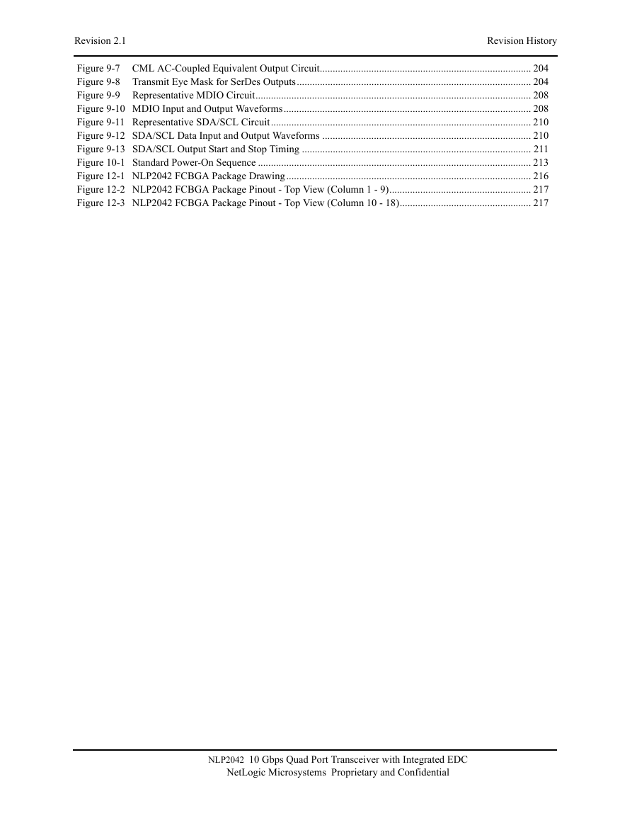
Revision 2.1 Revision History Figure 9-7 CML AC-Coupled Equivalent Output Circuit.................................................................................. 204 Figure 9-8 Transmit Eye Mask for SerDes Outputs........................................................................................... 204 Figure 9-9 Representative MDIO Circuit........................................................................................................... 208 Figure 9-10 MDIO Input and Output Waveforms................................................................................................ 208 Figure 9-11 Representative SDA/SCL Circuit..................................................................................................... 210 Figure 9-12 SDA/SCL Data Input and Output Waveforms ................................................................................. 210 Figure 9-13 SDA/SCL Output Start and Stop Timing ......................................................................................... 211 Figure 10-1 Standard Power-On Sequence .......................................................................................................... 213 Figure 12-1 NLP2042 FCBGA Package Drawing............................................................................................... 216 Figure 12-2 NLP2042 FCBGA Package Pinout - Top View (Column 1 - 9)....................................................... 217 Figure 12-3 NLP2042 FCBGA Package Pinout - Top View (Column 10 - 18)................................................... 217 NLP2042 10 Gbps Quad Port Transceiver with Integrated EDC NetLogic Microsystems Proprietary and Confidential
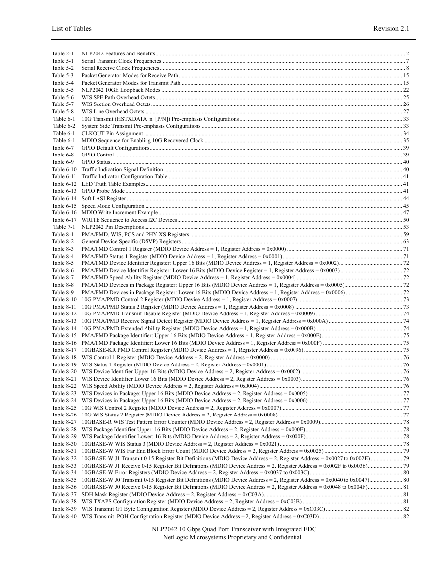
List of Tables Revision 2.1 Table 2-1 NLP2042 Features and Benefits............................................................................................................................................................................. 2 Table 5-1 Serial Transmit Clock Frequencies ........................................................................................................................................................................ 7 Serial Receive Clock Frequencies.......................................................................................................................................................................... 8 Table 5-2 Packet Generator Modes for Receive Path........................................................................................................................................................... 15 Table 5-3 Table 5-4 Packet Generator Modes for Transmit Path ......................................................................................................................................................... 15 Table 5-5 NLP2042 10GE Loopback Modes ....................................................................................................................................................................... 22 Table 5-6 WIS SPE Path Overhead Octets........................................................................................................................................................................... 25 Table 5-7 WIS Section Overhead Octets.............................................................................................................................................................................. 26 Table 5-8 WIS Line Overhead Octets................................................................................................................................................................................... 27 Table 6-1 10G Transmit (HSTXDATA_n_[P/N]) Pre-emphasis Configurations................................................................................................................. 33 Table 6-2 System Side Transmit Pre-emphasis Configurations ........................................................................................................................................... 33 Table 6-1 CLKOUT Pin Assignment ................................................................................................................................................................................... 34 Table 6-1 MDIO Sequence for Enabling 10G Recovered Clock ......................................................................................................................................... 35 Table 6-7 GPIO Default Configurations............................................................................................................................................................................... 39 Table 6-8 GPIO Control ....................................................................................................................................................................................................... 39 Table 6-9 GPIO Status.......................................................................................................................................................................................................... 40 Table 6-10 Traffic Indication Signal Definition ..................................................................................................................................................................... 40 Table 6-11 Traffic Indicator Configuration Table .................................................................................................................................................................. 41 Table 6-12 LED Truth Table Examples.................................................................................................................................................................................. 41 Table 6-13 GPIO Probe Mode................................................................................................................................................................................................ 41 Table 6-14 Soft LASI Register ............................................................................................................................................................................................... 44 Table 6-15 Speed Mode Configuration .................................................................................................................................................................................. 45 Table 6-16 MDIO Write Increment Example......................................................................................................................................................................... 47 Table 6-17 WRITE Sequence to Access I2C Devices............................................................................................................................................................ 50 Table 7-1 NLP2042 Pin Descriptions................................................................................................................................................................................... 53 Table 8-1 PMA/PMD, WIS, PCS and PHY XS Registers ................................................................................................................................................... 59 Table 8-2 General Device Specific (DSVP) Registers ......................................................................................................................................................... 63 PMA/PMD Control 1 Register (MDIO Device Address = 1, Register Address = 0x0000) ................................................................................ 71 Table 8-3 PMA/PMD Status 1 Register (MDIO Device Address = 1, Register Address = 0x0001)................................................................................... 71 Table 8-4 PMA/PMD Device Identifier Register: Upper 16 Bits (MDIO Device Address = 1, Register Address = 0x0002)............................................ 72 Table 8-5 PMA/PMD Device Identifier Register: Lower 16 Bits (MDIO Device Register = 1, Register Address = 0x0003) ........................................... 72 Table 8-6 Table 8-7 PMA/PMD Speed Ability Register (MDIO Device Address = 1, Register Address = 0x0004) ......................................................................... 72 PMA/PMD Devices in Package Register: Upper 16 Bits (MDIO Device Address = 1, Register Address = 0x0005)........................................ 72 Table 8-8 Table 8-9 PMA/PMD Devices in Package Register: Lower 16 Bits (MDIO Device Address = 1, Register Address = 0x0006) ....................................... 72 Table 8-10 10G PMA/PMD Control 2 Register (MDIO Device Address = 1, Register Address = 0x0007) ........................................................................ 73 Table 8-11 10G PMA/PMD Status 2 Register (MDIO Device Address = 1, Register Address = 0x0008)........................................................................... 73 Table 8-12 10G PMA/PMD Transmit Disable Register (MDIO Device Address = 1, Register Address = 0x0009) ............................................................ 74 Table 8-13 10G PMA/PMD Receive Signal Detect Register (MDIO Device Address = 1, Register Address = 0x000A) ................................................... 74 Table 8-14 10G PMA/PMD Extended Ability Register (MDIO Device Address = 1, Register Address = 0x000B) ........................................................... 74 Table 8-15 PMA/PMD Package Identifier: Upper 16 Bits (MDIO Device Address = 1, Register Address = 0x000E)........................................................ 75 Table 8-16 PMA/PMD Package Identifier: Lower 16 Bits (MDIO Device Address = 1, Register Address = 0x000F) ....................................................... 75 Table 8-17 10GBASE-KR PMD Control Register (MDIO Device Address = 1, Register Address = 0x0096) .................................................................... 75 Table 8-18 WIS Control 1 Register (MDIO Device Address = 2, Register Address = 0x0000) ........................................................................................... 76 Table 8-19 WIS Status 1 Register (MDIO Device Address = 2, Register Address = 0x0001).............................................................................................. 76 Table 8-20 WIS Device Identifier Upper 16 Bits (MDIO Device Address = 2, Register Address = 0x0002) ...................................................................... 76 Table 8-21 WIS Device Identifier Lower 16 Bits (MDIO Device Address = 2, Register Address = 0x0003)...................................................................... 76 Table 8-22 WIS Speed Ability (MDIO Device Address = 2, Register Address = 0x0004)................................................................................................... 76 Table 8-23 WIS Devices in Package: Upper 16 Bits (MDIO Device Address = 2, Register Address = 0x0005) ................................................................. 77 Table 8-24 WIS Devices in Package: Upper 16 Bits (MDIO Device Address = 2, Register Address = 0x0006) ................................................................. 77 Table 8-25 10G WIS Control 2 Register (MDIO Device Address = 2, Register Address = 0x0007).................................................................................... 77 Table 8-26 10G WIS Status 2 Register (MDIO Device Address = 2, Register Address = 0x0008) ...................................................................................... 77 Table 8-27 10GBASE-R WIS Test Pattern Error Counter (MDIO Device Address = 2, Register Address = 0x0009)......................................................... 78 Table 8-28 WIS Package Identifier Upper: 16 Bits (MDIO Device Address = 2, Register Address = 0x000E)................................................................... 78 Table 8-29 WIS Package Identifier Lower: 16 Bits (MDIO Device Address = 2, Register Address = 0x000F)................................................................... 78 Table 8-30 10GBASE-W WIS Status 3 (MDIO Device Address = 2, Register Address = 0x0021) ..................................................................................... 78 Table 8-31 10GBASE-W WIS Far End Block Error Count (MDIO Device Address = 2, Register Address = 0x0025) ...................................................... 79 Table 8-32 10GBASE-W J1 Transmit 0-15 Register Bit Definitions (MDIO Device Address = 2, Register Address = 0x0027 to 0x002E) ...................... 79 Table 8-33 10GBASE-W J1 Receive 0-15 Register Bit Definitions (MDIO Device Address = 2, Register Address = 0x002F to 0x0036)........................ 79 Table 8-34 10GBASE-W Error Registers (MDIO Device Address = 2, Register Address = 0x0037 to 0x003C)................................................................ 80 Table 8-35 10GBASE-W J0 Transmit 0-15 Register Bit Definitions (MDIO Device Address = 2, Register Address = 0x0040 to 0x0047)....................... 80 Table 8-36 10GBASE-W J0 Receive 0-15 Register Bit Definitions (MDIO Device Address = 2, Register Address = 0x0048 to 0x004F)........................ 81 Table 8-37 SDH Mask Register (MDIO Device Address = 2, Register Address = 0xC03A)................................................................................................ 81 Table 8-38 WIS TXAPS Configuration Register (MDIO Device Address = 2, Register Address = 0xC03B) ..................................................................... 81 Table 8-39 WIS Transmit G1 Byte Configuration Register (MDIO Device Address = 2, Register Address = 0xC03C) ..................................................... 82 Table 8-40 WIS Transmit POH Configuration Register (MDIO Device Address = 2, Register Address = 0xC03D) ......................................................... 82 NetLogic Microsystems Proprietary and Confidential NLP2042 10 Gbps Quad Port Transceiver with Integrated EDC
分享到:
收藏