R
SL-65DVB/65DV2 V1.0
USER MANUAL
�
USER NOTICE
Product Model
Manual Revision
Release Date
: SL-65DVB/65DV2
: V1.0
: November 2000
T
his Users Guide & Technical Reference is for assisting system
manufacturers and end-users in setting up and installing the
motherboard.
Every effort has been made to ensure that the information in this
manual is accurate. Soltek Computer Inc. is not responsible for print-
ing or clerical errors. Information in this document is subject to
change without notice and does not represent a commitment on the
part of Soltek Computer Inc.
No part of this manual may be reproduced, transmitted, trans-
lated into any language in any form or by any means, electronic or
mechanical, including photocopying and recording, for any purpose
without the express written permission of Soltek Computer Inc.
Companies and products mentioned in this manual are for identifi-
cation purpose only. Product names appearing in this manual may
or may not be registered trademarks or copyrights of their respec-
tive companies.
Soltek computer inc. Provides this manual “As is “ without war-
ranty of any kind, either express or implied, including but not limited
to the implied warranties or conditions of merchantability or fitness
for a particular purpose. In no event shall Soltek computer inc. Be
liable for any loss or profits, loss of business, loss of use or data,
interruption of business, or for indirect, special, incidental, or con-
sequential damages of any kind, even if Soltek computer inc. Has
been advised of the possibility of such damages arising from any
defect or error in this manual or product.
Copyright © 2000 Soltek Computer Inc. All Rights Reserved.
• Intel, Celeron, Pentium II, Pentium III are trademarks of Intel Corporation.
• Intel 82815 Graphic Memory Controller Hub(GMCH), 82801 I/O Controller Hub(ICH) are trade-
marks of Intel Corporation.
• VIA Cyrix III is trademark of VIA Corporation.
• Norton AntiVirus, Norton Ghost are trademarks of Symantec Corporation.
�
SOLTEK AROUND THE WORLD
SOLTEK COMPUTER INC.
Address
Telephone
Fax
E-mail
Web site
: 7F, No. 306-3, Ta-Tung Rd, Sec.1, Hsi-Chin, Taipei-
Hsien, Taiwan, R.O.C.
: 886-2-2642-9060
: 886-2-2642-9065
: sashia@soltek.com.tw
: http://www.soltek.com.tw
SOLTEK KOREA INC.
Address
Telephone
Fax
E-mail
: 1002, Chungjin Bldg. 53-5 Wonhyo-Ro, 3-Ka,
Yongsan-Ku Seoul 140-113, Korea
: 82-2-32717400
: 82-2-32717405
: soltek@nuri.net
MOKA HOLDING B.V.
Address
Telephone
Fax
E-mail
: De Run 4428 5503 LR Veldhoven, the Netherlands
: 31-402-556150
: 31-402-546006
: info@moka.nl
SOUL TECHNOLOGY EUROPE B.V.
Address
Telephone
Fax
E-mail
Web site
: Sydneystraat 52-54 3047 BP Rotterdam, the Nether-
lands
: 31-10-2457492
: 31-10-2457493
: sales@soultech-europe.com
: http://www.soultech-europe.com
�
65DVB/65DV2
CHAPTER 1
C O N T E N T
INTRODUCTION ........................................................................... 6
1-1 ITEM LIST CHECKUP ............................................................................ 6
1-2 CPU ........................................................................................................ 6
1-3 CHIPSET ................................................................................................ 6
1-4 ADVANCED HIGH-PERFORMANCE DRAM CONTROLLER ................ 6
1-5 FULL FEATURED ACCELERATED GRAPHICS PORT (AGP)
CONTROLLER ....................................................................................... 7
1-6 MULTI-I/O FUNCTION ........................................................................... 7
1-7 EXTENSION SLOTS .............................................................................. 7
1-8 BIOS ....................................................................................................... 8
1-9 SOUND CONTROLLER ......................................................................... 8
1-10 POWER MANAGEMENT ..................................................................... 8
1-11 FROM FACTOR .................................................................................... 8
1-12 HARDWARE MONITORING ................................................................ 8
1-13.1 MOTHERBOARD LAYOUT --- 65DVB .............................................. 9
1-13.2 MOTHERBOARD LAYOUT --- 65DV2 ............................................ 10
1-14 CHIPSET SYSTEM BLOCK DIAGRAM ............................................. 11
1-15 MOTHERBOARD SPECIFICATION TABLE OF ................................. 12
65DVB & 65DV2 ................................................................................. 12
CHAPTER 2
HARDWARE SETUP ................................................................... 14
2-1 CPU INSTALLATION ............................................................................ 14
2-2 MEMORY INSTALLATION ................................................................... 16
2-3 HDD / FDD INSTALLATION ................................................................. 17
2-4 BUS RATIO SELECT ........................................................................... 18
2-4.1 BUS CLOCK SELECT ....................................................................... 18
2-5 JUMPER DEFINITION ......................................................................... 19
2-5.1 ONBOARD FAN CONNECTOR (FAN1/FAN2) .................................. 19
2-5.2 USB PORT SELECT-1 (JP3/JP4) ..................................................... 19
2-5.3 ONBOARD AC97 CODEC SELECT (JP5/JP9) ................................. 20
2-5.4 USB PORT SELECT-2 (JP6/JP7) ..................................................... 20
2-5.5 POWER LOST RESUME (JP8) ......................................................... 21
2-5.6 CD-ROM AUDIO CONNECTOR (CD_IN1/CD_IN2) ......................... 21
2-5.7 CLEAR CMOS DATA (JBAT1) .......................................................... 21
4
�
65DVB/65DV2
2-5.8 WAKE ON LAN FUNCTION (WOL1) ................................................ 21
2-5.9 THERMAL SENSOR CONNECTOR (RT2) ....................................... 23
2-6 CONNECTORS .................................................................................... 23
2-6.1 J2J3 ................................................................................................... 23
2-6.2 CHASSIS PANEL CONNECTOR ...................................................... 26
2-6.3 ATX POWER SUPPLY CONNECTOR .............................................. 26
2-6.4 AUDIO MODEM RISER SLOT (AMR) ............................................... 27
2-6.5 PS/2 MOUSE AND PS/2 KEYBOARD .............................................. 28
2-6.6 IRQ DESCRIPTION .......................................................................... 28
CHAPTER 3
SOFTWARE SETUP .................................................................... 30
3-1 ABOUT SOLTEK SUPPORT CD .......................................................... 30
3-2 VIA CHIPSET DRIVER INSTALLATION (4-IN-1 DRIVER) ................... 30
3-3 AC’97 AUDIO CODEC INSTALLATION ................................................ 34
3-4 HARDWARE MONITOR INSTALLATION ............................................. 35
CHAPTER 4
BIOS SETUP ............................................................................... 36
4-1 INTRODUCE THE BIOS ...................................................................... 36
4-2 WHAT IS BIOS SETUP ........................................................................ 36
4-3 HOW TO RUN BIOS SETUP ............................................................... 36
4-4 WHAT IS CMOS ................................................................................... 37
4-5 WHAT IS POST .................................................................................... 37
4-6 BIOS UPGRADE .................................................................................. 37
4-6.1 BEFORE UPGRADE BIOS ............................................................... 37
4-6.2 UPGRADE PROCESS ...................................................................... 38
4-7 CMOS SETUP UTILITY ....................................................................... 41
4-8 STANDARD CMOS SETUP ................................................................. 42
4-9 ADVANCED BIOS FEATURES ............................................................ 45
4-10 ADVANCED CHIPSET FEATURES ................................................... 50
4-11 INTEGRATED PERIPHERALS ........................................................... 55
4-12 POWER MANAGEMENT SETUP ...................................................... 59
4-13 PNP / PCI CONFIGURATION ............................................................ 65
4-14 PC HEALTH STATUS ......................................................................... 68
4-15 FREQUENCY/VOLTAGE CONTROL ................................................. 69
4-16 LOAD OPTIMIZED DEFAULTS .......................................................... 71
4-17 SET SUPERVISOR / USER PASSWORD ......................................... 71
4-18 SAVE & EXIT SETUP ......................................................................... 72
4-19 EXIT WITHOUT SAVING ................................................................... 72
5
�
CHAPTER 1
INTRODUCTION
65DVB/65DV2
1-1 ITEM LIST CHECKUP
• Motherboard
• Support CD
• User’s Manual
• Bundle Bonus Pack CD
• Bundle Bonus Pack Manual
• Temperature Sensor Cable
• ATA 66/100 IDE Cable
• FDD Cable
1-2 CPU
• Supports Intel® FC-PGA Pentium !!!TM up to 1GHz or above.
• Supports Intel® FC-PGA 370 Celeron & PGA 370 Celeron up to 766MHz
or above.
• Supports VIA Cyrix !!! up to 600MHz.
• Supports CPU voltage Auto-Detect circuit.
1-3 CHIPSET
• North Bridge - VIA VT82C693A APOLLO PRO-PLUS.
• South Bridge - VIA VT82C686A (for 65DVB only)
VIA VT82C686B (for 65DV2 only)
1-4 ADVANCED HIGH-PERFORMANCE DRAM
CONTROLLER
• Supports FP, SDRAM, VCM memory types up to 3 DIMMS.
• 64-bit data width and 3.3V DRAM interface.
• Supports up to 768MB memory space.
• Different DRAM types may be used in mixed combinations.
• PCI-2.2 compliant, 32 bit 3.3V PCI interface with 5V tolerant inputs .
• DRAM interface synchronous with host CPU (66/100/133 MHz) or AGP
(66MHz) for most flexible configuration.
• DRAM interface may be faster than CPU by 33MHz to allow use of PC100
6
�
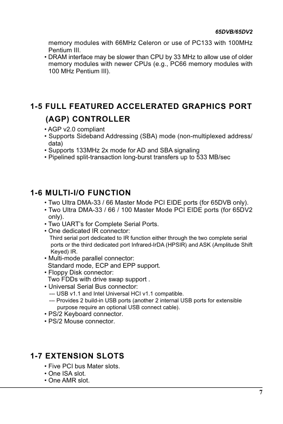
memory modules with 66MHz Celeron or use of PC133 with 100MHz
Pentium III.
• DRAM interface may be slower than CPU by 33 MHz to allow use of older
memory modules with newer CPUs (e.g., PC66 memory modules with
100 MHz Pentium III).
65DVB/65DV2
1-5 FULL FEATURED ACCELERATED GRAPHICS PORT
(AGP) CONTROLLER
• AGP v2.0 compliant
• Supports Sideband Addressing (SBA) mode (non-multiplexed address/
• Supports 133MHz 2x mode for AD and SBA signaling
• Pipelined split-transaction long-burst transfers up to 533 MB/sec
data)
only).
1-6 MULTI-I/O FUNCTION
• Two Ultra DMA-33 / 66 Master Mode PCI EIDE ports (for 65DVB only).
• Two Ultra DMA-33 / 66 / 100 Master Mode PCI EIDE ports (for 65DV2
• Two UART’s for Complete Serial Ports.
• One dedicated IR connector:
Third serial port dedicated to IR function either through the two complete serial
ports or the third dedicated port Infrared-IrDA (HPSIR) and ASK (Amplitude Shift
Keyed) IR.
• Multi-mode parallel connector:
Standard mode, ECP and EPP support.
• Floppy Disk connector:
Two FDDs with drive swap support .
• Universal Serial Bus connector:
--- USB v1.1 and Intel Universal HCI v1.1 compatible.
--- Provides 2 build-in USB ports (another 2 internal USB ports for extensible
purpose require an optional USB connect cable).
• PS/2 Keyboard connector.
• PS/2 Mouse connector.
1-7 EXTENSION SLOTS
• Five PCI bus Mater slots.
• One ISA slot.
• One AMR slot.
7
�
65DVB/65DV2
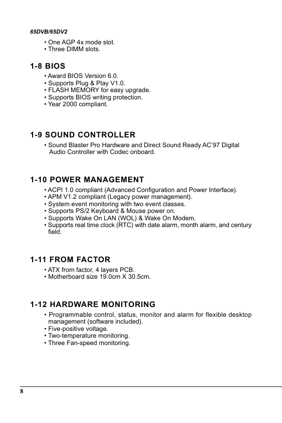
• One AGP 4x mode slot.
• Three DIMM slots.
1-8 BIOS
• Award BIOS Version 6.0.
• Supports Plug & Play V1.0.
• FLASH MEMORY for easy upgrade.
• Supports BIOS writing protection.
• Year 2000 compliant.
1-9 SOUND CONTROLLER
• Sound Blaster Pro Hardware and Direct Sound Ready AC’97 Digital
Audio Controller with Codec onboard.
1-10 POWER MANAGEMENT
• ACPI 1.0 compliant (Advanced Configuration and Power Interface).
• APM V1.2 compliant (Legacy power management).
• System event monitoring with two event classes.
• Supports PS/2 Keyboard & Mouse power on.
• Supports Wake On LAN (WOL) & Wake On Modem.
• Supports real time clock (RTC) with date alarm, month alarm, and century
field.
1-11 FROM FACTOR
• ATX from factor, 4 layers PCB.
• Motherboard size 19.0cm X 30.5cm.
1-12 HARDWARE MONITORING
• Programmable control, status, monitor and alarm for flexible desktop
management (software included).
• Five-positive voltage.
• Two-temperature monitoring.
• Three Fan-speed monitoring.
8
�




 2023年江西萍乡中考道德与法治真题及答案.doc
 2012年重庆南川中考生物真题及答案.doc
 2013年江西师范大学地理学综合及文艺理论基础考研真题.doc
 2020年四川甘孜小升初语文真题及答案I卷.doc
 2020年注册岩土工程师专业基础考试真题及答案.doc
 2023-2024学年福建省厦门市九年级上学期数学月考试题及答案.doc
 2021-2022学年辽宁省沈阳市大东区九年级上学期语文期末试题及答案.doc
 2022-2023学年北京东城区初三第一学期物理期末试卷及答案.doc
 2018上半年江西教师资格初中地理学科知识与教学能力真题及答案.doc
 2012年河北国家公务员申论考试真题及答案-省级.doc
 2020-2021学年江苏省扬州市江都区邵樊片九年级上学期数学第一次质量检测试题及答案.doc
 2022下半年黑龙江教师资格证中学综合素质真题及答案.doc