logo资料库

三星 CLP-680DWXIL+CLP-680ND XIL+维修手册全手册.pdf

第1页 / 共127页
第2页 / 共127页
第3页 / 共127页
第4页 / 共127页
第5页 / 共127页
第6页 / 共127页
第7页 / 共127页
第8页 / 共127页
资料共127页,剩余部分请下载后查看
Color Laser Printer
1. Precautions
1.1. Safety warning
1.2. Caution for safety
1.2.1. Toxic material
1.2.2. Electric shock and fire safety precautions
1.2.3. Handling precautions
1.2.4. Assembly and Disassembly precautions
1.2.5. Disregarding this warning may cause bodily injury
1.3. ESD precautions
2. Product Specification and description
2.1. Product Specification
2.1.1. Product Overview
2.1.2. Specifications
2.1.2.1. General Print Engine
2.1.2.2. Controller and Software
2.1.2.3. Paper Handling
2.1.2.4. Reliability and Service
2.1.2.5. Environment
2.1.2.6. Consumables
2.1.2.7. Maintenance Parts
2.1.2.8. Option
2.1.3. Model Comparison Table
2.2. System Overview
2.2.1. Front View
2.2.2. Rear View
2.2.3. Paper Path
2.2.4. System Layout
2.2.4.1. Feeding Section
2.2.4.2. Transfer Roller
2.2.4.3. Drive Unit
2.2.4.4. Fuser Unit
2.2.4.5. LSU (Laser Scanner Unit)
2.2.4.6. Toner Cartridge
2.2.5. Hardware configuration
2.2.5.1. Main board
2.2.5.2. OPE Controller
2.2.5.3. Wireless LAN board
2.2.5.4. SMPS board
2.2.5.5. HVPS board
2.2.5.6. ITB EEPROM PBA
2.2.5.7. HUB PBA
2.2.5.8. Electrical Parts Location
2.2.6. Engine F/W Control Algorithm
2.2.6.1. Feeding
2.2.6.2. Transfer
2.2.6.3. Fusing
2.2.6.4. LSU
2.2.7. Software Descriptions
2.2.7.1. Software system overview
2.2.7.2. Architecture
2.2.7.3. Data and Control Flow
3. Disassembly and Reassembly
3.1. Precautions when replacing parts
3.1.1. Precautions when assembling and disassembling
3.1.2. Precautions when handling PBA
3.1.3. Releasing Plastic Latches
3.2. Screws used in the printer
3.3. Replacing the maintenance parts
3.3.1. Toner Cartridge
3.3.2. Waste Toner Container
3.3.3. ITB Unit
3.3.4. Fuser Unit
3.3.5. Pick up_Forward_Reverse roller
3.4. Replacing the main SVC parts
3.4.1. Left and Right cover
3.4.2. Top cover
3.4.3. HVPS board
3.4.4. Outer Temperature Sensor
3.4.5. Main Board
3.4.6. SMPS Fan
3.4.7. SMPS board
3.4.8. LSU
3.4.9. Fuser Fan
3.4.10. Main Drive Unit
3.4.11. DRIVE-T1
3.4.12. Fuser Drive Unit
3.4.13. PH (Paper Handling) Drive Unit
3.4.14. Exit Unit
3.4.15. MP Pick-Up Unit
4. Alignment and Troubleshooting
4.1. Alignment and Adjustments
4.1.1. Control panel
4.1.2. Understanding the status LED
4.1.3. Clearing paper jams
4.1.4. Useful menu item for service
4.1.5. Periodic Defective Image
4.1.6. Useful management tools
4.1.6.1. Using Samsung Easy Printer Manager (Windows and Macinto
4.1.6.2. Using Samsung Printer Status (Windows only)
4.1.6.3. Using SyncThru Web Service (SWS)
4.1.7. Updating Firmware
4.1.7.1. Update the firmware by using the USB port
4.1.7.2. Update the firmware by using the network
4.1.8. Tech Mode (Diagnostic Mode)
4.2. Troubleshooting
4.2.1. Procedure of checking the symptoms
4.2.1.1. Basic Check List
4.2.2. Error Code and Troubleshooting
4.2.3. Image quality problems
4.2.4. Other errors
5. System Diagram
5.1. Block Diagram
5.2. Connection Diagram
6. Reference Information
6.1. Tool for Troubleshooting
6.2. Glossary
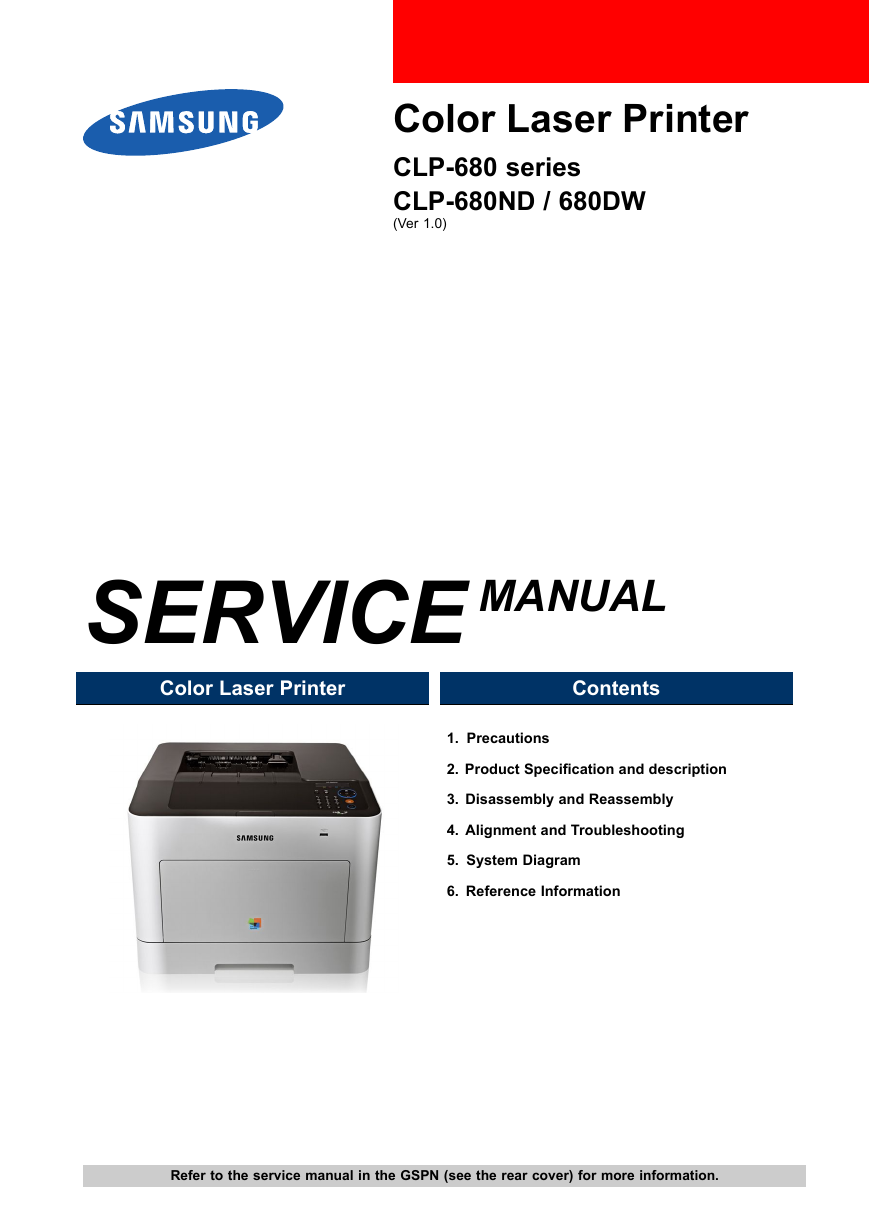
Color Laser Printer CLP-680 series CLP-680ND / 680DW (Ver 1.0) SERVICE MANUAL Color Laser Printer Contents 1. Precautions 2. Product Specification and description 3. Disassembly and Reassembly 4. Alignment and Troubleshooting 5. System Diagram 6. Reference Information Refer to the service manual in the GSPN (see the rear cover) for more information.
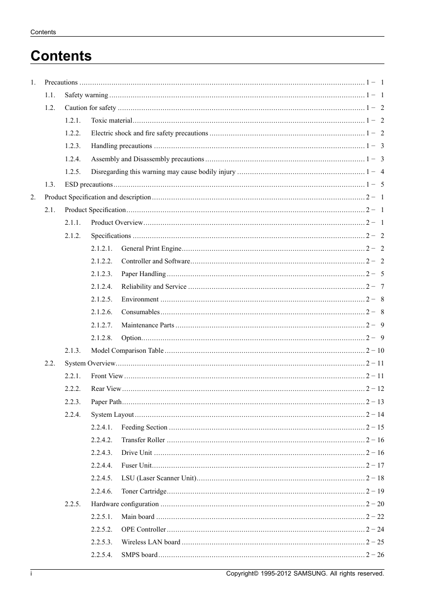
Contents Contents 1. 2. Precautions ...................................................................................................................................... 1 − 1 1.1. Safety warning ........................................................................................................................ 1 − 1 Caution for safety .................................................................................................................... 1 − 2 1.2. 1.2.1. Toxic material............................................................................................................. 1 − 2 Electric shock and fire safety precautions ......................................................................... 1 − 2 1.2.2. Handling precautions ................................................................................................... 1 − 3 1.2.3. 1.2.4. Assembly and Disassembly precautions ........................................................................... 1 − 3 1.2.5. Disregarding this warning may cause bodily injury ............................................................ 1 − 4 1.3. ESD precautions...................................................................................................................... 1 − 5 Product Specification and description .................................................................................................... 2 − 1 Product Specification................................................................................................................ 2 − 1 2.1. Product Overview........................................................................................................ 2 − 1 2.1.1. 2.1.2. Specifications ............................................................................................................. 2 − 2 2.1.2.1. General Print Engine...................................................................................... 2 − 2 2.1.2.2. Controller and Software.................................................................................. 2 − 2 2.1.2.3. Paper Handling ............................................................................................. 2 − 5 2.1.2.4. Reliability and Service ................................................................................... 2 − 7 2.1.2.5. Environment ................................................................................................ 2 − 8 2.1.2.6. Consumables................................................................................................ 2 − 8 2.1.2.7. Maintenance Parts ......................................................................................... 2 − 9 2.1.2.8. Option......................................................................................................... 2 − 9 2.1.3. Model Comparison Table .............................................................................................. 2 − 10 System Overview..................................................................................................................... 2 − 11 2.2.1. Front View ................................................................................................................. 2 − 11 Rear View.................................................................................................................. 2 − 12 2.2.2. Paper Path.................................................................................................................. 2 − 13 2.2.3. 2.2.4. System Layout ............................................................................................................ 2 − 14 Feeding Section ............................................................................................ 2 − 15 2.2.4.1. 2.2.4.2. Transfer Roller ............................................................................................. 2 − 16 2.2.4.3. Drive Unit ................................................................................................... 2 − 16 Fuser Unit.................................................................................................... 2 − 17 2.2.4.4. 2.2.4.5. LSU (Laser Scanner Unit)............................................................................... 2 − 18 2.2.4.6. Toner Cartridge............................................................................................. 2 − 19 Hardware configuration ................................................................................................ 2 − 20 2.2.5.1. Main board .................................................................................................. 2 − 22 2.2.5.2. OPE Controller ............................................................................................. 2 − 24 2.2.5.3. Wireless LAN board ...................................................................................... 2 − 25 2.2.5.4. SMPS board................................................................................................. 2 − 26 2.2.5. 2.2. i Copyright© 1995-2012 SAMSUNG. All rights reserved.
Contents 2.2.6. 2.2.7. 3.1. 3.2. 3.3. 2.2.5.5. HVPS board................................................................................................. 2 − 28 2.2.5.6. ITB EEPROM PBA....................................................................................... 2 − 29 2.2.5.7. HUB PBA ................................................................................................... 2 − 29 2.2.5.8. Electrical Parts Location................................................................................. 2 − 30 Engine F/W Control Algorithm ...................................................................................... 2 − 32 Feeding ....................................................................................................... 2 − 32 2.2.6.1. 2.2.6.2. Transfer....................................................................................................... 2 − 32 Fusing......................................................................................................... 2 − 33 2.2.6.3. 2.2.6.4. LSU............................................................................................................ 2 − 33 Software Descriptions .................................................................................................. 2 − 34 2.2.7.1. Software system overview .............................................................................. 2 − 34 2.2.7.2. Architecture ................................................................................................. 2 − 34 2.2.7.3. Data and Control Flow ................................................................................... 2 − 35 3. Disassembly and Reassembly .............................................................................................................. 3 − 1 Precautions when replacing parts ................................................................................................ 3 − 1 Precautions when assembling and disassembling ............................................................... 3 − 1 3.1.1. 3.1.2. Precautions when handling PBA..................................................................................... 3 − 1 3.1.3. Releasing Plastic Latches .............................................................................................. 3 − 2 Screws used in the printer.......................................................................................................... 3 − 3 Replacing the maintenance parts ................................................................................................. 3 − 5 3.3.1. Toner Cartridge........................................................................................................... 3 − 5 3.3.2. Waste Toner Container ................................................................................................. 3 − 6 3.3.3. ITB Unit.................................................................................................................... 3 − 7 Fuser Unit.................................................................................................................. 3 − 9 3.3.4. 3.3.5. Pick up_Forward_Reverse roller..................................................................................... 3 − 9 Replacing the main SVC parts.................................................................................................... 3 − 10 Left and Right cover .................................................................................................... 3 − 10 3.4.1. Top cover................................................................................................................... 3 − 11 3.4.2. 3.4.3. HVPS board ............................................................................................................... 3 − 12 3.4.4. Outer Temperature Sensor............................................................................................. 3 − 12 3.4.5. Main Board ................................................................................................................ 3 − 13 3.4.6. SMPS Fan.................................................................................................................. 3 − 13 SMPS board ............................................................................................................... 3 − 14 3.4.7. 3.4.8. LSU.......................................................................................................................... 3 − 14 3.4.9. Fuser Fan................................................................................................................... 3 − 15 3.4.10. Main Drive Unit.......................................................................................................... 3 − 15 3.4.11. DRIVE-T1 ................................................................................................................. 3 − 16 3.4.12. Fuser Drive Unit ......................................................................................................... 3 − 16 3.4.13. PH (Paper Handling) Drive Unit..................................................................................... 3 − 17 3.4.14. Exit Unit.................................................................................................................... 3 − 18 3.4. Copyright© 1995-2012 SAMSUNG. All rights reserved. ii
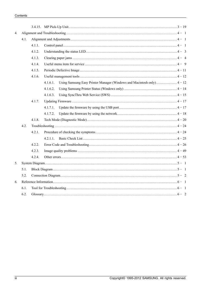
Contents 4.1.1. 4.1.2. 4.1.3. 4.1.4. 4.1.5. 4.1.6. 3.4.15. MP Pick-Up Unit......................................................................................................... 3 − 19 4. Alignment and Troubleshooting ........................................................................................................... 4 − 1 4.1. Alignment and Adjustments....................................................................................................... 4 − 1 Control panel.............................................................................................................. 4 − 1 Understanding the status LED........................................................................................ 4 − 3 Clearing paper jams ..................................................................................................... 4 − 4 Useful menu item for service ......................................................................................... 4 − 9 Periodic Defective Image .............................................................................................. 4 − 11 Useful management tools .............................................................................................. 4 − 12 4.1.6.1. Using Samsung Easy Printer Manager (Windows and Macintosh only).................... 4 − 12 4.1.6.2. Using Samsung Printer Status (Windows only) ................................................... 4 − 14 4.1.6.3. Using SyncThru Web Service (SWS) ................................................................ 4 − 15 Updating Firmware...................................................................................................... 4 − 17 4.1.7.1. Update the firmware by using the USB port........................................................ 4 − 17 4.1.7.2. Update the firmware by using the network.......................................................... 4 − 18 4.1.8. Tech Mode (Diagnostic Mode)....................................................................................... 4 − 20 Troubleshooting ...................................................................................................................... 4 − 24 4.2.1. Procedure of checking the symptoms............................................................................... 4 − 24 4.2.1.1. Basic Check List ........................................................................................... 4 − 25 Error Code and Troubleshooting..................................................................................... 4 − 26 Image quality problems ................................................................................................ 4 − 49 Other errors................................................................................................................ 4 − 53 System Diagram................................................................................................................................ 5 − 1 Block Diagram........................................................................................................................ 5 − 1 5.1. 5.2. Connection Diagram................................................................................................................. 5 − 2 6. Reference Information........................................................................................................................ 6 − 1 6.1. Tool for Troubleshooting........................................................................................................... 6 − 1 6.2. Glossary................................................................................................................................. 6 − 2 4.2. 4.1.7. 4.2.2. 4.2.3. 4.2.4. 5. iii Copyright© 1995-2012 SAMSUNG. All rights reserved.
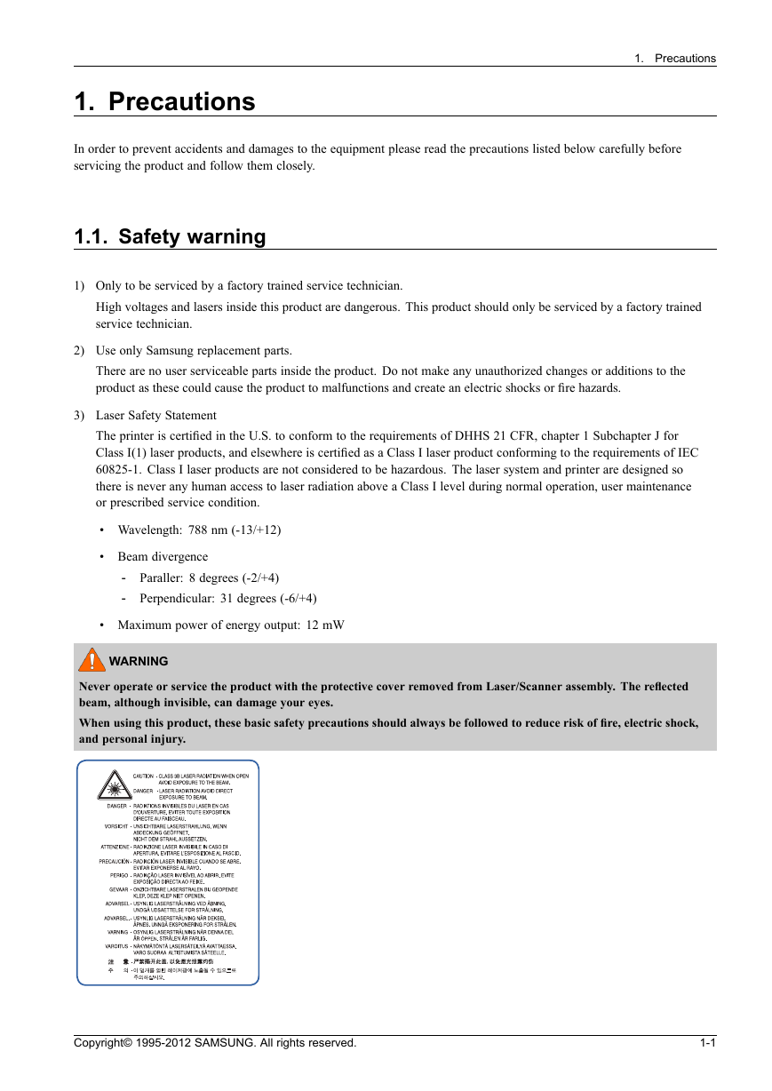
1. Precautions In order to prevent accidents and damages to the equipment please read the precautions listed below carefully before servicing the product and follow them closely. 1. Precautions 1.1. Safety warning 1) Only to be serviced by a factory trained service technician. High voltages and lasers inside this product are dangerous. This product should only be serviced by a factory trained service technician. 2) Use only Samsung replacement parts. There are no user serviceable parts inside the product. Do not make any unauthorized changes or additions to the product as these could cause the product to malfunctions and create an electric shocks or fire hazards. 3) Laser Safety Statement The printer is certified in the U.S. to conform to the requirements of DHHS 21 CFR, chapter 1 Subchapter J for Class I(1) laser products, and elsewhere is certified as a Class I laser product conforming to the requirements of IEC 60825-1. Class I laser products are not considered to be hazardous. The laser system and printer are designed so there is never any human access to laser radiation above a Class I level during normal operation, user maintenance or prescribed service condition. • Wavelength: 788 nm (-13/+12) • Beam divergence - Paraller: 8 degrees (-2/+4) - Perpendicular: 31 degrees (-6/+4) • Maximum power of energy output: 12 mW WARNING Never operate or service the product with the protective cover removed from Laser/Scanner assembly. The reflected beam, although invisible, can damage your eyes. When using this product, these basic safety precautions should always be followed to reduce risk of fire, electric shock, and personal injury. Copyright© 1995-2012 SAMSUNG. All rights reserved. 1-1
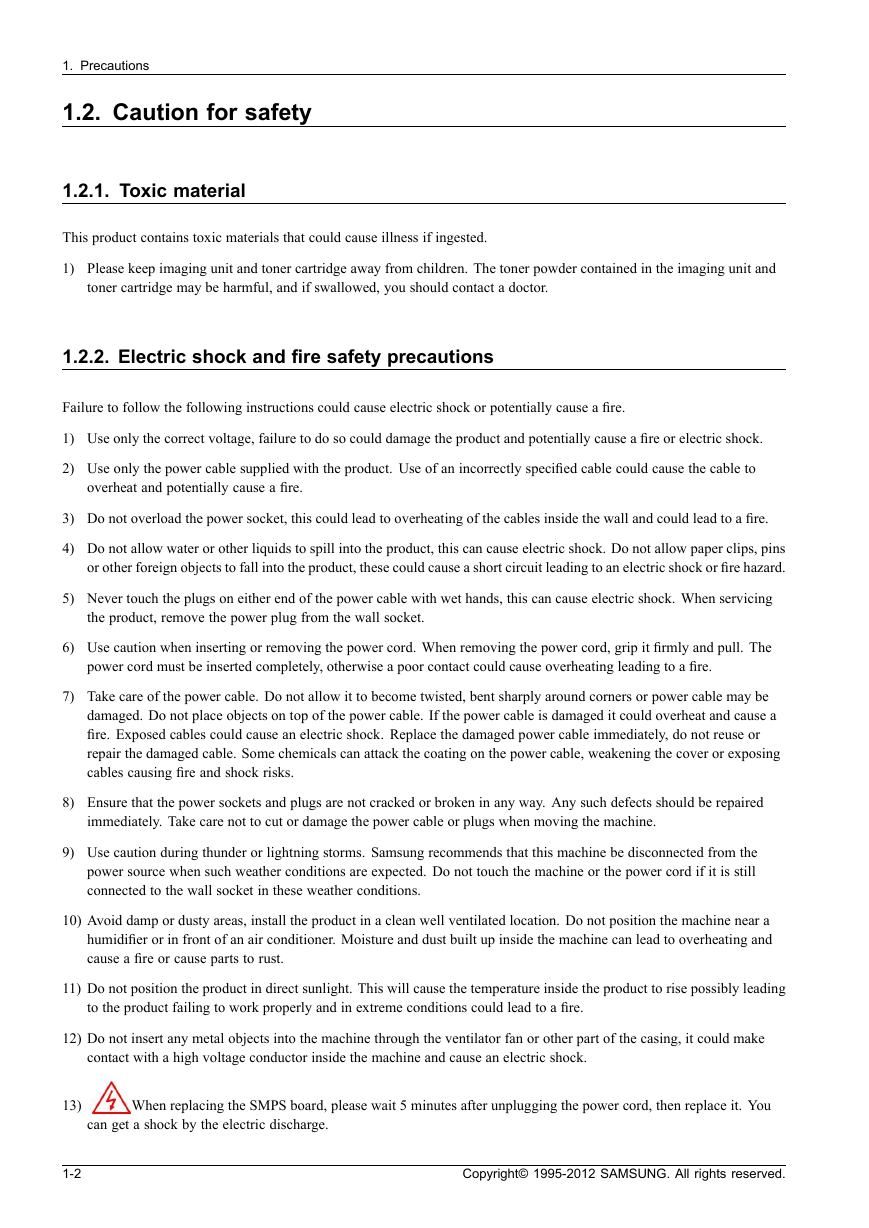
1. Precautions 1.2. Caution for safety 1.2.1. Toxic material This product contains toxic materials that could cause illness if ingested. 1) Please keep imaging unit and toner cartridge away from children. The toner powder contained in the imaging unit and toner cartridge may be harmful, and if swallowed, you should contact a doctor. 1.2.2. Electric shock and fire safety precautions Failure to follow the following instructions could cause electric shock or potentially cause a fire. 1) Use only the correct voltage, failure to do so could damage the product and potentially cause a fire or electric shock. 2) Use only the power cable supplied with the product. Use of an incorrectly specified cable could cause the cable to overheat and potentially cause a fire. 3) Do not overload the power socket, this could lead to overheating of the cables inside the wall and could lead to a fire. 4) Do not allow water or other liquids to spill into the product, this can cause electric shock. Do not allow paper clips, pins or other foreign objects to fall into the product, these could cause a short circuit leading to an electric shock or fire hazard. 5) Never touch the plugs on either end of the power cable with wet hands, this can cause electric shock. When servicing the product, remove the power plug from the wall socket. 6) Use caution when inserting or removing the power cord. When removing the power cord, grip it firmly and pull. The power cord must be inserted completely, otherwise a poor contact could cause overheating leading to a fire. 7) Take care of the power cable. Do not allow it to become twisted, bent sharply around corners or power cable may be damaged. Do not place objects on top of the power cable. If the power cable is damaged it could overheat and cause a fire. Exposed cables could cause an electric shock. Replace the damaged power cable immediately, do not reuse or repair the damaged cable. Some chemicals can attack the coating on the power cable, weakening the cover or exposing cables causing fire and shock risks. 8) Ensure that the power sockets and plugs are not cracked or broken in any way. Any such defects should be repaired immediately. Take care not to cut or damage the power cable or plugs when moving the machine. 9) Use caution during thunder or lightning storms. Samsung recommends that this machine be disconnected from the power source when such weather conditions are expected. Do not touch the machine or the power cord if it is still connected to the wall socket in these weather conditions. 10) Avoid damp or dusty areas, install the product in a clean well ventilated location. Do not position the machine near a humidifier or in front of an air conditioner. Moisture and dust built up inside the machine can lead to overheating and cause a fire or cause parts to rust. 11) Do not position the product in direct sunlight. This will cause the temperature inside the product to rise possibly leading to the product failing to work properly and in extreme conditions could lead to a fire. 12) Do not insert any metal objects into the machine through the ventilator fan or other part of the casing, it could make contact with a high voltage conductor inside the machine and cause an electric shock. 13) 1-2 When replacing the SMPS board, please wait 5 minutes after unplugging the power cord, then replace it. You can get a shock by the electric discharge. Copyright© 1995-2012 SAMSUNG. All rights reserved.
1. Precautions 1.2.3. Handling precautions The following instructions are for your own personal safety to avoid injury and so as not to damage the product. 1) Ensure the product is installed on a level surface, capable of supporting its weight. Failure to do so could cause the product to tip or fall. 2) The product contains many rollers, gears and fans. Take great care to ensure that you do not catch your fingers, hair or clothing in any of these rotating devices. 3) Do not place any small metal objects, containers of water, chemicals or other liquids close to the product which if spilled could get into the machine and cause damage or a shock or fire hazard. 4) Do not install the machine in areas with high dust or moisture levels, beside on open window or close to a humidifier or heater. Damage could be caused to the product in such areas. 5) Do not place candles, burning cigarettes, etc on the product, These could cause a fire. 1.2.4. Assembly and Disassembly precautions 1) Replace parts carefully and always use Samsung parts. Take care to note the exact location of parts and also cable routing before dismantling any part of the machine. Ensure all parts and cables are replaced correctly. Please carry out the following procedures before dismantling the product or replacing any parts. 2) Ensure that power is disconnected before servicing or replacing any electrical parts. 3) Disconnect interface cables and power cables. 4) Only use approved spare parts. Ensure that part number, product name, any voltage, current or temperature rating are correct. 5) When removing or re-fitting any parts do not use excessive force, especially when fitting screws into plastic. 6) Take care not to drop any small parts into the machine. 7) Handling of the OPC Drum • The OPC Drum can be irreparably damaged if it exposed to light. Take care not to expose the OPC Drum either to direct sunlight or to fluorescent or incandescent room lighting. Exposure for as little as 5 minutes can damage the surface of the photoconductive properties and will result in print quality degradation. Take extra care when servicing the product. Remove the OPC Drum and store it in a black bag or other lightproof container. Take care when working with the Covers (especially the top cover) open as light is admitted to the OPC area and can damage the OPC Drum. • Take care not to scratch the green surface of OPC Drum Unit. If the green surface of the Drum Cartridge is scratched or touched the print quality will be compromised. Copyright© 1995-2012 SAMSUNG. All rights reserved. 1-3
1. Precautions 1.2.5. Disregarding this warning may cause bodily injury 1) Be careful with the high temperature part. The fuser unit works at a high temperature. Use caution when working on the printer. Wait for the fuser unit to cool down before disassembly. 2) Do not put fingers or hair into the rotating parts. When operating a printer, do not put hand or hair into the rotating parts (Paper feeding entrance, motor, fan, etc.). If do, you can get harm. 3) When you move the printer, use safe lifting and handling techniques. This printer is heavy. Use the lifting handles located on each side of the machine. Back injury could be caused if you do not lift carefully. 4) Ensure the printer is installed safely. Ensure the printer is installed on a level surface, capable of supporting its weight. Failure to do so could cause the printer to tip or fall possibly causing personal injury or damaging the printer. 5) Do not install the printer on a sloping or unstable surface. After installation, double check that the printer is stable. 1-4 Copyright© 1995-2012 SAMSUNG. All rights reserved.
分享到:
收藏