I Overview
Preface
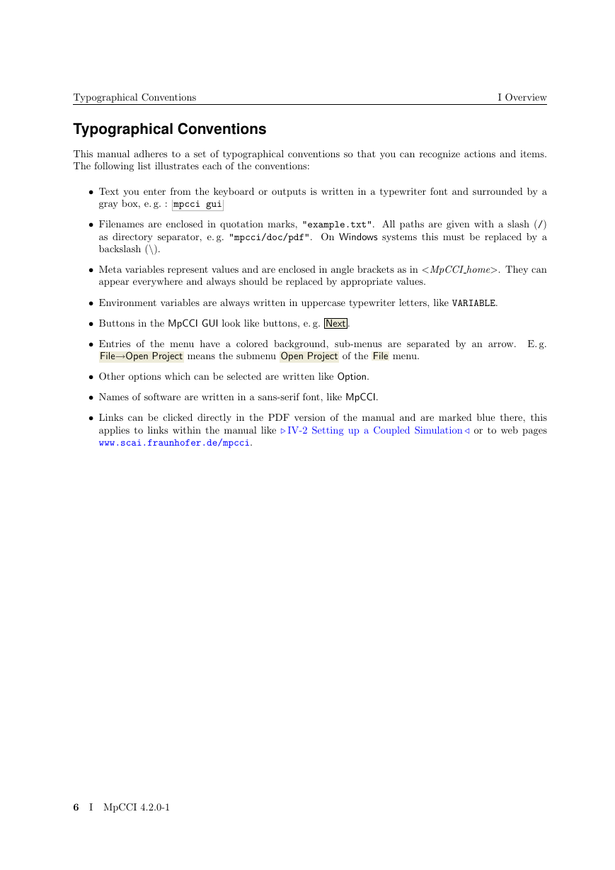
Typographical Conventions
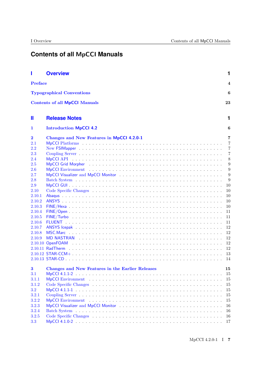
Contents of all MpCCI Manuals
II Release Notes
1 Introduction MpCCI 4.2
2 Changes and New Features in MpCCI 4.2.0-1
2.1 MpCCI Platforms
2.2 New FSIMapper
2.3 Coupling Server
2.4 MpCCI API
2.5 MpCCI Grid Morpher
2.6 MpCCI Environment
2.7 MpCCI Visualizer and MpCCI Monitor
2.8 Batch System
2.9 MpCCI GUI
2.10 Code Specific Changes
2.10.1 Abaqus
2.10.2 ANSYS
2.10.3 FINE/Hexa
2.10.4 FINE/Open
2.10.5 FINE/Turbo
2.10.6 FLUENT
2.10.7 ANSYS Icepak
2.10.8 MSC.Marc
2.10.9 MD NASTRAN
2.10.10 OpenFOAM
2.10.11 RadTherm
2.10.12 STAR-CCM+
2.10.13 STAR-CD
3 Changes and New Features in the Earlier Releases
3.1 MpCCI 4.1.1-2
3.1.1 MpCCI Environment
3.1.2 Code Specific Changes
3.2 MpCCI 4.1.1-1
3.2.1 Coupling Server
3.2.2 MpCCI Environment
3.2.3 MpCCI Visualizer and MpCCI Monitor
3.2.4 Batch System
3.2.5 Code Specific Changes
3.3 MpCCI 4.1.0-2
3.3.1 Coupling Server
3.3.2 MpCCI Environment
3.3.3 MpCCI GUI
3.3.4 Code Specific Changes
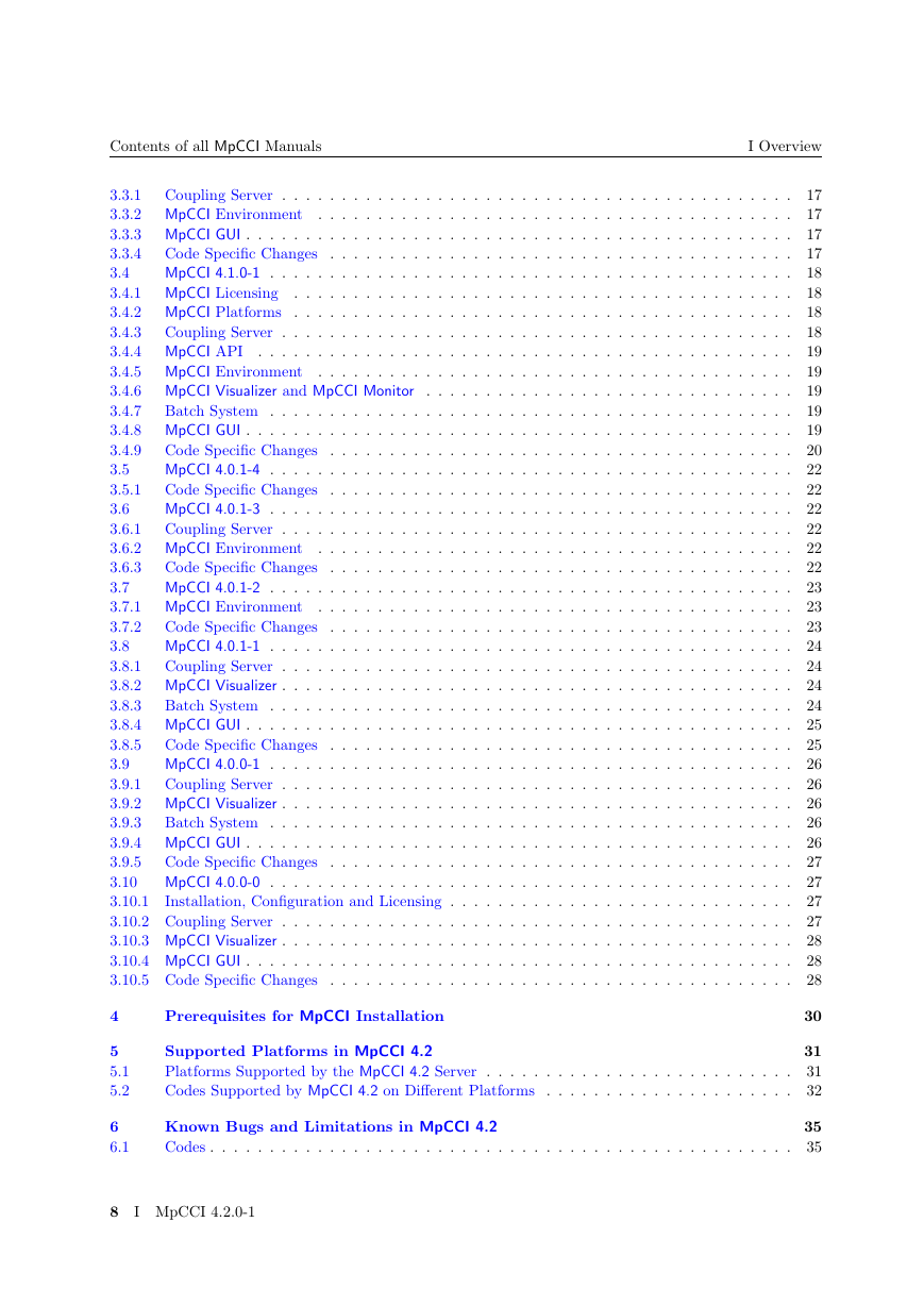
3.4 MpCCI 4.1.0-1
3.4.1 MpCCI Licensing
3.4.2 MpCCI Platforms
3.4.3 Coupling Server
3.4.4 MpCCI API
3.4.5 MpCCI Environment
3.4.6 MpCCI Visualizer and MpCCI Monitor
3.4.7 Batch System
3.4.8 MpCCI GUI
3.4.9 Code Specific Changes
3.5 MpCCI 4.0.1-4
3.5.1 Code Specific Changes
3.6 MpCCI 4.0.1-3
3.6.1 Coupling Server
3.6.2 MpCCI Environment
3.6.3 Code Specific Changes
3.7 MpCCI 4.0.1-2
3.7.1 MpCCI Environment
3.7.2 Code Specific Changes
3.8 MpCCI 4.0.1-1
3.8.1 Coupling Server
3.8.2 MpCCI Visualizer
3.8.3 Batch System
3.8.4 MpCCI GUI
3.8.5 Code Specific Changes
3.9 MpCCI 4.0.0-1
3.9.1 Coupling Server
3.9.2 MpCCI Visualizer
3.9.3 Batch System
3.9.4 MpCCI GUI
3.9.5 Code Specific Changes
3.10 MpCCI 4.0.0-0
3.10.1 Installation, Configuration and Licensing
3.10.2 Coupling Server
3.10.3 MpCCI Visualizer
3.10.4 MpCCI GUI
3.10.5 Code Specific Changes
4 Prerequisites for MpCCI Installation
5 Supported Platforms in MpCCI 4.2
5.1 Platforms Supported by the MpCCI 4.2 Server
5.2 Codes Supported by MpCCI 4.2 on Different Platforms
6 Known Bugs and Limitations in MpCCI 4.2
6.1 Codes
III Installation Guide
1 Installation Overview
2 Before the Installation
2.1 Downloading MpCCI
2.2 Where to Install
2.3 The Perl Interpreter
2.4 The Java Runtime Environment
2.5 OpenSSH for Microsoft Windows
2.6 MpCCI-RSH for Microsoft Windows
3 Installation of the MpCCI Software
3.1 Multi-platform for UNIX, Linux and Microsoft Windows
3.2 Local Microsoft Windows Installation with the MSI
4 Immediately After the Installation - Quick Installation Tests without a License
4.1 Your Home Directory under Microsoft Windows
4.2 Testing the MpCCI Working Environment and Perl
4.3 Testing whether MpCCI Finds Your Simulation Codes
5 Licensing
5.1 Request for a License File
5.2 Installing and Activating a License
5.2.1 Configure a License Manager as UNIX service
5.2.2 Configure a License Manager as Windows service
5.3 Defining the License Server
5.4 Multiple License Servers
5.5 Testing the License Server
6 Configuring the MpCCI Users Environment
6.1 Accessing Remote Hosts
6.2 Configuring MpCCI via Environment Variables
7 Testing the MpCCI Installation and Communication
8 Troubleshooting
8.1 Secure shell in general
8.2 OpenSSH under Microsoft Windows
8.3 rsh, rcp and rlogin under Microsoft Windows
9 Installing Perl
10 Installing Java
IV Getting Started
1 Multi-Physics Computation with MpCCI
1.1 Multi-Physics
1.2 Solution of Coupled Problems
1.3 Code Coupling with MpCCI
2 Setting up a Coupled Simulation
2.1 A Simple Example
2.2 Model Preparation
2.2.1 CFD Model
2.2.2 FE Model
2.3 Starting the MpCCI GUI
2.4 Models Step -- Choosing Codes and Model Files
2.5 Coupling Step -- Definition of Coupling Regions and Quantities
2.5.1 Define Coupling Regions
2.5.2 Select the Components for each Interconnected Code
2.5.3 Specify the Quantities which will be Exchanged
2.6 Monitors Step -- Definition of Quantities for Monitoring
2.7 Edit Step -- Further Coupling Options
2.8 Go Step -- Starting Server and Codes
2.8.1 Configuring the Initial Exchange Mode
2.8.2 Setting Option Parameters
2.8.3 Starting the Coupled Simulation
2.8.4 Interrupting the Computation
3 Checking the Results
3.1 The MpCCI Visualizer
3.2 Post-Processing
V User Manual
1 Introduction
1.1 Basic Structure of MpCCI
2 The MpCCI Software Package
2.1 Introduction
2.2 The MpCCI Home Directory
2.3 Environment and Environment Variables
2.3.1 MPCCI_ARCH - Architecture Tokens
2.3.2 MPCCI_DEBUG - for Debugging
2.3.3 MPCCI_TINFO
2.4 MpCCI Project and Output Files
2.4.1 MpCCI Project Files
2.4.2 MpCCI Server Input Files
2.4.3 Log Files
2.4.4 Tracefile
2.5 The MpCCI Resource Directory
2.6 Temporary Files
2.7 Third Party Software Used by MpCCI
2.7.1 Perl
2.7.2 Java
2.7.3 Remote Shell and Remote Copy
3 Code Coupling
3.1 Multi-Physics
3.1.1 Physical Domains
3.1.2 Coupling Types
3.2 Mesh Checks
3.2.1 Mesh Motion Checks
3.2.2 Bounding Box Checks
3.3 Data Exchange
3.3.1 Association
3.3.2 Interpolation
3.4 Coupling Algorithms
3.4.1 Course of the Coupling Process
3.4.2 Stationary Problems
3.4.3 Transient Problems
3.4.4 Exchange of Time Step Size
3.4.5 Subcycling
3.4.6 Restarting a Coupled Simulation
3.5 Running MpCCI in a Network
3.5.1 Client-Server Structure of MpCCI
3.5.2 Hostlist Files
3.5.3 Remote Shell and Remote Copy
3.6 Coupled Analysis in Batch Mode
3.6.1 General Approach
3.6.2 Job Scheduler Environment
4 Graphical User Interface
4.1 Starting and Exiting MpCCI GUI
4.1.1 Starting MpCCI GUI
4.1.2 Exiting MpCCI GUI
4.2 MpCCI GUI Menus
4.2.1 File Menu
4.2.2 Batch Menu
4.2.3 License Menu
4.2.4 Tools Menu
4.2.5 Preferences Menu
4.2.6 Codes Menu
4.2.7 Help Menu
4.3 Models Step
4.3.1 Code Parameters
4.3.2 Requirements
4.4 Coupling Step
4.4.1 Coupling components with different dimensions
4.4.2 Copying Components
4.4.3 Editing Component Properties
4.4.4 Generate Regions
4.4.5 Options Part
4.4.6 Global Quantity Properties
4.4.7 Specific Quantity Properties for sender, receiver
4.4.8 Quantity Sender
4.4.9 Predefined Sets
4.4.10 Requirements
4.5 Monitors Step
4.6 Edit Step
4.6.1 Monitor
4.6.2 Mesh Motion
4.6.3 Overlap Check
4.6.4 Relation Search
4.6.5 Output
4.7 Go Step
4.7.1 Configuring the MpCCI Coupling Server
4.8 Remote File Browser
4.8.1 File Browser Handling
4.8.2 How to mount a new file system
5 Command Line Interface
5.1 Using the Command Line Interface
5.2 Overview of All Subcommands
5.3 Starting MpCCI
5.3.1 mpcci fsimapper
5.3.2 mpcci gui
5.3.3 mpcci morpher
5.3.4 mpcci observe
5.3.5 mpcci pm
5.3.6 mpcci visualize
5.3.7 mpcci monitor
5.3.8 mpcci ccvxcat
5.3.9 mpcci xterm
5.4 Information and Environment
5.4.1 mpcci arch
5.4.2 mpcci doc
5.4.3 mpcci info
5.4.4 mpcci env
5.4.5 mpcci home
5.4.6 mpcci where
5.5 Installation and Licensing
5.5.1 mpcci license
5.5.2 mpcci list
5.5.3 mpcci lmutil
5.5.4 mpcci ssh
5.5.5 mpcci test
5.5.6 mpcci update
5.6 Job Control
5.6.1 mpcci backup
5.6.2 mpcci batch
5.6.3 mpcci batch LSF
5.6.4 mpcci batch PBS
5.6.5 mpcci batch N1GE
5.6.6 mpcci batch LoadLeveler
5.6.7 mpcci batch GLOBUS
5.6.8 mpcci clean
5.6.9 mpcci kill
5.6.10 mpcci ps
5.6.11 mpcci ptoj
5.6.12 mpcci server
5.6.13 mpcci top
6 MpCCI Visualizer
6.1 Using the MpCCI Visualizer
6.1.1 Data Flow
6.1.2 Supported Platforms
6.1.3 Starting the Monitor
6.1.4 Starting the Visualizer
6.2 MpCCI Visualizer for .ccvx and online monitoring
6.2.1 Introduction
6.2.2 Main Window
6.2.3 Menus and Toolbars
6.2.4 Panels
6.2.5 Viewport Area
6.2.6 Preferences Dialog
6.2.7 Error Dialog
6.2.8 Command Line Parameters
6.3 Frequently Asked Questions
7 MpCCI Grid Morpher
7.1 Using the MpCCI Grid Morpher
7.1.1 Options description
8 MpCCI Project Manager
VI Codes Manual
1 Overview
1.1 Common MpCCI Subcommands for Simulation Codes
1.2 Unit Systems
2 Abaqus
2.1 Quick Information
2.1.1 Supported Coupling Schemes
2.1.2 Supported Platforms and Versions
2.1.3 References
2.1.4 Adapter Description
2.1.5 Prerequisites for a coupled simulation
2.2 Coupling Process
2.2.1 Model Preparation
2.2.2 Restart
2.2.3 Models Step
2.2.4 Coupling Step
2.2.5 Go Step
2.2.6 Running the Computation
2.2.7 Post-Processing
2.3 Code-Specific MpCCI Commands
2.4 Code Adapter Reference
2.4.1 Patched Input File
2.5 Co-Simulation Restart
3 ANSYS
3.1 Quick Information
3.1.1 Supported Coupling Schemes
3.1.2 Supported Platforms and Versions
3.1.3 References
3.1.4 Adapter Description
3.1.5 Prerequisites for a coupled simulation
3.1.6 Supported ANSYS product variable
3.2 Coupling Process
3.2.1 Model Preparation
3.2.2 APDL Script
3.2.3 Models Step
3.2.4 Coupling Step
3.2.5 Go Step
3.2.6 Running the Computation
3.3 Code-Specific MpCCI Commands
3.4 Code Adapter Reference
3.5 Frequently Asked Questions
4 ANSYS Icepak
4.1 Quick Information
4.1.1 Supported Platforms and Versions
4.1.2 Supported Quantities
4.2 Code-Specific MpCCI Commands
5 FINE/Hexa
5.1 Quick Information
5.1.1 Supported Coupling Schemes
5.1.2 Supported Platforms and Versions
5.1.3 References
5.1.4 Adapter Description
5.1.5 Prerequisites for a coupled simulation
5.2 Coupling Process
5.3 Code-Specific MpCCI Commands
5.4 Code Adapter Reference
5.5 Limitations
6 FINE/Open
6.1 Quick Information
6.1.1 Supported Coupling Schemes
6.1.2 Supported Platforms and Versions
6.1.3 References
6.1.4 Adapter Description
6.1.5 Prerequisites for a coupled simulation
6.2 Coupling Process
6.2.1 Model Preparation
6.2.2 Models Step
6.2.3 Coupling Step
6.2.4 Go Step
6.2.5 Running the Computation
6.2.6 Post-Processing
6.3 Code-Specific MpCCI Commands
6.4 Code Adapter Reference
6.5 Limitations
7 FINE/Turbo
7.1 Quick Information
7.1.1 Supported Coupling Schemes
7.1.2 Supported Platforms and Versions
7.1.3 References
7.1.4 Adapter Description
7.1.5 Prerequisites for a coupled simulation
7.2 Coupling Process
7.2.1 Model Preparation
7.2.2 Model Preparation within FINE/Turbo GUI
7.2.3 Models Step
7.2.4 Coupling Step
7.2.5 Go Step
7.2.6 Running the Computation
7.2.7 Post-Processing
7.3 Code-Specific MpCCI Commands
8 Flowmaster
8.1 Quick Information
8.1.1 Supported Coupling Schemes
8.1.2 Supported Platforms and Versions
8.1.3 References
8.1.4 Adapter Description
8.1.5 Prerequisites for a coupled simulation
8.2 Coupling Process
8.2.1 Model Preparation
8.2.2 Models Step
8.2.3 Coupling Step
8.2.4 Go Step
8.3 Code-Specific MpCCI Commands
8.4 Code Adapter Description
8.5 Trouble shooting, open issues and known bugs
9 FLUENT
9.1 Quick Information
9.1.1 Supported Coupling Schemes
9.1.2 Supported Platforms and Versions
9.1.3 References
9.1.4 Adapter Description
9.1.5 Prerequisites for a coupled simulation
9.2 Coupling Process
9.2.1 Model Preparation
9.2.2 Models Step
9.2.3 Coupling Step
9.2.4 Go Step
9.2.5 Running the Computation
9.3 Code-Specific MpCCI Commands
9.4 Code Adapter Reference
9.4.1 The MpCCI UDF Library
9.4.2 UDF-Hooks
9.5 Trouble shooting, open issues and known bugs
9.6 Frequently Asked Questions
10 FLUX
10.1 Quick Information
10.1.1 Supported Coupling Schemes
10.1.2 Supported Platforms and Versions
10.1.3 References
10.1.4 Adapter Description
10.1.5 Prerequisites for a coupled simulation
10.2 Coupling Process
10.2.1 Model Preparation
10.2.2 pyFlux script
10.2.3 Models Step
10.2.4 Coupling Step
10.2.5 Go Step
10.3 Code-Specific MpCCI Commands
10.4 Code Adapter Description
11 MD NASTRAN
11.1 Quick Information
11.1.1 Supported Coupling Schemes
11.1.2 Supported Platforms and Versions
11.1.3 Adapter Description
11.1.4 Prerequisites for a coupled simulation
11.2 Coupling Process
11.2.1 Model Preparation
11.2.2 Models Step
11.2.3 Coupling Step
11.2.4 Go Step
11.2.5 Running the Computation
11.2.6 Post-Processing
11.3 Code-Specific MpCCI Commands
11.4 Code Adapter Reference
11.5 Trouble shooting, open issues and known bugs
12 MSC.Marc
12.1 Quick Information
12.1.1 Supported Coupling Schemes
12.1.2 Supported Platforms and Versions
12.1.3 References
12.1.4 Adapter Description
12.1.5 Prerequisites for a coupled simulation
12.2 Coupling Process
12.2.1 Model Preparation
12.2.2 Models Step
12.2.3 Coupling Step
12.2.4 Go Step
12.2.5 Running the Computation
12.2.6 Post-Processing
12.3 Code-Specific MpCCI Commands
13 OpenFOAM
13.1 Quick Information
13.1.1 Supported Coupling Schemes
13.1.2 Supported Platforms and Versions
13.1.3 References
13.1.4 Adapter Description
13.1.5 Prerequisites for a coupled simulation
13.2 Coupling Process
13.2.1 Model Preparation
13.2.2 Models Step
13.2.3 Coupling Step
13.2.4 Go Step
13.2.5 Running the Computation
13.2.6 Post-Processing
13.3 Grid Morphing
13.3.1 MpCCI Grid Morpher
13.3.2 OpenFOAM Grid Morpher
13.4 Code-Specific MpCCI Commands
13.5 Code Adapter Reference
14 RadTherm
14.1 Quick Information
14.1.1 Supported Coupling Schemes
14.1.2 Supported Platforms and Versions
14.1.3 References
14.1.4 Adapter Description
14.1.5 Prerequisites for a coupled simulation
14.2 Coupling Process
14.2.1 Model Preparation
14.2.2 Models Step
14.2.3 Coupling Step
14.2.4 Go Step
14.2.5 Running the Computation
14.2.6 Post-Processing
14.3 Code-Specific MpCCI Commands
15 STAR-CCM+
15.1 Quick Information
15.1.1 Supported Coupling Schemes
15.1.2 Supported Platforms and Versions
15.1.3 References
15.1.4 Adapter Description
15.1.5 Prerequisites for a coupled simulation
15.2 Coupling Process
15.2.1 Model Preparation
15.2.2 Models Step
15.2.3 Coupling Step
15.2.4 Go Step
15.2.5 Running the Computation
15.2.6 Post-Processing
15.3 Code-Specific MpCCI Commands
15.4 Grid Morphing
15.5 Code Adapter Reference
15.5.1 Java Macro Script
15.6 Trouble shooting, open issues and known bugs
16 STAR-CD
16.1 Quick Information
16.1.1 Supported Coupling Schemes
16.1.2 Supported Platforms and Versions
16.1.3 References
16.1.4 Adapter Description
16.1.5 Prerequisites for a coupled simulation
16.2 Coupling Process
16.2.1 Model Preparation
16.2.2 Models Step
16.2.3 Coupling Step
16.2.4 Go Step
16.2.5 Running the Computation
16.2.6 Post-Processing
16.3 Code-Specific MpCCI Commands
16.4 Grid Morphing
16.4.1 MpCCI Grid Morpher
16.4.2 Restart with MpCCI Grid Morpher
16.4.3 pro-STAR Grid Morpher
16.5 Code Adapter Reference
16.5.1 STAR-CD 4.0x
16.5.2 Automatic model preparation STAR-CD 4.0x
16.6 Trouble shooting, open issues and known bugs
VII Tutorial
1 Introduction
2 Vortex-Induced Vibration of a Thin-Walled Structure
2.1 Problem Description
2.2 Model Preparation
2.2.1 Fluid Model
2.2.2 Solid Model
2.3 Models Step
2.4 Coupling Step
2.5 Monitors Step
2.6 Edit Step
2.7 Go Step
2.8 Running the Computation
2.9 Discussion of Results
3 Elastic Flap in a Duct
3.1 Problem Description
3.2 Model Preparation
3.2.1 Solid Model
3.2.2 Fluid Model
3.3 Models Step
3.4 Coupling Step
3.5 Monitors Step
3.6 Edit Step
3.7 Go Step
3.8 Running the Computation
3.8.1 Starting the Simulation
3.8.2 End of the Simulation
3.9 Discussion of Results
4 Exhaust Manifold
4.1 Problem Description
4.2 Model Preparation
4.2.1 Solid Model
4.2.2 Fluid Model
4.2.3 Uncoupled Flow Simulation
4.2.4 Prepare Models for Coupled Simulation
4.3 Models Step
4.4 Coupling Step
4.5 Monitors Step
4.6 Edit Step
4.7 Go Step
4.8 Running the Computation
4.9 Post-processing
5 Busbar System
5.1 Problem Description
5.2 Model Preparation
5.2.1 Fluid Model
5.2.2 Electromagnetic Model
5.3 Models Step
5.4 Coupling Step
5.5 Monitors Step
5.6 Edit Step
5.7 Go Step
5.8 Running the Computation
5.9 Discussion of Results
6 Pipe Nozzle
6.1 Problem Description
6.2 Model Preparation
6.2.1 Fluid Model
6.2.2 Solid Model
6.3 Models Step
6.4 Coupling Step
6.5 Monitors Step
6.6 Edit Step
6.7 Go Step
6.8 Running the Computation
6.9 Discussion of Results
7 Cube in a Duct Heater
7.1 Problem Description
7.2 Model Preparation
7.2.1 Radiation Model
7.2.2 Fluid Model
7.3 Models Step
7.4 Coupling Step
7.5 Monitors Step
7.6 Edit Step
7.7 Go Step
7.8 Running the Computation
7.8.1 Starting the Simulation
7.8.2 End of the Simulation
7.9 Discussion of Results
8 Y-Junction
8.1 Problem Description
8.2 Model Preparation
8.2.1 Network Model
8.2.2 Fluid Model
8.3 Models Step
8.4 Coupling Step
8.5 Monitors Step
8.6 Edit Step
8.7 Go Step
8.8 Running the Computation
8.8.1 Starting the Simulation
8.9 Discussion of Results
VIII Programmers Guide
1 Introduction
2 MpCCI API
2.1 Code Integration and Simulation Code Requirements
2.1.1 Data Exchange and Data Access
2.1.2 MpCCI Interface for Code Integration
2.2 Code Integration with the MpCCI API Kit
2.2.1 A Simple Example
2.2.2 Step-by-Step Procedure for Code Integration
2.2.3 Code Coupling with the Example
2.3 Code Configuration Directory
2.4 MpCCI GUI Configuration File gui.xcf
2.4.1 Code Information:
2.4.2 Codes Menu:
2.4.3 Models Step:
2.4.4 Component Types:
2.4.5 List of quantities:
2.4.6 Go Step:
2.4.7 Environments for Scanner, Starter, Stopper and Killer
2.4.8 General MpCCI GUI Elements
2.4.9 Testing gui.xcf
2.5 Perl Scripts
2.5.1 Using Information from gui.xcf in Scripts
2.5.2 Scanner.pm
2.5.3 Starter.pm
2.5.4 Stopper.pm
2.5.5 Info.pm
2.5.6 Subcmd.pm
2.5.7 Testing the Perl Scripts
2.6 MpCCI Adapter Implementation
2.6.1 How to Initialize the Code?
2.6.2 How to Define the Mesh?
2.6.3 How to Transfer Data?
2.6.4 How to Terminate the Coupling?
2.6.5 How to Notify a Remeshing?
2.7 MpCCI Coupling Manager Functions
2.7.1 Definition of Output Functions: umpcci_msg_functs
2.7.2 Definition of Output Prefix: umpcci_msg_prefix
2.7.3 Get Transfer Information: ampcci_tinfo_init
2.7.4 Connect and Initialize an MpCCI Server: mpcci_init
2.7.5 Configure the Code Adapter: ampcci_config
2.7.6 Definition of Part: smpcci_defp
2.7.7 Delete a Part: smpcci_delp
2.7.8 Definition of Nodes: smpcci_pnod
2.7.9 Definition of Elements: smpcci_pels
2.7.10 Definition of the Moving Reference Frame: smpcci_pmot
2.7.11 Definition of the Face Normals: smpcci_pnor
2.7.12 Definition of Element Size: smpcci_psiz
2.7.13 Data Exchange: ampcci_transfer
2.7.14 Notifying the Remeshing: ampcci_remesh
2.7.15 End of Coupled Simulation: mpcci_quit and mpcci_stop
2.8 MpCCI Driver Functions
2.8.1 Description Values
2.8.2 Driver Methods Called before/after some Action
2.8.3 Driver Mesh Definition Methods
2.8.4 Driver Data Exchange Methods
2.9 Data Structures and Predefined Macros
2.9.1 Supported Element Types
2.9.2 Coordinates System Definition
2.9.3 Mesh Dimension Definition
2.9.4 Moving Reference Frame Definition
2.9.5 Remesh Flag Information
2.9.6 Transfer Information: MPCCI_TINFO
2.9.7 Code Specific Information: MPCCI_CINFO
2.9.8 Coupling Components
2.9.9 Quantities
2.9.10 Loop Functions
2.9.11 Memory Management
3 Updating MpCCI 3 Code Adapter to MpCCI 4
3.1 MpCCI Coupling Manager Functions
3.1.1 Definition of Output Functions: MpCCI_Message_init
3.1.2 Initialization: MpCCI_Init
3.1.3 Get Initial Exchange Mode: MpCCI_Get_init_actions
3.1.4 Data Exchange: MpCCI_Transfer
3.1.5 Data Exchange: MpCCI_Exit
3.1.6 Definition of Nodes: MpCCI_Def_nodes
3.1.7 Definition of Elements: MpCCI_Def_elems
3.1.8 Element Type
3.1.9 MpCCI Driver Functions
3.1.10 Coupling Components
3.1.11 Quantities
IX How To
1 Automotive Thermal Management
1.1 Quick Information
1.2 Problem Description and Motivation
1.3 Simulation Procedure
1.3.1 Model Preparation
1.3.2 MpCCI Setup
1.3.3 Running the Simulation
1.3.4 Results
X FSIMapper
1 Overview
2 The FSIMapper
2.1 Starting the FSIMapper
2.2 The ''What to Map'' Panel
2.2.1 Selection of Cases, Parts and Quantities
2.2.2 Geometry Compare
2.2.3 Quantity identification for Abaqus or Nastran output
2.2.4 Execute a Mapping Process
2.3 The ''How to Map'' Panel
2.3.1 Mapping Algorithms and Neighborhood Parameters
2.3.2 Orphan Filling
2.3.3 Quantity Location
2.3.4 Saving Mapping Configurations
2.4 The Result Panel
2.4.1 Average over Rotation Axis
2.4.2 Abaqus and Nastran export
2.5 The Preferences Panel
3 Batch Usage of the FSIMapper
3.1 File Scanners
3.1.1 Fluent
3.1.2 Example
3.1.3 Abaqus
3.1.4 Example
3.1.5 EnSight Gold
3.1.6 Example
3.2 Comparing Geometries
3.3 Mapping Quantities
3.4 Files written by the FSIMapper
3.5 Configuration File
3.6 Example for a configuration file
4 Numerical Methods
4.1 Mapping Algorithms
4.2 Parameters for the Mapping
4.3 Orphan Filling
XI Appendix
Quantity Reference
Literature
Glossary
Keyword Index



 2023年江西萍乡中考道德与法治真题及答案.doc
 2012年重庆南川中考生物真题及答案.doc
 2013年江西师范大学地理学综合及文艺理论基础考研真题.doc
 2020年四川甘孜小升初语文真题及答案I卷.doc
 2020年注册岩土工程师专业基础考试真题及答案.doc
 2023-2024学年福建省厦门市九年级上学期数学月考试题及答案.doc
 2021-2022学年辽宁省沈阳市大东区九年级上学期语文期末试题及答案.doc
 2022-2023学年北京东城区初三第一学期物理期末试卷及答案.doc
 2018上半年江西教师资格初中地理学科知识与教学能力真题及答案.doc
 2012年河北国家公务员申论考试真题及答案-省级.doc
 2020-2021学年江苏省扬州市江都区邵樊片九年级上学期数学第一次质量检测试题及答案.doc
 2022下半年黑龙江教师资格证中学综合素质真题及答案.doc