DS570 June 22, 2011
Product Specification
LogiCORE IP XPS Serial
Peripheral Interface (SPI) (v2.02a)
Introduction
The XPS Serial Peripheral Interface (SPI) connects to the
PLB V4.6
(Processor Local Bus with Xilinx
simplifications) and provides a serial interface to SPI
devices such as SPI EEPROMs and SPI serial flash
devices. The SPI protocol, as described in the Motorola
M68HC11 data sheet, provides a simple method for a
master and a selected slave to exchange data.
Features
• Connects as a 32-bit slave on PLB V4.6 buses of 32,
64 or 128 bits
Supports four signal interface (MOSI, MISO, SCK
and SS)
Supports slave select (SS) bit for each slave on the
SPI bus
Supports full-duplex operation
Supports master and slave SPI modes
Supports programmable clock phase and polarity
Supports continuous transfer mode for automatic
scanning of a peripheral
Supports automatic or manual slave select modes
Supports MSB/LSB first transactions
Supports transfer length of 8-bits, 16-bits or 32-bits
Supports local loopback capability for testing
Supports multiple master and multiple slave
environment
Optional 16 element deep (an element is a byte, a
half-word or a word) transmit and receive FIFOs
LogiCORE IP Facts Table
Core Specifics
Supported Device
Family (1)
Supported User
Interfaces
Spartan®-3, Spartan-3E, Spartan-3A/3AN,
Spartan-6, Spartan-3A DSP, Automotive
Spartan-3/3A/3A DSP/ 3E, Virtex®-4,
Virtex-4Q, Virtex-4QV, Virtex-5/5FX, Virtex-6
32-bit PLBv46 Slave
Resources
Frequency
Configuration
LUTs FFs
DSP
Slices
Block
RAMs Max. Freq.
Configuration 1
Configuration 2
Configuration 3
Configuration 4
Configuration 5
Documentation
Design Files
Example Design
Test Bench
Constraints File
Simulation Model
Virtex-4: See Table 16.
Virtex-5: See Table 17.
Spartan-3A: See Table 18.
Spartan-6: See Table 19.
Spartan-6: See Table 20.
Provided with Core
Product Specification
VHDL
Not Provided
Not Provided
Not Provided
Not Provided
Tested Design Tools (2)
Design Entry Tools
Simulation
Synthesis Tools
Xilinx ISE® v13.2
Mentor Graphics ModelSim v6.6d
XST 13.2.
Support
Provided by Xilinx, Inc.
Notes:
1.
2.
For a complete listing of supported devices, see the release
notes for this core.
For a listing of the supported tool versions, see the ISE
Design Suite 13: Release Note Guide.
© Copyright 2008-2011 Xilinx, Inc. XILINX, the Xilinx logo, Virtex, Spartan, ISE and other designated brands included herein are trademarks of Xilinx in the United
States and other countries. The PowerPC name and logo are registeed trademarks of IBM Corp. and are used under license. All other trademarks are the property
of their respective owners.
DS570 June 22, 2011
Product Specification
www.xilinx.com
1
�
LogiCORE IP XPS Serial Peripheral Interface (SPI) (v2.02a)
Functional Description
The top level block diagram for the XPS SPI IP Core is shown in Figure 1..
SPI MODULE
(3)
BRG
Tx FIFO (1)
Rx FIFO (1)
*
r
e
t
s
i
g
e
R
t
f
i
h
S
e
c
a
f
r
e
t
n
I
s
n
P
i
X-Ref Target - Figure 1
PLB
PLB
Interface
Module
SPI REGISTER
MODULE
Status Register
(SPISR)
Control Register
(SPICR)
Slave Select Register
(SPISSR)
Transmit Register
(SPIDTR)
Receive Register
(SPIDRR)
INTR REGISTER
MODULE
Global Interrupt Enable
Register (DGIER)
IP Interrupt Status
Register (IPISR)
IP Interrupt Enable
Register (IPIER)
Control Unit
1 = The width of Tx FIFO, Rx FIFO and *Shift Register depends on
the value of generic C_NUM_TRANSFER_BITS.
2 = The width of SS depends on the value of generic C_NUM_SS_BITS
3 = BRG stands for Baud Rate Generator
Figure 1: Top-Level Block Diagram for the XPS SPI IP Core
SPI
Ports
SCK_I
SCK_O
SCK_T
MISO_I
MISO_O
MISO_T
MOSI_I
MOSI_O
MOSI_T
(2)
SS
SPISEL
DS570_01
The XPS SPI IP Core is a full-duplex synchronous channel that supports four-wire interface (receive, transmit, clock
and slave-select) between a master and a selected slave.
The XPS SPI IP Core supports Manual Slave Select Mode as the Default Mode of operation. This mode allows the
user to manually control the slave select line by the data written to the slave select register. This allows transfers of
an arbitrary number of elements without toggling the slave select line between elements. However, the user must
toggle the slave select line before starting a new transfer.
The other mode of operation is Automatic Slave Select Mode. In this mode the slave select line is toggled
automatically after each element transfer. See SPI Protocol with Automatic Slave Select Assertion for more details.
DS570 June 22, 2011
Product Specification
www.xilinx.com
2
�
LogiCORE IP XPS Serial Peripheral Interface (SPI) (v2.02a)
The XPS SPI IP Core supports continuous transfer mode, wherein when configured as master the transfer continues
till the data is available in transmit register/FIFO. This capability is provided in both manual and automatic slave
select modes.
When XPS SPI IP Core is configured as a slave and if inadvertently its slave select line (SPISEL) goes high (i.e.
in-active state) in between the data element transfer, then the current transfer is aborted. Again if the slave select
line goes low then the aborted data element is transmitted again.
The XPS SPI IP Core permits additional slaves to be added with automatic generation of the required decoding logic
for individual slave select outputs by the master. Additional masters can be added as well. However, means to
detect all possible conflicts are not implemented with this interface standard. To eliminate conflicts, software is
required to arbitrate bus control.
The XPS SPI IP Core can communicate with both off-chip and on-chip masters and slaves. The number of slaves is
limited to 32 by the size of the Slave Select Register. However, the number of slaves and masters will impact the
achievable performance in terms of frequency and resource utilization.
All the SPI and INTR registers are 32-bit wide. The XPS SPI IP Core supports only word access to all SPI and INTR
register modules.
The XPS SPI IP Core modules are described in the sections below.
PLB Interface Module: The PLB Interface Module provides the interface to the PLB V4.6 slave single. The read and
write transactions at the PLB are translated into equivalent IP Interconnect (IPIC) transactions. The register
interfaces of the SPI connect to the IPIC. The PLB Interface Module also provides an address decoding service for
XPS SPI Core.
SPI Register Module: The SPI Register Module includes all memory mapped registers (as shown in Figure 1). It
interfaces to the PLB. It consists of Status Register, Control Register, N-bit Slave Select Register (N
32) and a pair
of Transmit/Receive Registers.
INTR Register Module: The INTR Register Module consists of interrupt related registers namely device global
interrupt enable register (DGIER), IP interrupt enable register (IPIER) and IP interrupt status register (IPISR).
SPI Module: The SPI Module consists of a shift register, a parameterized baud rate generator (BRG) and a control
unit. It provides the SPI interface, including the control logic and initialization logic. It is the heart of core.
Optional FIFOs: The Tx FIFO and Rx FIFO are implemented on both transmit and receive paths when enabled by
the parameter C_FIFO_EXIST. The width of Tx FIFO and Rx FIFO is same and it depends on generic
C_NUM_TRANSFER_BITS. The depth of these FIFO’s is 16, which is FIFO design dependent.
DS570 June 22, 2011
Product Specification
www.xilinx.com
3
�
LogiCORE IP XPS Serial Peripheral Interface (SPI) (v2.02a)
Design Parameters
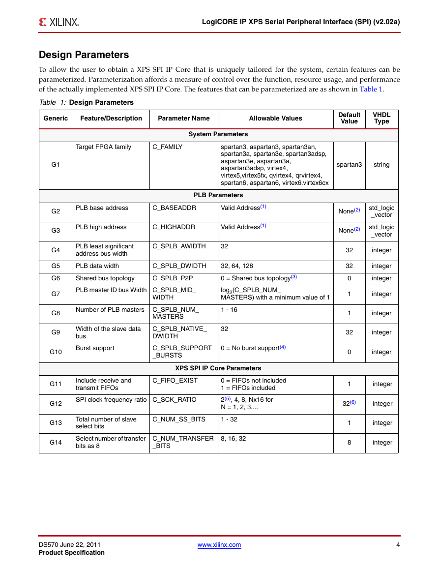
To allow the user to obtain a XPS SPI IP Core that is uniquely tailored for the system, certain features can be
parameterized. Parameterization affords a measure of control over the function, resource usage, and performance
of the actually implemented XPS SPI IP Core. The features that can be parameterized are as shown in Table 1.
Table 1: Design Parameters
Generic
Feature/Description
Parameter Name
Allowable Values
Target FPGA family
C_FAMILY
System Parameters
spartan3, aspartan3, spartan3an,
spartan3a, spartan3e, spartan3adsp,
aspartan3e, aspartan3a,
aspartan3adsp, virtex4,
virtex5,virtex5fx, qvirtex4, qrvirtex4,
spartan6, aspartan6, virtex6.virtex6cx
PLB base address
C_BASEADDR
Valid Address(1)
PLB Parameters
PLB high address
C_HIGHADDR
Valid Address(1)
PLB least significant
address bus width
C_SPLB_AWIDTH
32
PLB data width
C_SPLB_DWIDTH
Shared bus topology
C_SPLB_P2P
32, 64, 128
0 = Shared bus topology(3)
PLB master ID bus Width C_SPLB_MID_
WIDTH
log2(C_SPLB_NUM_
MASTERS) with a minimum value of 1
Number of PLB masters C_SPLB_NUM_
MASTERS
1 - 16
Width of the slave data
bus
C_SPLB_NATIVE_
DWIDTH
32
Burst support
C_SPLB_SUPPORT
_BURSTS
0 = No burst support(4)
XPS SPI IP Core Parameters
Include receive and
transmit FIFOs
C_FIFO_EXIST
SPI clock frequency ratio C_SCK_RATIO
0 = FIFOs not included
1 = FIFOs included
2(5), 4, 8, Nx16 for
N = 1, 2, 3....
Total number of slave
select bits
C_NUM_SS_BITS
1 - 32
Select number of transfer
bits as 8
C_NUM_TRANSFER
_BITS
8, 16, 32
G1
G2
G3
G4
G5
G6
G7
G8
G9
G10
G11
G12
G13
G14
Default
Value
VHDL
Type
spartan3
string
None(2)
None(2)
std_logic
_vector
std_logic
_vector
32
32
0
1
1
integer
integer
integer
integer
integer
32
integer
0
1
integer
integer
32(6)
integer
1
8
integer
integer
DS570 June 22, 2011
Product Specification
www.xilinx.com
4
�
LogiCORE IP XPS Serial Peripheral Interface (SPI) (v2.02a)
Table 1: Design Parameters (Cont’d)
Generic
Feature/Description
Parameter Name
Allowable Values
Default
Value
VHDL
Type
Notes:
1.
The range C_BASEADDR to C_HIGHADDR is the address range for the XPS SPI IP Courthouse range is subject to restrictions
to accommodate the simple address decoding scheme that is employed: The size, C_HIGHADDR - C_BASEADDR + 1, must be
a power of two and must be at least 0x80 to accommodate all XPS SPI IP Core registers. However, a larger power of two may be
chosen to reduce decoding logic. C_BASEADDR must be aligned to a multiple of the range size.
2. No default value will be specified to insure that an actual value appropriate to the system is set. User must set the values.
3. Point to point bus topology is not allowed in this version of XPS SPI IP Core.
4. Burst to-from PLB is not supported in this version of XPS SPI IP Core.
5. C_SCK_RATIO = 2 is not supported when XPS SPI IP Core is configured as slave. So, user must take care in not configuring
C_SCK_RATIO = 2 while using XPS SPI IP Core as slave.
6. Please read the Precautions to be Taken while Assigning the C_SCK_RATIO Parameter section carefully while using this
parameter.
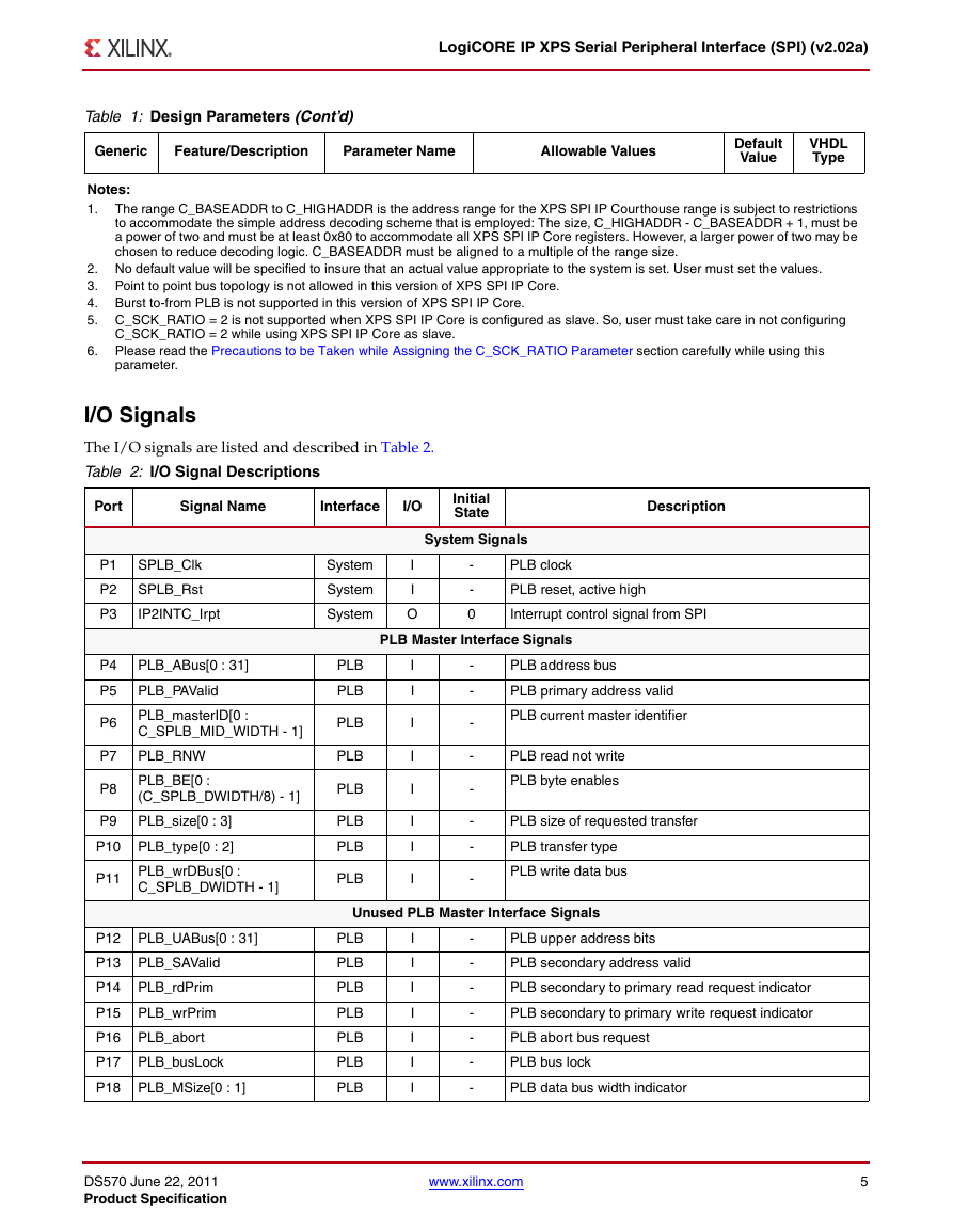
I/O Signals
The I/O signals are listed and described in Table 2.
Table 2: I/O Signal Descriptions
Port
Signal Name
Interface
I/O
Initial
State
System Signals
Description
P1
P2
P3
P4
P5
P6
P7
P8
P9
SPLB_Clk
SPLB_Rst
IP2INTC_Irpt
PLB_ABus[0 : 31]
PLB_PAValid
PLB_masterID[0 :
C_SPLB_MID_WIDTH - 1]
PLB_RNW
PLB_BE[0 :
(C_SPLB_DWIDTH/8) - 1]
PLB_size[0 : 3]
P10 PLB_type[0 : 2]
P11 PLB_wrDBus[0 :
C_SPLB_DWIDTH - 1]
P12 PLB_UABus[0 : 31]
P13 PLB_SAValid
P14 PLB_rdPrim
P15 PLB_wrPrim
P16 PLB_abort
P17 PLB_busLock
P18 PLB_MSize[0 : 1]
System
System
System
I
I
O
-
-
0
PLB clock
PLB reset, active high
Interrupt control signal from SPI
PLB Master Interface Signals
PLB
PLB
PLB
PLB
PLB
PLB
PLB
PLB
I
I
I
I
I
I
I
I
-
-
-
-
-
-
-
-
PLB address bus
PLB primary address valid
PLB current master identifier
PLB read not write
PLB byte enables
PLB size of requested transfer
PLB transfer type
PLB write data bus
Unused PLB Master Interface Signals
PLB
PLB
PLB
PLB
PLB
PLB
PLB
I
I
I
I
I
I
I
-
-
-
-
-
-
-
PLB upper address bits
PLB secondary address valid
PLB secondary to primary read request indicator
PLB secondary to primary write request indicator
PLB abort bus request
PLB bus lock
PLB data bus width indicator
DS570 June 22, 2011
Product Specification
www.xilinx.com
5
�
LogiCORE IP XPS Serial Peripheral Interface (SPI) (v2.02a)
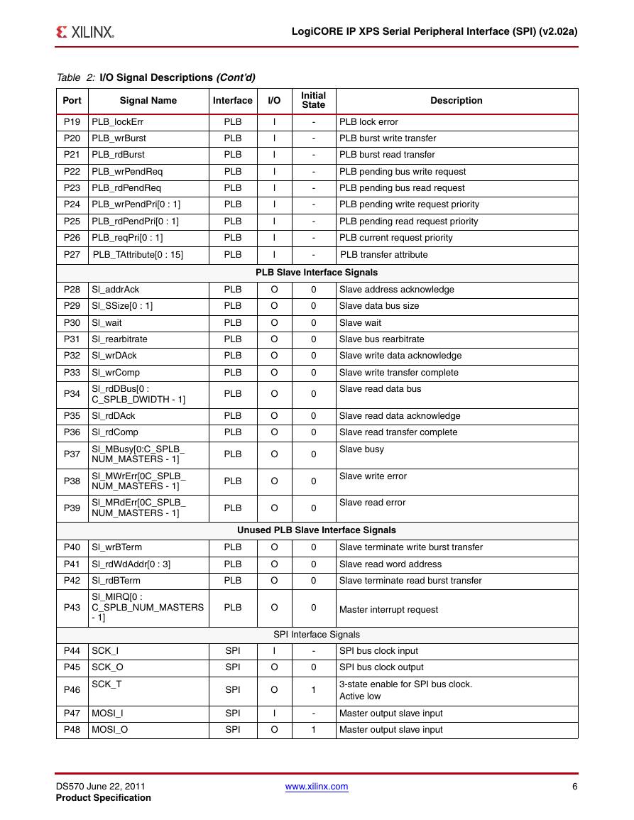
Table 2: I/O Signal Descriptions (Cont’d)
Port
Signal Name
Interface
I/O
Initial
State
Description
P19 PLB_lockErr
P20 PLB_wrBurst
P21 PLB_rdBurst
P22 PLB_wrPendReq
P23 PLB_rdPendReq
P24 PLB_wrPendPri[0 : 1]
P25 PLB_rdPendPri[0 : 1]
P26 PLB_reqPri[0 : 1]
P27
PLB_TAttribute[0 : 15]
P28 Sl_addrAck
P29 Sl_SSize[0 : 1]
P30 Sl_wait
P31 Sl_rearbitrate
P32 Sl_wrDAck
P33 Sl_wrComp
P34 Sl_rdDBus[0 :
C_SPLB_DWIDTH - 1]
P35 Sl_rdDAck
P36 Sl_rdComp
P37 Sl_MBusy[0:C_SPLB_
NUM_MASTERS - 1]
P38 Sl_MWrErr[0C_SPLB_
NUM_MASTERS - 1]
P39 Sl_MRdErr[0C_SPLB_
NUM_MASTERS - 1]
P40 Sl_wrBTerm
P41 Sl_rdWdAddr[0 : 3]
P42 Sl_rdBTerm
P43
Sl_MIRQ[0 :
C_SPLB_NUM_MASTERS
- 1]
P44 SCK_I
P45 SCK_O
SCK_T
P46
P47 MOSI_I
P48 MOSI_O
PLB
PLB
PLB
PLB
PLB
PLB
PLB
PLB
PLB
PLB
PLB
PLB
PLB
PLB
PLB
PLB
PLB
PLB
PLB
PLB
PLB
I
I
I
I
I
I
I
I
I
-
-
-
-
-
-
-
-
-
PLB lock error
PLB burst write transfer
PLB burst read transfer
PLB pending bus write request
PLB pending bus read request
PLB pending write request priority
PLB pending read request priority
PLB current request priority
PLB transfer attribute
PLB Slave Interface Signals
O
O
O
O
O
O
O
O
O
O
O
O
0
0
0
0
0
0
0
0
0
0
0
0
Slave address acknowledge
Slave data bus size
Slave wait
Slave bus rearbitrate
Slave write data acknowledge
Slave write transfer complete
Slave read data bus
Slave read data acknowledge
Slave read transfer complete
Slave busy
Slave write error
Slave read error
Unused PLB Slave Interface Signals
PLB
PLB
PLB
PLB
SPI
SPI
SPI
SPI
SPI
O
O
O
O
0
0
0
0
Slave terminate write burst transfer
Slave read word address
Slave terminate read burst transfer
Master interrupt request
SPI Interface Signals
I
O
O
I
O
-
0
1
-
1
SPI bus clock input
SPI bus clock output
3-state enable for SPI bus clock.
Active low
Master output slave input
Master output slave input
DS570 June 22, 2011
Product Specification
www.xilinx.com
6
�
LogiCORE IP XPS Serial Peripheral Interface (SPI) (v2.02a)
Table 2: I/O Signal Descriptions (Cont’d)
Signal Name
Interface
I/O
Initial
State
Description
Port
P49
MOSI_T
P50 MISO_I
P51 MISO_O
MISO_T
P52
P53
SPISEL(1)
P54 SS_I[0 : C_NUM_SS_BITS
- 1]
P55 SS_O[0 :
C_NUM_SS_BITS - 1]
P56 SS_T
SPI
SPI
SPI
SPI
SPI
SPI
SPI
SPI
O
I
O
O
I
I
O
O
1
-
1
1
1
-
1
1
3-state enable master output slave input.
Active low
Master input slave output
Master input slave output
3-state enable master input slave output.
Active low
Local SPI slave select active low input.
Must be set to 1 in idle state
Input one-hot encoded. This signal is a dummy signal and
wont be used in the design as chip select input
Output one-hot encoded, active low slave select vector of
length n
3-state enable for slave select. Active low
Notes:
1. SPISEL signal is used as a slave select line when XPS SPI is configured as slave.
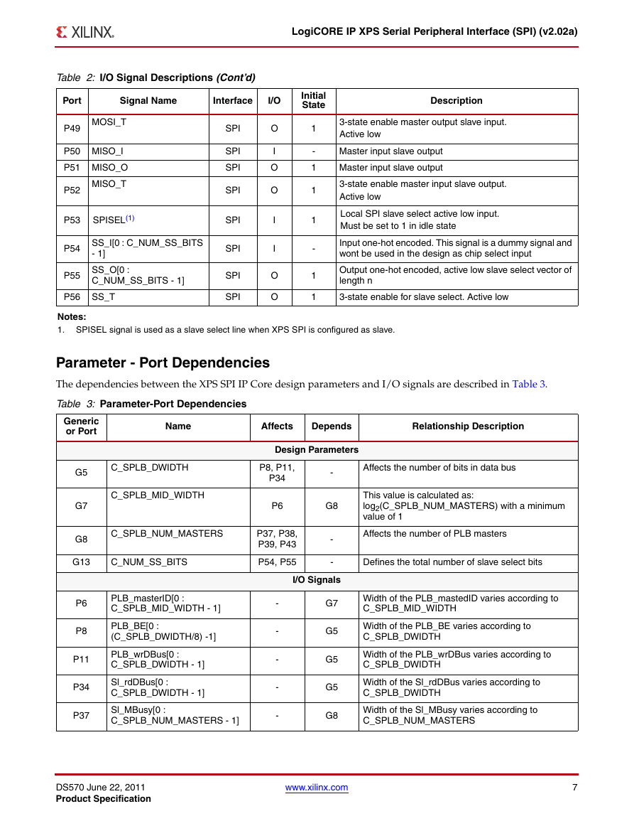
Parameter - Port Dependencies
The dependencies between the XPS SPI IP Core design parameters and I/O signals are described in Table 3.
Table 3: Parameter-Port Dependencies
Name
Affects
Depends
Relationship Description
Generic
or Port
G5
G7
G8
C_SPLB_DWIDTH
C_SPLB_MID_WIDTH
C_SPLB_NUM_MASTERS
G13
C_NUM_SS_BITS
P6
P8
P11
P34
P37
PLB_masterID[0 :
C_SPLB_MID_WIDTH - 1]
PLB_BE[0 :
(C_SPLB_DWIDTH/8) -1]
PLB_wrDBus[0 :
C_SPLB_DWIDTH - 1]
Sl_rdDBus[0 :
C_SPLB_DWIDTH - 1]
Sl_MBusy[0 :
C_SPLB_NUM_MASTERS - 1]
Design Parameters
P8, P11,
P34
P6
P37, P38,
P39, P43
P54, P55
-
G8
-
-
I/O Signals
Affects the number of bits in data bus
This value is calculated as:
log2(C_SPLB_NUM_MASTERS) with a minimum
value of 1
Affects the number of PLB masters
Defines the total number of slave select bits
-
-
-
-
-
G7
G5
G5
G5
G8
Width of the PLB_mastedID varies according to
C_SPLB_MID_WIDTH
Width of the PLB_BE varies according to
C_SPLB_DWIDTH
Width of the PLB_wrDBus varies according to
C_SPLB_DWIDTH
Width of the Sl_rdDBus varies according to
C_SPLB_DWIDTH
Width of the Sl_MBusy varies according to
C_SPLB_NUM_MASTERS
DS570 June 22, 2011
Product Specification
www.xilinx.com
7
�
LogiCORE IP XPS Serial Peripheral Interface (SPI) (v2.02a)
Table 3: Parameter-Port Dependencies (Cont’d)
Generic
or Port
P38
P39
P43
P54
P55
Name
Affects
Depends
Relationship Description
Sl_MWrErr[0 :
C_SPLB_NUM_MASTERS - 1]
Sl_MRdErr[0 :
C_SPLB_NUM_MASTERS - 1]
Sl_MIRQ[0 :
C_SPLB_NUM_MASTERS - 1]
SS_I[0 : C_NUM_SS_BITS - 1]
SS_O[0 : C_NUM_SS_BITS - 1]
-
-
-
-
-
G8
G8
G8
G13
G13
Width of the Sl_MWrErr varies according to
C_SPLB_NUM_MASTERS
Width of the Sl_MRdErr varies according to
C_SPLB_NUM_MASTERS
Width of the Sl_MIRQ varies according to
C_SPLB_NUM_MASTERS
The number of SS_I pins are generated based on
C_NUM_SS_BITS
The number of SS_O pins are generated based on
C_NUM_SS_BITS
Register Descriptions
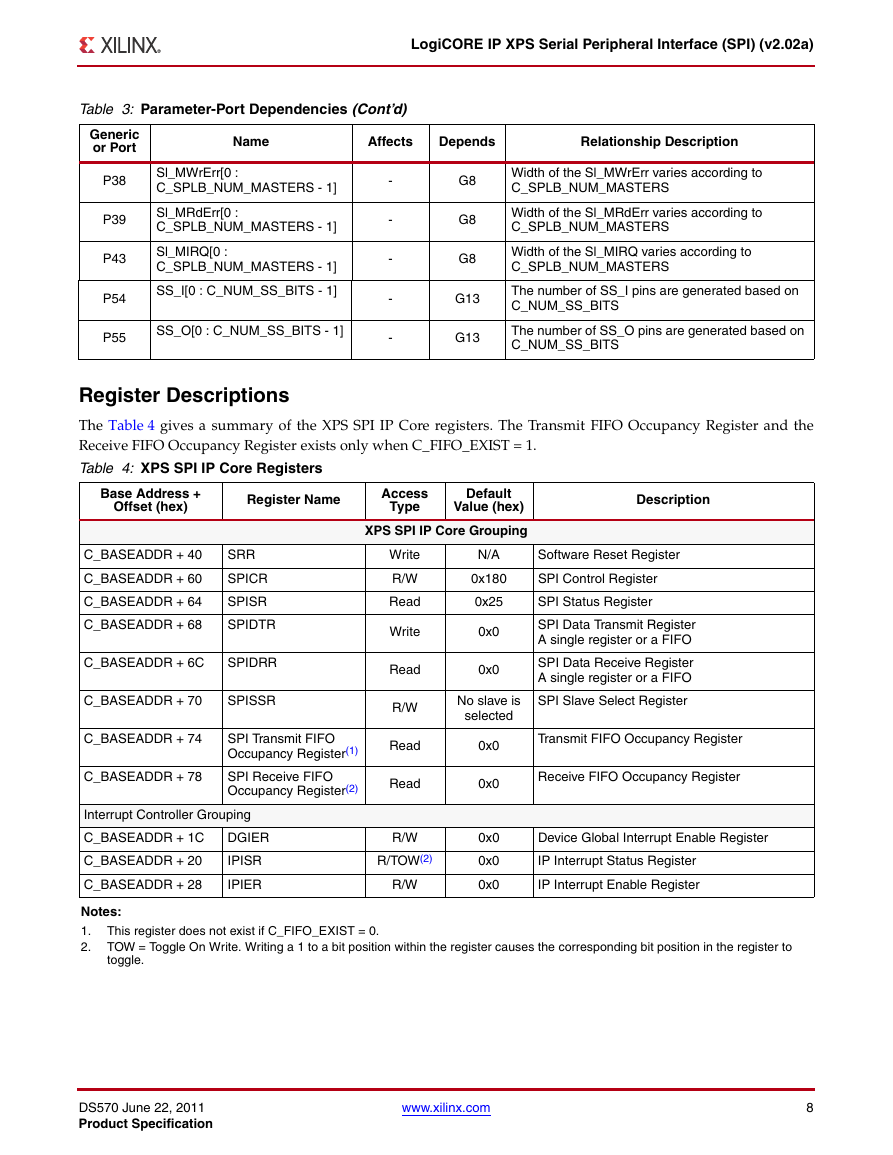
The Table 4 gives a summary of the XPS SPI IP Core registers. The Transmit FIFO Occupancy Register and the
Receive FIFO Occupancy Register exists only when C_FIFO_EXIST = 1.
Table 4: XPS SPI IP Core Registers
Base Address +
Offset (hex)
Register Name
Access
Type
Default
Value (hex)
XPS SPI IP Core Grouping
Description
C_BASEADDR + 40
SRR
C_BASEADDR + 60
C_BASEADDR + 64
SPICR
SPISR
C_BASEADDR + 68
SPIDTR
C_BASEADDR + 6C
SPIDRR
C_BASEADDR + 70
SPISSR
C_BASEADDR + 74
C_BASEADDR + 78
SPI Transmit FIFO
Occupancy Register(1)
SPI Receive FIFO
Occupancy Register(2)
Interrupt Controller Grouping
C_BASEADDR + 1C
DGIER
C_BASEADDR + 20
C_BASEADDR + 28
IPISR
IPIER
Write
R/W
Read
Write
Read
R/W
Read
Read
R/W
R/TOW(2)
R/W
N/A
0x180
0x25
0x0
0x0
No slave is
selected
Software Reset Register
SPI Control Register
SPI Status Register
SPI Data Transmit Register
A single register or a FIFO
SPI Data Receive Register
A single register or a FIFO
SPI Slave Select Register
0x0
0x0
0x0
0x0
0x0
Transmit FIFO Occupancy Register
Receive FIFO Occupancy Register
Device Global Interrupt Enable Register
IP Interrupt Status Register
IP Interrupt Enable Register
Notes:
1.
2.
This register does not exist if C_FIFO_EXIST = 0.
TOW = Toggle On Write. Writing a 1 to a bit position within the register causes the corresponding bit position in the register to
toggle.
DS570 June 22, 2011
Product Specification
www.xilinx.com
8
�




 2023年江西萍乡中考道德与法治真题及答案.doc
 2012年重庆南川中考生物真题及答案.doc
 2013年江西师范大学地理学综合及文艺理论基础考研真题.doc
 2020年四川甘孜小升初语文真题及答案I卷.doc
 2020年注册岩土工程师专业基础考试真题及答案.doc
 2023-2024学年福建省厦门市九年级上学期数学月考试题及答案.doc
 2021-2022学年辽宁省沈阳市大东区九年级上学期语文期末试题及答案.doc
 2022-2023学年北京东城区初三第一学期物理期末试卷及答案.doc
 2018上半年江西教师资格初中地理学科知识与教学能力真题及答案.doc
 2012年河北国家公务员申论考试真题及答案-省级.doc
 2020-2021学年江苏省扬州市江都区邵樊片九年级上学期数学第一次质量检测试题及答案.doc
 2022下半年黑龙江教师资格证中学综合素质真题及答案.doc