Copyright (C) 2020, Texas Instruments Incorporated
http://www.ti.com
MMWAVE SDK User Guide
MMWAVE SDK User Guide
Product Release 3.5
Release Date: Sept 30, 2020
Document Version: 1.0
1
�
Copyright (C) 2020, Texas Instruments Incorporated
http://www.ti.com
MMWAVE SDK User Guide
DOCUMENT LICENSE
This work is licensed under the Creative Commons Attribution-Share Alike 3.0 United States License (CC BY-SA 3.0). To view a copy of this license,
visit
California, 94105, USA.
or send a letter to Creative Commons, 171 Second Street, Suite 300, San Francisco,
http://creativecommons.org/licenses/by-sa/3.0/us/
COPYRIGHT
Copyright (C) 2014 - 2020 Texas Instruments Incorporated - http://www.ti.com
DISCLAIMER
This mmWave SDK User guide is generic and contains details about all the mmWave devices that are supported by TI in general. However, note that
not all mmWave devices may be supported in a given mmWave SDK release. Please refer to the mmWave SDK Release notes to understand the list
of devices/platforms supported in a given mmWave SDK release.
NOTICE:
This software product is used to configure TI’s mmWave devices, including RF emissions parameters for such devices. Note
that many countries or regions impose regulations governing RF emissions. Users are responsible for understanding local RF emission
regulations and operating the product within those regulations.
2
�
Copyright (C) 2020, Texas Instruments Incorporated
http://www.ti.com
MMWAVE SDK User Guide
CONTENTS
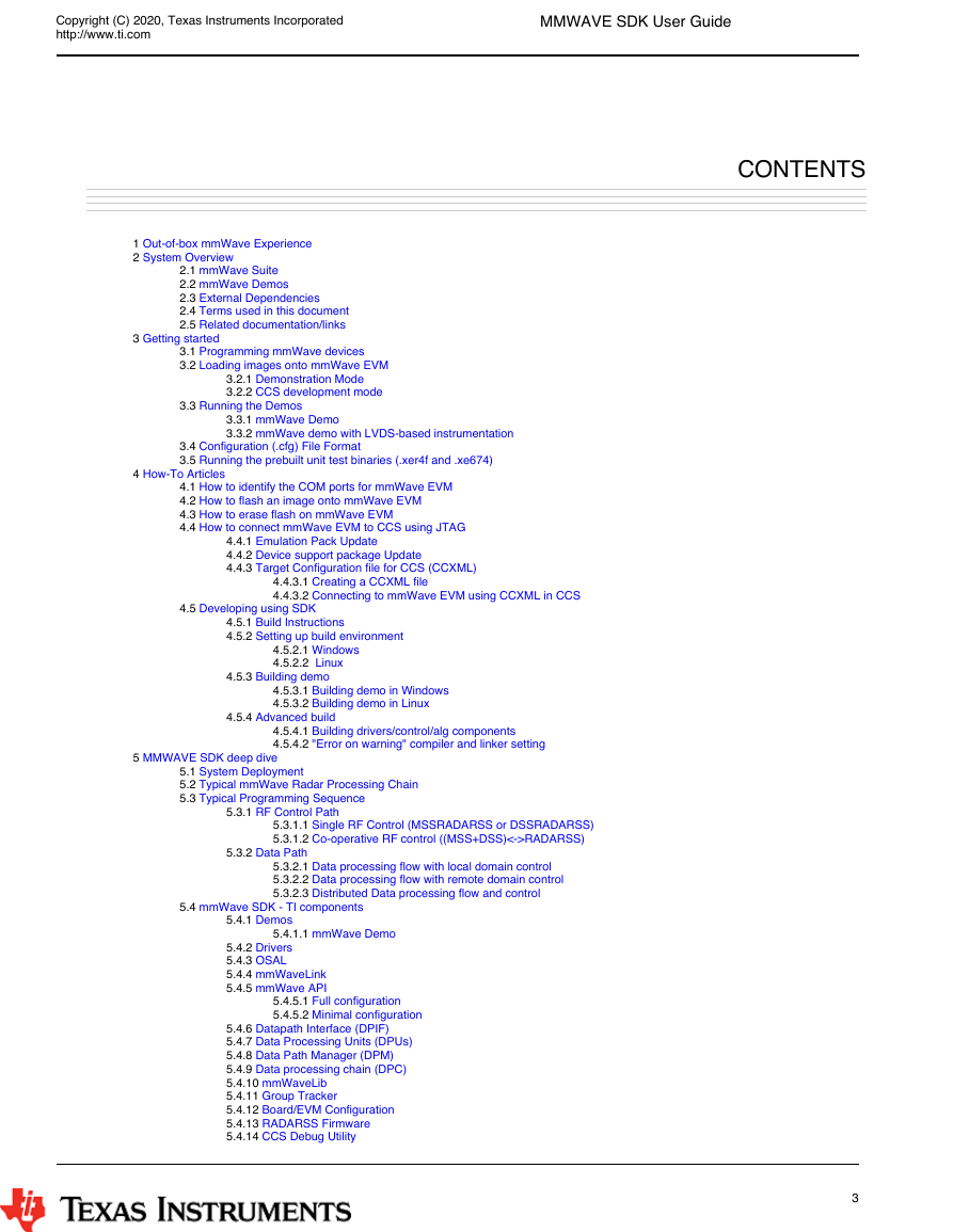
1 Out-of-box mmWave Experience
2 System Overview
2.1 mmWave Suite
2.2 mmWave Demos
2.3 External Dependencies
2.4 Terms used in this document
2.5 Related documentation/links
3 Getting started
3.1 Programming mmWave devices
3.2 Loading images onto mmWave EVM
3.2.1 Demonstration Mode
3.2.2 CCS development mode
3.3 Running the Demos
3.3.1 mmWave Demo
3.3.2 mmWave demo with LVDS-based instrumentation
3.4 Configuration (.cfg) File Format
3.5 Running the prebuilt unit test binaries (.xer4f and .xe674)
4 How-To Articles
4.1 How to identify the COM ports for mmWave EVM
4.2 How to flash an image onto mmWave EVM
4.3 How to erase flash on mmWave EVM
4.4 How to connect mmWave EVM to CCS using JTAG
4.4.1 Emulation Pack Update
4.4.2 Device support package Update
4.4.3 Target Configuration file for CCS (CCXML)
4.4.3.1 Creating a CCXML file
4.4.3.2 Connecting to mmWave EVM using CCXML in CCS
4.5 Developing using SDK
4.5.1 Build Instructions
4.5.2 Setting up build environment
4.5.2.1 Windows
4.5.2.2 Linux
4.5.3 Building demo
4.5.3.1 Building demo in Windows
4.5.3.2 Building demo in Linux
4.5.4 Advanced build
4.5.4.1 Building drivers/control/alg components
4.5.4.2 "Error on warning" compiler and linker setting
5 MMWAVE SDK deep dive
5.1 System Deployment
5.2 Typical mmWave Radar Processing Chain
5.3 Typical Programming Sequence
5.3.1 RF Control Path
5.3.1.1 Single RF Control (MSSRADARSS or DSSRADARSS)
5.3.1.2 Co-operative RF control ((MSS+DSS)<->RADARSS)
5.3.2 Data Path
5.3.2.1 Data processing flow with local domain control
5.3.2.2 Data processing flow with remote domain control
5.3.2.3 Distributed Data processing flow and control
5.4 mmWave SDK - TI components
5.4.1 Demos
5.4.1.1 mmWave Demo
5.4.2 Drivers
5.4.3 OSAL
5.4.4 mmWaveLink
5.4.5 mmWave API
5.4.5.1 Full configuration
5.4.5.2 Minimal configuration
5.4.6 Datapath Interface (DPIF)
5.4.7 Data Processing Units (DPUs)
5.4.8 Data Path Manager (DPM)
5.4.9 Data processing chain (DPC)
5.4.10 mmWaveLib
5.4.11 Group Tracker
5.4.12 Board/EVM Configuration
5.4.13 RADARSS Firmware
5.4.14 CCS Debug Utility
3
�
Copyright (C) 2020, Texas Instruments Incorporated
http://www.ti.com
MMWAVE SDK User Guide
5.4.15 HSI Header Utility
5.4.16 Secondary Bootloader
5.4.17 mmWave SDK - System Initialization
5.4.17.1 ESM
5.4.17.2 SOC
5.4.17.3 Pinmux
5.4.18 Usecases
5.4.18.1 Data Path tests using Test vector method
5.4.18.2 CSI-2 based streaming of ADC data
5.4.18.3 Basic configuration of Front end and capturing ADC data in L3 memory
6 Appendix
6.1 Memory usage
6.2 Register layout
6.3 Enable DebugP logs
6.4 Shared memory usage by SDK demos
6.5 mmWave Device Image Creator
6.6 mmw Demo: cryptic message seen on DebugP_assert
6.7 How to execute Idle instruction in idle task when using SYSBIOS
6.8 Range Bias and Rx Channel Gain/Offset Measurement and Compensation
6.9 Guidelines on optimizing memory usage
6.10 How to add a .const (table) beyond L3 heap in mmWave application where overlay is enabled
6.11 Enabling L3 cache for DSP/C674x on mmWave devices
6.12 DSPlib integration in mmWave C674x based application (Using 2 libraries simultaneously)
6.12.1 Integrating individual functions from each library
6.12.2 Patching the installation
6.13 SDK Demos: miscellaneous information
6.14 Data size restriction for a given session when sending data over LVDS
6.15 CCS Debugging of real time application
6.15.1 Inter-chirp debugging
6.15.2 Inter-frame debugging
6.15.3 Using non-real time chain test code
6.15.4 Using printfs in real time
6.15.5 Viewing hardware registers
6.15.6 Viewing expressions/memory in real time
6.16 Size of Enum
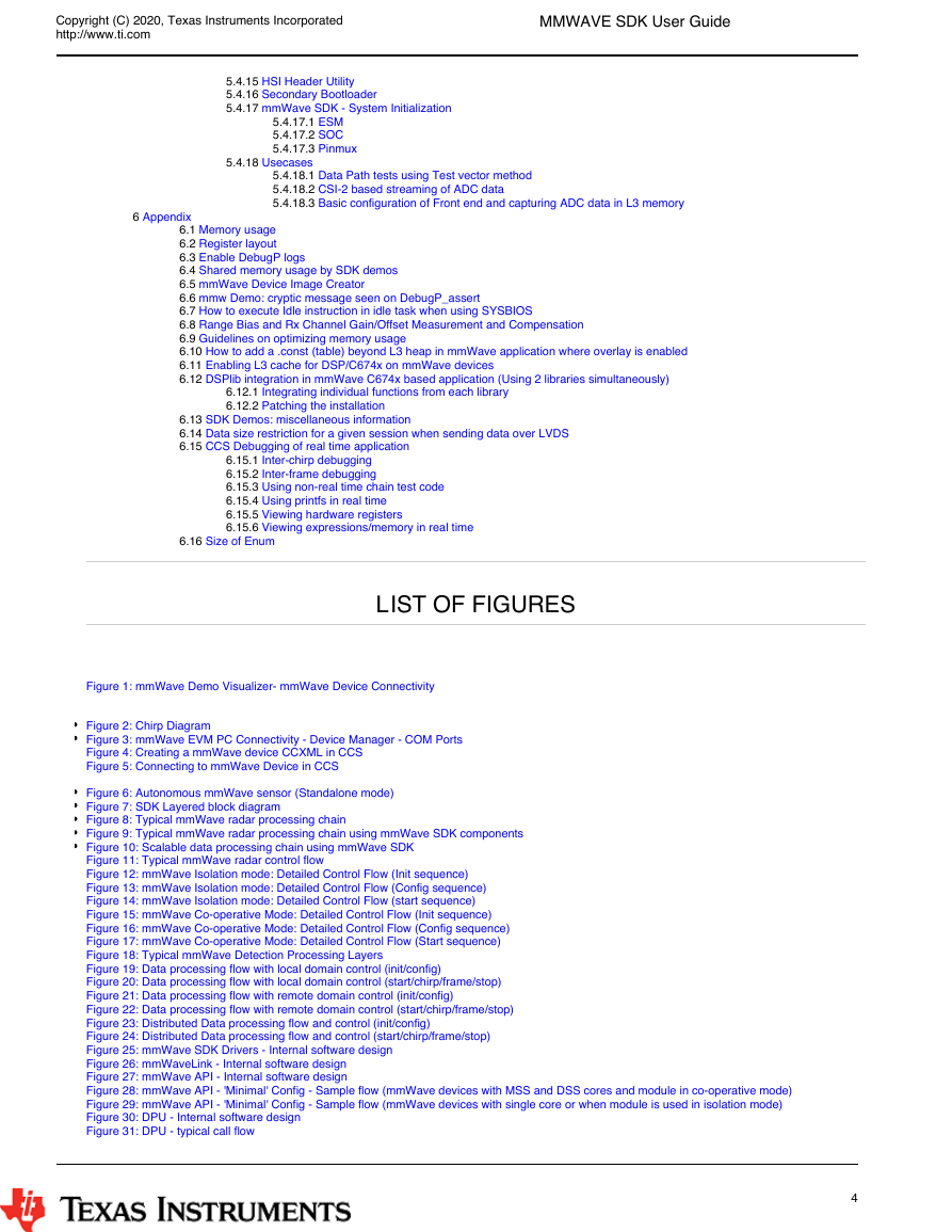
LIST OF FIGURES
Figure 1: mmWave Demo Visualizer- mmWave Device Connectivity
Figure 2: Chirp Diagram
Figure 3: mmWave EVM PC Connectivity - Device Manager - COM Ports
Figure 4: Creating a mmWave device CCXML in CCS
Figure 5: Connecting to mmWave Device in CCS
Figure 6: Autonomous mmWave sensor (Standalone mode)
Figure 7: SDK Layered block diagram
Figure 8: Typical mmWave radar processing chain
Figure 9: Typical mmWave radar processing chain using mmWave SDK components
Figure 10: Scalable data processing chain using mmWave SDK
Figure 11: Typical mmWave radar control flow
Figure 12: mmWave Isolation mode: Detailed Control Flow (Init sequence)
Figure 13: mmWave Isolation mode: Detailed Control Flow (Config sequence)
Figure 14: mmWave Isolation mode: Detailed Control Flow (start sequence)
Figure 15: mmWave Co-operative Mode: Detailed Control Flow (Init sequence)
Figure 16: mmWave Co-operative Mode: Detailed Control Flow (Config sequence)
Figure 17: mmWave Co-operative Mode: Detailed Control Flow (Start sequence)
Figure 18: Typical mmWave Detection Processing Layers
Figure 19: Data processing flow with local domain control (init/config)
Figure 20: Data processing flow with local domain control (start/chirp/frame/stop)
Figure 21: Data processing flow with remote domain control (init/config)
Figure 22: Data processing flow with remote domain control (start/chirp/frame/stop)
Figure 23: Distributed Data processing flow and control (init/config)
Figure 24: Distributed Data processing flow and control (start/chirp/frame/stop)
Figure 25: mmWave SDK Drivers - Internal software design
Figure 26: mmWaveLink - Internal software design
Figure 27: mmWave API - Internal software design
Figure 28: mmWave API - 'Minimal' Config - Sample flow (mmWave devices with MSS and DSS cores and module in co-operative mode)
Figure 29: mmWave API - 'Minimal' Config - Sample flow (mmWave devices with single core or when module is used in isolation mode)
Figure 30: DPU - Internal software design
Figure 31: DPU - typical call flow
4
�
Copyright (C) 2020, Texas Instruments Incorporated
http://www.ti.com
MMWAVE SDK User Guide
Figure 32: Datapath manager (DPM) - internal software design
Figure 33: Sample ROV log with debug prints
LIST OF TABLES
Table 1: mmWave SDK Demos - CLI commands and parameters
Table 2: Supported drivers and their functionality
5
�
Copyright (C) 2020, Texas Instruments Incorporated
http://www.ti.com
MMWAVE SDK User Guide
1. Out-of-box mmWave Experience
To experience the mmWave technology offered by TI, you will need to procure the following
Hardware
mmWave TI EVM
Power supply cable as recommended in TI EVM user guide
PC
1.
2.
3.
Software
1.
2.
Pre-flashed mmWave Demo running on TI EVM (See instructions in this user guide on how to update the flashed demo)
Chrome browser running on PC
Next, to visualize the data flowing out of TI mmWave devices, follow these steps
1.
2.
3.
Connect the EVM to a power outlet via the power cable and to the PC via the included USB cable. EVM should be powered up and
connected to PC now.
On your PC, browse to
[No other software installation is needed at this time]
The Visualizer app should detect and connect to your device via COM ports automatically (except for the very first time where users will need
to confirm the selection via OptionsSerial Port). Select the right Platform and SDK version and start your evaluation!
in Chrome browser and follow the prompts to install one-time software.
https://dev.ti.com/mmWaveDemoVisualizer
a.
Hint : Use HelpAbout to know your Platform and SDK version
For details on how to evaluate, any troubleshooting needs and/or to understand the know-how behind these steps, continue reading this SDK User
Guide...
If the flashed demo on the EVM is an old version and you would like to upgrade to latest demo, continue reading this SDK User Guide...
6
�
Copyright (C) 2020, Texas Instruments Incorporated
http://www.ti.com
MMWAVE SDK User Guide
2. System Overview
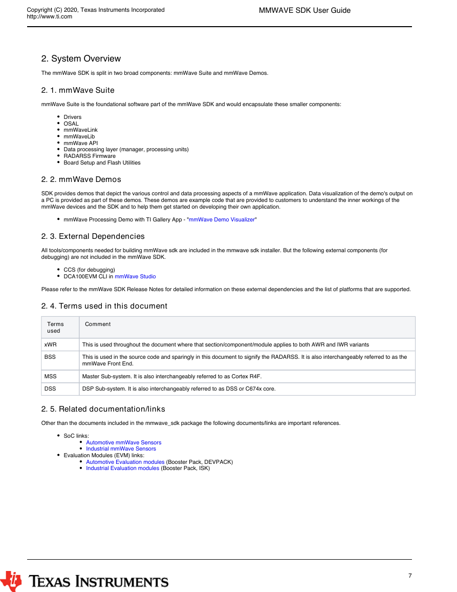
The mmWave SDK is split in two broad components: mmWave Suite and mmWave Demos.
2. 1. mmWave Suite
mmWave Suite is the foundational software part of the mmWave SDK and would encapsulate these smaller components:
Drivers
OSAL
mmWaveLink
mmWaveLib
mmWave API
Data processing layer (manager, processing units)
RADARSS Firmware
Board Setup and Flash Utilities
2. 2. mmWave Demos
SDK provides demos that depict the various control and data processing aspects of a mmWave application. Data visualization of the demo's output on
a PC is provided as part of these demos. These demos are example code that are provided to customers to understand the inner workings of the
mmWave devices and the SDK and to help them get started on developing their own application.
mmWave Processing Demo with TI Gallery App - "
mmWave Demo Visualizer
"
2. 3. External Dependencies
All tools/components needed for building mmWave sdk are included in the mmwave sdk installer. But the following
debugging) are not included in the mmWave SDK.
external components
(for
CCS (for debugging)
DCA100EVM CLI in mmWave Studio
Please refer to the mmWave SDK Release Notes for detailed information on these external dependencies and the list of platforms that are supported.
2. 4. Terms used in this document
Terms
used
Comment
xWR
BSS
MSS
DSS
This is used throughout the document where that section/component/module applies to both AWR and IWR variants
This is used in the source code and sparingly in this document to signify the RADARSS. It is also interchangeably referred to as the
mmWave Front End.
Master Sub-system. It is also interchangeably referred to as Cortex R4F.
DSP Sub-system. It is also interchangeably referred to as DSS or C674x core.
2. 5. Related documentation/links
Other than the documents included in the mmwave_sdk package the following documents/links are important references.
SoC links:
Automotive mmWave Sensors
Industrial mmWave Sensors
Evaluation Modules (EVM) links:
Automotive Evaluation modules (Booster Pack, DEVPACK)
Industrial Evaluation modules (Booster Pack, ISK)
7
�
Copyright (C) 2020, Texas Instruments Incorporated
http://www.ti.com
MMWAVE SDK User Guide
3. Getting started
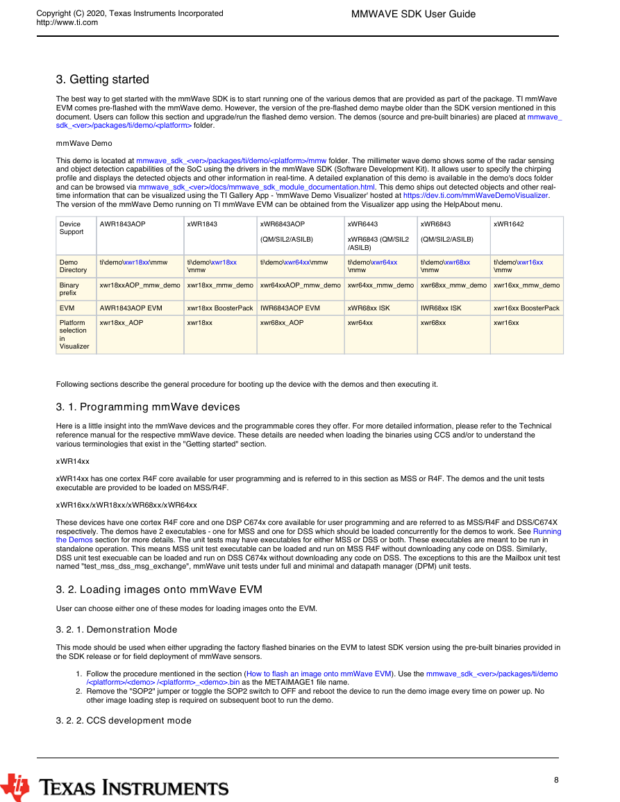
The best way to get started with the mmWave SDK is to start running one of the various demos that are provided as part of the package. TI mmWave
EVM comes pre-flashed with the mmWave demo. However, the version of the pre-flashed demo maybe older than the SDK version mentioned in this
document. Users can follow this section and upgrade/run the flashed demo version. The demos (source and pre-built binaries) are placed at mmwave_
sdk_
/packages/ti/demo/
folder.
mmWave Demo
mmwave_sdk_/packages/ti/demo/
This demo is located at
folder. The millimeter wave demo shows some of the radar sensing
and object detection capabilities of the SoC using the drivers in the mmWave SDK (Software Development Kit). It allows user to specify the chirping
profile and displays the detected objects and other information in real-time. A detailed explanation of this demo is available in the demo's docs folder
and can be browsed via
. This demo ships out detected objects and other real-
time information that can be visualized using the TI Gallery App - 'mmWave Demo Visualizer' hosted at
.
The version of the mmWave Demo running on TI mmWave EVM can be obtained from the Visualizer app using the HelpAbout menu.
mmwave_sdk_/docs/mmwave_sdk_module_documentation.html
https://dev.ti.com/mmWaveDemoVisualizer
/mmw
AWR1843AOP
xWR1843
xWR6843AOP
xWR6443
xWR6843
xWR1642
(QM/SIL2/ASILB)
xWR6843 (QM/SIL2
/ASILB)
(QM/SIL2/ASILB)
ti\demo\
xwr18xx
\mmw
ti\demo\xwr18xx
\mmw
ti\demo\
xwr64xx
\mmw
ti\demo\xwr64xx
\mmw
ti\demo\xwr68xx
\mmw
ti\demo\xwr16xx
\mmw
xwr18xxAOP_mmw_demo xwr18xx_mmw_demo xwr64xxAOP_mmw_demo xwr64xx_mmw_demo xwr68xx_mmw_demo xwr16xx_mmw_demo
AWR1843AOP EVM
xwr18xx BoosterPack
IWR6843AOP EVM
xWR68xx ISK
IWR68xx ISK
xwr16xx BoosterPack
xwr18xx_AOP
xwr18xx
xwr68xx_AOP
xwr64xx
xwr68xx
xwr16xx
Device
Support
Demo
Directory
Binary
prefix
EVM
Platform
selection
in
Visualizer
Following sections describe the general procedure for booting up the device with the demos and then executing it.
3. 1. Programming mmWave devices
Here is a little insight into the mmWave devices and the programmable cores they offer. For more detailed information, please refer to the Technical
reference manual for the respective mmWave device. These details are needed when loading the binaries using CCS and/or to understand the
various terminologies that exist in the "Getting started" section.
xWR14xx
xWR14xx has one cortex R4F core available for user programming and is referred to in this section as MSS or R4F. The demos and the unit tests
executable are provided to be loaded on MSS/R4F.
xWR16xx/xWR18xx/xWR68xx/xWR64xx
These devices have one cortex R4F core and one DSP C674x core available for user programming and are referred to as MSS/R4F and DSS/C674X
respectively. The demos have 2 executables - one for MSS and one for DSS which should be loaded concurrently for the demos to work. See Running
the Demos
section for more details. The unit tests may have executables for either MSS or DSS or both. These executables are meant to be run in
standalone operation. This means MSS unit test executable can be loaded and run on MSS R4F without downloading any code on DSS. Similarly,
DSS unit test execuable can be loaded and run on DSS C674x without downloading any code on DSS. The exceptions to this are the Mailbox unit test
named "test_mss_dss_msg_exchange", mmWave unit tests under full and minimal and datapath manager (DPM) unit tests.
3. 2. Loading images onto mmWave EVM
User can choose either one of these modes for loading images onto the EVM.
3. 2. 1. Demonstration Mode
This mode should be used when either upgrading the factory flashed binaries on the EVM to latest SDK version using the pre-built binaries provided in
the SDK release or for field deployment of mmWave sensors.
1.
2.
Follow the procedure mentioned in the section (
// /_.bin
Remove the "SOP2" jumper or toggle the SOP2 switch to OFF and reboot the device to run the demo image every time on power up. No
other image loading step is required on subsequent boot to run the demo.
How to flash an image onto mmWave EVM . Use the mmwave_sdk_/packages/ti/demo
as the METAIMAGE1 file name.
)
3. 2. 2. CCS development mode
8
�


 2023年江西萍乡中考道德与法治真题及答案.doc
 2012年重庆南川中考生物真题及答案.doc
 2013年江西师范大学地理学综合及文艺理论基础考研真题.doc
 2020年四川甘孜小升初语文真题及答案I卷.doc
 2020年注册岩土工程师专业基础考试真题及答案.doc
 2023-2024学年福建省厦门市九年级上学期数学月考试题及答案.doc
 2021-2022学年辽宁省沈阳市大东区九年级上学期语文期末试题及答案.doc
 2022-2023学年北京东城区初三第一学期物理期末试卷及答案.doc
 2018上半年江西教师资格初中地理学科知识与教学能力真题及答案.doc
 2012年河北国家公务员申论考试真题及答案-省级.doc
 2020-2021学年江苏省扬州市江都区邵樊片九年级上学期数学第一次质量检测试题及答案.doc
 2022下半年黑龙江教师资格证中学综合素质真题及答案.doc