logo资料库

DESfire datasheet.pdf

第1页 / 共79页
第2页 / 共79页
第3页 / 共79页
第4页 / 共79页
第5页 / 共79页
第6页 / 共79页
第7页 / 共79页
第8页 / 共79页
资料共79页,剩余部分请下载后查看
1. General description
2. Features
2.1 RF Interface: ISO 14443 type A
2.2 ISO/IEC 7816 compatibility (only software version 0.6 and higher)
2.3 Non - volatile memory
2.4 NV-memory organisation
2.5 Security
3. Ordering information
4. Block diagram
5. Pinning information
5.1 Pinning
6. Functional description
6.1 Contactless energy and data transfer
6.2 Delivery types
6.3 Anticollision
6.4 UID / serial number
6.5 Memory organisation
6.6 Security concept
6.7 (3)DES-encryption
6.8 MACing
7. MF3 IC D40 - Coding of security-, application- and file- related features
7.1 Coding of file types
7.2 Coding of communication settings - encryption modes
7.3 Coding of access rights
7.4 Coding of status- and error codes
7.5 DESFire command set overview - ISO 14443-3:
7.6 DESFire command set overview - ISO 14443-4:
7.7 MF3 IC D40 command set overview - security related commands:
7.8 MF3 IC D40 command set overview - PICC level commands:
7.9 MF3 IC D40 command set overview - application level commands:
7.10 MF3 IC D80 command set overview - data manipulation commands
7.11 ISO 7816-4 APDU message structure
7.12 Selection of native DESFire APDU framing versus ISO 7816-4 framing and commands
7.13 Wrapping of native DESFire APDUs
7.14 Pre-Selection after entering 14443-4 (only in 7816-4 framing mode)
8. DESFire command set
8.1 Command set ISO 14443-3:
8.1.1 Request type A (REQA)
8.1.2 Wake-Up (WUPA)
8.1.3 ANTICOLLISION and SELECT of cascade level 1
8.1.4 ANTICOLLISION and SELECT of cascade level 2
8.2 Command set ISO 14443-4:
8.2.1 Request for answer to Select (RATS)
8.2.2 Protocol and parameter selection request (PPS)
8.2.3 Frame waiting extensions (WTX)
8.3 MF3 IC D40 command set - security related commands:
8.3.1 Authenticate
8.3.2 ChangeKeySettings
8.3.2.1 PICC master key settings:
8.3.2.2 Application master key settings:
8.3.3 GetKeySettings
8.3.4 ChangeKey
8.3.5 GetKeyVersion
8.4 MF3 IC D40 command set - PICC level commands:
8.4.1 CreateApplication
8.4.2 DeleteApplication
8.4.3 GetApplicationIDs
8.4.4 SelectApplication
8.4.5 FormatPICC
8.4.6 GetVersion
8.5 MF3 IC D40 command set - application level commands:
8.5.1 GetFileIDs
8.5.2 GetFileSettings
8.5.3 ChangeFileSettings
8.5.4 CreateStdDataFile
8.5.5 CreateBackupDataFile
8.5.6 CreateValueFile
8.5.7 CreateLinearRecordFile
8.5.8 CreateCyclicRecordFile
8.5.9 DeleteFile
8.6 MF3 IC D40 command set - data manipulation commands
8.6.1 ReadData
8.6.2 WriteData
8.6.3 GetValue
8.6.4 Credit
8.6.5 Debit
8.6.6 LimitedCredit
8.6.7 WriteRecord
8.6.8 ReadRecords
8.6.9 ClearRecordFile
8.6.10 CommitTransaction
8.6.11 AbortTransaction
8.7 Command Set ISO 7816-4 - basic interindustry commands:
8.7.1 ISO SELECT APPLICATION command
8.7.2 ISO SELECT DIRECTORY command
8.7.3 ISO SELECT FILE command
8.7.4 ISO READ BINARY command
8.7.5 ISO UPDATE BINARY command
9. Limiting values
10. Recommended operating conditions
11. Characteristics
12. Support information
13. Package outline
14. Revision history
15. Legal information
15.1 Data sheet status
15.2 Definitions
15.3 Disclaimers
15.4 Trademarks
16. Contact information
17. Tables
18. Figures
19. Contents
MF3 IC D40 Contactless Multi-Application IC with DES and 3DES Security Mifare DESfire Functional specification Rev. 1.0 — 7 March 2007 075040 Product data sheet CONFIDENTIAL 1. General description NXP has developed the MIFARE DESFire (MF3 IC D40) to be used with Proximity Coupling Devices (PCDs) according to ISO14443 Type A. The communication protocol complies to part ISO 14443-4. The MF3 IC D40 is primarily designed for secure contactless transport applications and related loyalty programs. In addition to ISO 14443 DESFire also support the use of ISO 7816-3 compliant APDU message structure. 2. Features 2.1 RF Interface: ISO 14443 type A Contactless transmission of data and powered by the RF-field (no battery needed) Operating distance: Up to 100 mm (depending on antenna geometry) Operating frequency: 13.56 MHz Fast data transfer: 106 kbit/s, 212 kbit/s, 424 kbit/s High data integrity: 16 Bit CRC, parity, bit coding, bit counting True deterministic anticollision 7 byte unique identifier (cascade level two according to ISO 14443-3) Uses ISO 14443-4 protocol 2.2 ISO/IEC 7816 compatibility (only software version 0.6 and higher) Supports 7816-3 APDU message Structure Supports 7816-4 INS code ‘A4’ SELECT APPLICATION Supports 7816-4 INS code ‘A4’ SELECT DIRECTORY Supports 7816-4 INS code ‘A4’ SELECT FILE Supports 7816-4 INS code ‘B0’ READ BINARY Supports 7816-4 INS code ‘D6’ UPDATE BINARY 2.3 Non - volatile memory 4 kbyte NV-Memory NV-Memory write time 2 ms (1 ms erase, 1 ms program) Data retention of 10 years
NXP Semiconductors MF3 IC D40 Contactless Mifare DESfire Functional specification Write endurance 100 000 cycles 2.4 NV-memory organisation Flexible file system Up to 28 applications simultaneously on one PICC Up to 16 files in each application 2.5 Security Unique 7 Byte serial number for each device Mutual three pass authentication Hardware DES/3DES Data encryption on RF-channel with replay attack protection using 56/112 bit Keys featuring key versioning Data Authenticity by 4 Byte MAC Authentication on Application level Hardware exception sensors Self-securing file system 3. Ordering information MF3 IC D40 can be delivered packaged or on wafer, please see delivery type describtion for more information. 075040 Product data sheet Rev. 1.0 — 7 March 2007 © NXP B.V. 2007. All rights reserved. 2 of 79
NXP Semiconductors 4. Block diagram LA LB CARD CARD COIL COIL MF3 IC D40 Contactless Mifare DESfire Functional specification MF3 IC D40 UART UART ISO 14443A TRIPLE- DES TRIPLE- DES CO- PROCESSOR CO- PROCESSOR TRUE RANDOM NUMBER GENERATOR CPU / Logic Unit CRC ROM RAM RAM EEPROM RF INTERFACE SECURITY SENSORS POWER ON RESET VOLTAGE REGULATOR CLOCK INPUT FILTER RESET GENERATOR Fig 1. Block diagram 5. Pinning information 5.1 Pinning See Delivery Type Addendum of Device 075040 Product data sheet Rev. 1.0 — 7 March 2007 © NXP B.V. 2007. All rights reserved. 3 of 79
NXP Semiconductors 6. Functional description MF3 IC D40 Contactless Mifare DESfire Functional specification 6.1 Contactless energy and data transfer In the MIFARE system, the MF3 IC D40 is connected to a coil consisting of a few turns embedded in a standard ISO smart card. No battery is needed. When the card is positioned in the proximity of the PCD antenna, the high speed RF communication interface allows to transmit data with up to 424 kbit/s. contacts La , Lb Energy Data ISO 14443A PCD 4 turns wire coil MF3 IC D40 chip embedded in MOA4 module Fig 2. Contactless energy and data transfer 6.2 Delivery types MF3 IC D40 can be delivered packaged or on wafer, please see delivery type describtion for more information.. 6.3 Anticollision An intelligent anticollision mechanism allows to handle more than one PICC in the field simultaneously. The anticollision algorithm selects each PICC individually and ensures that the execution of a transaction with a selected PICC is performed correctly without data corruption resulting from other PICCs in the field. 6.4 UID / serial number The unique 7 byte serial number (UID) is programmed into a locked part of the NV-memory which is reserved for the manufacturer. Due to security and system requirements these bytes are write-protected after having been programmed by the IC manufacturer at production time. 075040 Product data sheet Rev. 1.0 — 7 March 2007 © NXP B.V. 2007. All rights reserved. 4 of 79
NXP Semiconductors MF3 IC D40 Contactless Mifare DESfire Functional specification MSB 0 0 0 0 0 1 0 LSB 0 Manufacturer ID for NXP (0x04) Byte SN0 SN1 SN2 SN3 SN4 SN5 SN6 7 Byte unique Serial Number Fig 3. UID / serial number According to ISO14443-3 the first anticollision loop, see Section 8.1.3, will return the cascade tag 0x88 and the first 3 bytes of the UID, SN0 to SN2 and BCC. The second anticollision loop, see Section 8.1.4, will return bytes SN3 to SN6 and BCC.SN0 holds the Manufacturer ID for NXP (04h) according to ISO14443-3 and ISO 7816-6 AMD 1. 6.5 Memory organisation The 4 kbyte NV-memory is organised using a flexible file system. This file system allows a maximum of 28 different applications on one single PICC. Each application provides up to 16 files. Every application is represented by it's 3 bytes Application IDentifier, AID. Five different file types are supported, see Section 7.1. A guideline to assign DESFire AIDs can be found in the application note “Mifare Application Directory, MAD”. Each file can be created either at PICC initialisation (card production / card printing), at PICC personalisation (vending machine) or in the field. If a file or application becomes obsolete in operation, it can be permanently invalidated. Commands which have impact on the file structure itself (e.g. creation or deletion of applications, change of keys…) activate an automatic rollback mechanism, which protects the file structure from getting corrupted. If this rollback is necessary, it is done without user interaction before carrying out further commands. To ensure data integrity on application level, a transaction oriented backup is implemented for all file types with backup. It is possible to mix file types with and without backup within one application, whereby backup is possible only for files 0 .. 7, files 8 .. 15 do not feature backup mechanisms. 075040 Product data sheet Rev. 1.0 — 7 March 2007 © NXP B.V. 2007. All rights reserved. 5 of 79
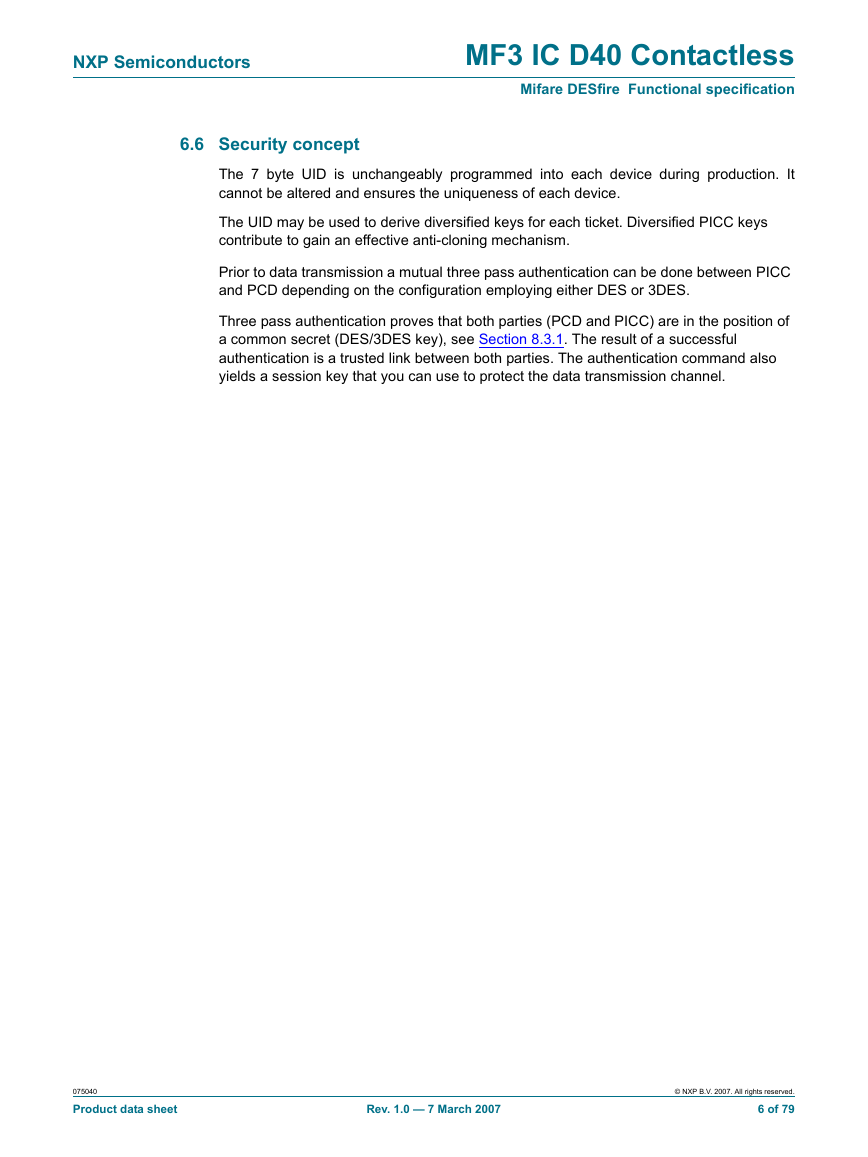
NXP Semiconductors MF3 IC D40 Contactless Mifare DESfire Functional specification 6.6 Security concept The 7 byte UID is unchangeably programmed into each device during production. It cannot be altered and ensures the uniqueness of each device. The UID may be used to derive diversified keys for each ticket. Diversified PICC keys contribute to gain an effective anti-cloning mechanism. Prior to data transmission a mutual three pass authentication can be done between PICC and PCD depending on the configuration employing either DES or 3DES. Three pass authentication proves that both parties (PCD and PICC) are in the position of a common secret (DES/3DES key), see Section 8.3.1. The result of a successful authentication is a trusted link between both parties. The authentication command also yields a session key that you can use to protect the data transmission channel. 075040 Product data sheet Rev. 1.0 — 7 March 2007 © NXP B.V. 2007. All rights reserved. 6 of 79
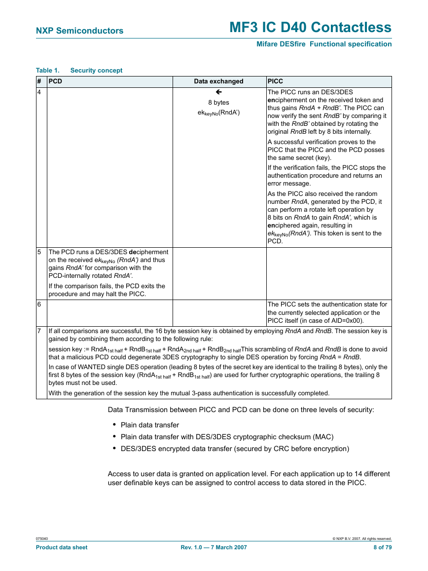
NXP Semiconductors MF3 IC D40 Contactless Mifare DESfire Functional specification Below it is described in detail how the mutual 3-pass authentication procedure is done and how the session key is generated: Data exchanged PICC Authenticate (KeyNo) Security concept Table 1. # PCD 1 The reader device is always the entity which starts an authentication procedure. This is done by sending the command Authenticate. As parameter the key number is passed to the PICC in order to select a certain key stored in its NV-memory (up to 14 different keys per application). If the key number does not reflect a valid key in the PICC memory, an error code is sent by the PICC in response. Depending on the previously selected AID on the PICC, the subsequent authentication procedure is done for this specific AID. If the previously selected AID is 0x00, then the authentication is done using the PICC Master Key. In this case, the parameter key number has to be set to 0x00, too. (The possibilities and usage of the PICC Master Key is described later on.) After power up of the PICC the AID 0x00 is implicitly selected, which means that an Authenticate command after power-up always references the PICC Master Key. After a specific key is selected, the PICC generates an 8 byte random number RndB. This random number is DES/3DES enciphered with the selected key, denoted by ekkeyNo(RndB), and is then transmitted to the PCD. 8 bytes ekkeyNo(RndB) 16 bytes dkkeyNo(RndA+ RndB’) 2 3 The PCD runs a DES/3DES deciphering operation on the received ekkeyNo(RndB) and thus retrieves RndB. (The used key for the deciphering obviously has to be the same as for the previous enciphering by the PICC.) In the next step RndB is rotated left by 8 bits (first byte is moved to the end of RndB), yielding RndB’. Now the PCD itself generates an 8 byte random number RndA. This RndA is concatenated with RndB’ and deciphered using DES/3DES (The decryption of the two blocks is chained using the Cipher Block Chaining (CBC) send mode). This token dkkeyNo(RndA + RndB’) is sent to the PICC. 075040 Product data sheet Rev. 1.0 — 7 March 2007 © NXP B.V. 2007. All rights reserved. 7 of 79
NXP Semiconductors Security concept Table 1. # PCD 4 MF3 IC D40 Contactless Mifare DESfire Functional specification Data exchanged 8 bytes ekkeyNo(RndA’) PICC The PICC runs an DES/3DES encipherment on the received token and thus gains RndA + RndB’. The PICC can now verify the sent RndB’ by comparing it with the RndB’ obtained by rotating the original RndB left by 8 bits internally. A successful verification proves to the PICC that the PICC and the PCD posses the same secret (key). If the verification fails, the PICC stops the authentication procedure and returns an error message. As the PICC also received the random number RndA, generated by the PCD, it can perform a rotate left operation by 8 bits on RndA to gain RndA’, which is enciphered again, resulting in ekkeyNo(RndA’). This token is sent to the PCD. 5 The PCD runs a DES/3DES decipherment on the received ekkeyNo (RndA’) and thus gains RndA’ for comparison with the PCD-internally rotated RndA’. If the comparison fails, the PCD exits the procedure and may halt the PICC. 6 7 The PICC sets the authentication state for the currently selected application or the PICC itself (in case of AID=0x00). If all comparisons are successful, the 16 byte session key is obtained by employing RndA and RndB. The session key is gained by combining them according to the following rule: session key := RndA1st half + RndB1st half + RndA2nd half + RndB2nd halfThis scrambling of RndA and RndB is done to avoid that a malicious PCD could degenerate 3DES cryptography to single DES operation by forcing RndA = RndB. In case of WANTED single DES operation (leading 8 bytes of the secret key are identical to the trailing 8 bytes), only the first 8 bytes of the session key (RndA1st half + RndB1st half) are used for further cryptographic operations, the trailing 8 bytes must not be used. With the generation of the session key the mutual 3-pass authentication is successfully completed. Data Transmission between PICC and PCD can be done on three levels of security: • Plain data transfer • Plain data transfer with DES/3DES cryptographic checksum (MAC) • DES/3DES encrypted data transfer (secured by CRC before encryption) Access to user data is granted on application level. For each application up to 14 different user definable keys can be assigned to control access to data stored in the PICC. 075040 Product data sheet Rev. 1.0 — 7 March 2007 © NXP B.V. 2007. All rights reserved. 8 of 79
分享到:
收藏