logo资料库

JESD204c标准 2017.10.pdf

第1页 / 共294页
第2页 / 共294页
第3页 / 共294页
第4页 / 共294页
第5页 / 共294页
第6页 / 共294页
第7页 / 共294页
第8页 / 共294页
资料共294页,剩余部分请下载后查看
JESD204C
Foreword
1 Scope
2 Normative references
3 Terminology
3.1 Terms and definitions
3.2 Symbols and abbreviated terms
4 Introduction and common requirements
4.1 Application overview
4.1.1 Background
4.1.2 Physical layer overview
4.1.3 Transport and link layer overview
4.1.3.1 Data encoding and organization
4.1.3.2 Clocking
4.1.3.3 Sync header stream
4.1.3.4 Deterministic latency
4.1.4 Data link properties
4.1.4.1 Variants and modes
4.1.5 Configuration examples
4.1.5.1 General
4.1.5.2 Single-device ADC application
4.1.5.3 Single-device DAC application
4.2 Deterministic latency
4.2.1 Introduction and general requirements
4.2.2 No support for deterministic latency (device subclass 0 and device subclass 1 using MULTIREF)
4.2.3 Deterministic latency using SYSREF (device subclass 1)
4.2.4 Deterministic latency using SYNC~ detection (device subclass 2)
4.3 Physical timing
4.3.1 Device clock
4.3.2 Link layer clock
4.3.3 Transport layer clock
4.3.4 Local multiframe and extended multiblock clocks (LMFC and LEMC)
4.3.5 SYSREF signal (device Subclass 1)
4.3.6 MULTIREF signal (device subclass 1)
4.3.7 SYNC~ generation and detection clocks (8B/10B link layer)
4.3.8 Skew and latency variation budget
4.4 Control interfaces
4.5 Device classification
4.5.1 Classes
4.5.2 Device subclassification
4.5.3 Features to be declared
5 Physical layer specification
5.1 Category B physical layer specification
5.1.1 Electrical specification overview
5.1.2 Compliance types
5.1.3 Transmission medium
5.1.3.1 Transmission medium insertion loss
5.1.4 Class B-3 ( LV-OIF-SxI5)
5.1.4.1 Compliance
5.1.4.2 Transmitter
5.1.4.3 Receiver
5.1.5 Class B-6 (LV-OIF-6G-SR)
5.1.5.1 Compliance
5.1.5.2 Transmitter
5.1.5.3 Receiver
5.1.6 Class B-12 (LV-OIF-11G-SR)
5.1.6.1 Applicability above 11.1 Gbps
5.1.6.2 Compliance
5.1.6.3 Transmitter
5.1.6.4 Receiver
5.2 Category C physical layer specification
5.2.1 Overview
5.2.2 Common transmitter electrical specifications
5.2.3 Common receiver electrical specifications
5.2.4 Common JESD204C channel operation margin (JCOM) parameters
5.2.5 Class C-S
5.2.6 Class C-M
5.2.7 Class C-R
5.2.8 Reference channels
5.2.9 Compliance
5.2.9.1 Transmitter
5.2.9.1.1 Device compliance
5.2.9.1.2 Model compliance
5.2.9.2 Receiver
5.2.9.2.1 Device compliance
5.2.9.2.2 Model compliance
5.2.9.3 Channel
5.2.9.4 Isolation
5.2.10 Transmitter definitions
5.2.10.1 Transmitter test fixture
5.2.10.2 Signaling rate and range
5.2.10.3 Signaling levels
5.2.10.4 Transmitter transition (rise/fall) time
5.2.10.5 Transmitter output return loss
5.2.10.6 Transmitter output waveform
5.2.10.7 Transmitter output noise and distortion
5.2.10.8 Waveform acquisition
5.2.10.9 Test pattern
5.2.10.10 Linear fit to the waveform measured at TP0a
5.2.10.11 Removal of the transfer function between the transmit function and TP0a
5.2.10.12 Transmitter output jitter
5.2.10.12.1 Even-odd jitter (DCD)
5.2.10.12.2 Effective bounded uncorrelated jitter (EBUJ) and effective random jitter (ERJ)
5.2.11 Receiver definitions
5.2.11.1 Receiver test fixture
5.2.11.2 Signaling rate and range
5.2.11.3 Signaling levels
5.2.11.4 Receiver input return loss
5.2.11.5 Receiver sensitivity
5.2.11.6 Receiver jitter tolerance
5.2.12 JESD204C channel operation margin (JCOM)
5.2.12.1 Link model
5.2.12.2 Implementation
5.2.12.3 Device class
5.2.12.4 Measurement of the channel
5.2.12.5 Coupling
5.2.12.6 Transmitter and receiver device package models
5.2.12.6.1 Cascade connection of two-port networks
5.2.12.6.2 Two-port network for a differential shunt capacitance
5.2.12.6.3 Two-port network for a differential serial inductor
5.2.12.6.4 Two-port network for a differential series resistance-inductance combination
5.2.12.6.5 Reference device package model
5.2.12.6.6 Isolation
5.2.12.7 Path terminations
5.2.12.8 Filters
5.2.12.8.1 Receive noise filter
5.2.12.8.2 Transmitter equalizer
5.2.12.8.3 Receiver equalizer
5.2.12.8.4 Transmitter transition time adjustment filter
5.2.12.9 Pulse response
5.2.12.10 Determination of variable equalizer parameters
5.2.12.11 Interference and noise amplitude
5.2.12.11.1 Interference amplitude distribution
5.2.12.11.2 Noise amplitude distribution
5.2.12.11.3 Combination of interference and noise distribution
6 Transport layer
6.1 Overview
6.2 User data format for an independent lane
6.2.1 General
6.2.2 User data mapping without oversampling
6.2.3 User data mapping with oversampling
6.3 User data format for multiple lanes
6.4 Tail bits
6.5 Idle mode
6.5.1 General
6.5.2 Dummy Samples
6.6 Test modes
6.6.1 General
6.6.2 Short transport layer test pattern
6.6.3 Long transport layer test pattern
7 64B/66B and 64B/80B link layer
7.1 Overview
7.1.1 64B/66B and 64B/80B encoding
7.1.2 Block structure
7.1.3 Multiblock structure
7.1.4 Extended multiblock structure
7.1.5 Data channel
7.1.6 Sync header stream
7.2 Physical coding sublayer
7.2.1 Overview
7.2.2 Transmit process
7.2.3 Receive process
7.2.4 Scrambling and descrambling
7.2.4.1 Overview
7.2.4.2 Scrambler
7.2.4.3 Descrambler
7.2.5 Fill bits for 64B/80B encoding
7.2.6 Gearbox
7.3 Sync header stream
7.3.1 Overview
7.3.2 Sync header encoding and decoding
7.3.3 Pilot signal
7.3.4 CRC-12 signal
7.3.5 CRC-3 signal
7.3.6 FEC signal
7.3.7 Command channel
7.3.7.1 Overview
7.3.7.2 Stand-alone command channel
7.3.7.3 Command word encoding
7.3.7.4 Header and payload sequence
7.3.7.5 Operating modes
7.3.7.6 Function codes
7.4 CRC encoding
7.4.1 General
7.4.2 CRC-12 encoding
7.4.3 CRC-3 encoding
7.5 FEC encoding
7.5.1 General
7.5.2 FEC encoding
7.5.3 FEC decoding
7.5.3.1 FEC code reconstruction
7.5.3.2 FEC code decoding
7.6 Receiver Operation
7.6.1 Sync header alignment
7.6.2 Extended multiblock alignment
7.6.3 Error handling
7.6.3.1 Error kinds
7.6.3.2 Action taken on error
7.6.3.3 Error reporting via control interface
8 8B/10B link layer
8.1 8B/10B encoding
8.2 Transmission order
8.3 Scrambling
8.3.1 Introduction
8.3.2 Scrambler polynomial
8.3.3 Scrambler bit order
8.3.4 Scrambler type
8.3.5 Early synchronization option
8.3.6 Initial state
8.3.7 Scrambling disable
8.4 Link operation
8.4.1 Code group synchronization
8.4.2 Combination of synchronization requests
8.4.3 Initial frame synchronization
8.4.4 Frame alignment monitoring and correction
8.4.4.1 Alignment characters
8.4.4.2 Character replacement without scrambling
8.4.4.3 Character replacement with scrambling
8.4.4.4 Frame alignment correction in the RX
8.4.5 Initial lane alignment
8.4.5.1 General principles
8.4.5.2 Multiframes
8.4.5.3 Initial lane alignment sequence
8.4.6 Lane alignment monitoring and correction
8.4.7 Link re-initialization
8.4.8 Test modes
8.4.8.1 General
8.4.8.2 Test sequences
8.5 Deterministic latency using SYNC~ detection (device subclass 2)
8.5.1 Introduction
8.5.2 Accuracy limitations
8.5.3 Principles of SYNC~ sampling
8.5.3.1 General
8.5.3.2 SYNC~ generation at the RX device
8.5.3.3 Adjustment resolution and adjustment clock
8.5.3.4 Detection resolution at the TX device
8.5.3.5 SYNC~ de-assertion detection and the detection interval
8.5.4 Master and slave configurations
8.5.4.1 Introduction
8.5.4.2 ADC master and slave configurations
8.5.4.3 DAC master and slave configurations
8.5.5 Summary of requirements for subclass 2 deterministic latency
8.6 Receiver operation
8.6.1 Code group synchronization
8.6.2 Initial frame synchronization
8.6.3 Initial lane alignment
8.6.4 Monitoring and correction of frame and lane alignment
8.6.5 Error handling
8.6.5.1 Error kinds
8.6.5.2 Data output on error
8.6.5.3 Errors requiring re-initialization
8.6.5.4 Error reporting via the SYNC interface
8.6.5.5 Error reporting via a control interface
8.7 Transmitter operation
8.7.1 Synchronization
8.7.2 Handling of error reports and synchronization requests
8.7.2.1 Hard-wired SYNC interface
8.7.2.2 Soft SYNC interface
8.7.3 SYNC~ detection in device subclass 2
8.8 SYNC interface
8.8.1 Introduction
8.8.2 Hard-wired SYNC interface
8.8.3 Soft SYNC interface
8.9 Link configuration parameters and their encoding
Annex A (informative) Differences between revisions
Annex B (informative) Example of device clock and SYSREF generation
Annex C (informative) Background of the values in the skew budget
C.1 Transmission skew
C.2 Timing reference skew
C.2.1  SYSREF and device clock skew
C.2.2  Device clock and MULTIREF skew
C.2.3  SYNC~ skew
C.3 Processing skew in logic device
C.4 Processing skew in converter device
C.5 Skew variation
Annex D (normative for compliance) Transmission line model
D.1 Use cases
D.2 Introduction
D.3 Components frequency dependence
D.4 Scattering parameters computation
Annex E (informative) Reference JCOM implementation
E.1 Invocation
E.2 Configuration
E.3 Channel data conversion
E.4 Transmitter model
E.5 Receiver model
E.5.1 Class C-S reference model
E.5.2 Class C-M reference model
E.5.3 Class C-R reference model
E.6 Model versus silicon correlation
Annex F (normative) JCOM device models interface
F.1 Transmitter
F.2 Receiver
Annex G (informative) Conversion of scattering parameters representation
Annex H (normative for category B) Linear insertion loss fit
Annex I (normative for category C) Quadratic insertion loss fit
I.1 Differential insertion loss
I.2 Differential insertion loss deviation
Annex J (informative) Physical layer implementation
J.1 Transmitter
J.2 Receiver
Annex K (normative) Pseudo-random binary sequence (PRBS) generation
Annex L (informative) Transport layer configuration parameters
Annex M (informative) Forward error correction decoding
M.1 Binary cyclic codes decoding
M.2 Shortened cyclic codes decoding
Annex N (informative) Clock Terminology for 64B/66B and 64B/80B link layer
Annex O (informative) Clock Terminology for 8B/10B link layer
Annex P (informative) Backward compatibility of 8B/10B link layer with previous versions of JESD204
Annex Q (informative) Device level implementation for 8B/10B link layer
Q.1 TX link layer
Q.2 RX Link Layer
Annex R (informative) Parallel scrambler and descrambler implementations
Annex S (informative) Bibliography
Standards Improvement Form
JEDEC STANDARD Serial Interface for Data Converters JESD204C ?? 50? (Revision of JESD204B.01 January 2012) DECEMBER 2017 JEDEC SOLID STATE TECHNOLOGY ASSOCIATION Downloaded by that dy (fking24@163.com) on Apr 8, 2018, 9:18 pm CST
NOTICE JEDEC standards and publications contain material that has been prepared, reviewed, and approved through the JEDEC Board of Directors level and subsequently reviewed and approved by the JEDEC legal counsel. JEDEC standards and publications are designed to serve the public interest through eliminating misunderstandings between manufacturers and purchasers, facilitating interchangeability and improvement of products, and assisting the purchaser in selecting and obtaining with minimum delay the proper product for use by those other than JEDEC members, whether the standard is to be used either domestically or internationally. JEDEC standards and publications are adopted without regard to whether or not their adoption may involve patents or articles, materials, or processes. By such action JEDEC does not assume any liability to any patent owner, nor does it assume any obligation whatever to parties adopting the JEDEC standards or publications. The information included in JEDEC standards and publications represents a sound approach to product specification and application, principally from the solid state device manufacturer viewpoint. Within the JEDEC organization there are procedures whereby a JEDEC standard or ?? 50? the standard are met. publication may be further processed and ultimately become an ANSI standard. No claims to be in conformance with this standard may be made unless all requirements stated in Inquiries, comments, and suggestions relative to the content of this JEDEC standard or publication should be addressed to JEDEC at the address below, or refer to www.jedec.org under Standards and Documents for alternative contact information. Published by ©JEDEC Solid State Technology Association 2017 3103 North 10th Street Suite 240 South Arlington, VA 22201-2107 This document may be downloaded free of charge; however JEDEC retains the copyright on this material. By downloading this file the individual agrees not to charge for or resell the resulting material. PRICE: Contact JEDEC Printed in the U.S.A. All rights reserved Downloaded by that dy (fking24@163.com) on Apr 8, 2018, 9:18 pm CST
PLEASE! DON’T VIOLATE THE LAW! ?? 50? 3103 North 10th Street Suite 240 South Arlington, VA 22201-2107 This document is copyrighted by JEDEC and may not be reproduced without permission. For information, contact: JEDEC Solid State Technology Association or refer to www.jedec.org under Standards-Documents/Copyright Information. Downloaded by that dy (fking24@163.com) on Apr 8, 2018, 9:18 pm CST
?? 50? Downloaded by that dy (fking24@163.com) on Apr 8, 2018, 9:18 pm CST
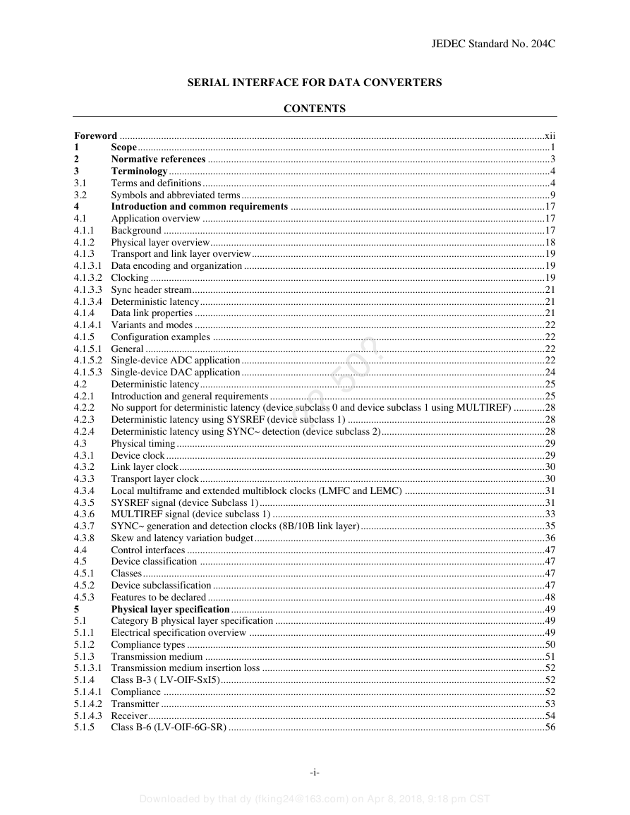
SERIAL INTERFACE FOR DATA CONVERTERS JEDEC Standard No. 204C CONTENTS ?? 50? Foreword .................................................................................................................................................................... xii Scope ............................................................................................................................................................... 1 1 Normative references .................................................................................................................................... 3 2 Terminology ................................................................................................................................................... 4 3 3.1 Terms and definitions ...................................................................................................................................... 4 Symbols and abbreviated terms ....................................................................................................................... 9 3.2 Introduction and common requirements .................................................................................................. 17 4 Application overview .................................................................................................................................... 17 4.1 Background ................................................................................................................................................... 17 4.1.1 4.1.2 Physical layer overview ................................................................................................................................. 18 4.1.3 Transport and link layer overview ................................................................................................................. 19 4.1.3.1 Data encoding and organization .................................................................................................................... 19 4.1.3.2 Clocking ........................................................................................................................................................ 19 4.1.3.3 Sync header stream ........................................................................................................................................ 21 4.1.3.4 Deterministic latency ..................................................................................................................................... 21 4.1.4 Data link properties ....................................................................................................................................... 21 4.1.4.1 Variants and modes ....................................................................................................................................... 22 4.1.5 Configuration examples ................................................................................................................................ 22 4.1.5.1 General .......................................................................................................................................................... 22 4.1.5.2 Single-device ADC application ..................................................................................................................... 22 4.1.5.3 Single-device DAC application ..................................................................................................................... 24 4.2 Deterministic latency ..................................................................................................................................... 25 4.2.1 Introduction and general requirements .......................................................................................................... 25 4.2.2 No support for deterministic latency (device subclass 0 and device subclass 1 using MULTIREF) ............ 28 4.2.3 Deterministic latency using SYSREF (device subclass 1) ............................................................................ 28 4.2.4 Deterministic latency using SYNC~ detection (device subclass 2) ............................................................... 28 4.3 Physical timing .............................................................................................................................................. 29 4.3.1 Device clock .................................................................................................................................................. 29 Link layer clock ............................................................................................................................................. 30 4.3.2 Transport layer clock ..................................................................................................................................... 30 4.3.3 4.3.4 Local multiframe and extended multiblock clocks (LMFC and LEMC) ...................................................... 31 4.3.5 SYSREF signal (device Subclass 1) .............................................................................................................. 31 4.3.6 MULTIREF signal (device subclass 1) ......................................................................................................... 33 SYNC~ generation and detection clocks (8B/10B link layer) ....................................................................... 35 4.3.7 Skew and latency variation budget ................................................................................................................ 36 4.3.8 4.4 Control interfaces .......................................................................................................................................... 47 Device classification ..................................................................................................................................... 47 4.5 4.5.1 Classes ........................................................................................................................................................... 47 4.5.2 Device subclassification ................................................................................................................................ 47 4.5.3 Features to be declared .................................................................................................................................. 48 Physical layer specification ......................................................................................................................... 49 5 Category B physical layer specification ........................................................................................................ 49 5.1 Electrical specification overview .................................................................................................................. 49 5.1.1 5.1.2 Compliance types .......................................................................................................................................... 50 5.1.3 Transmission medium ................................................................................................................................... 51 5.1.3.1 Transmission medium insertion loss ............................................................................................................. 52 5.1.4 Class B-3 ( LV-OIF-SxI5) ............................................................................................................................. 52 5.1.4.1 Compliance ................................................................................................................................................... 52 5.1.4.2 Transmitter .................................................................................................................................................... 53 5.1.4.3 Receiver ......................................................................................................................................................... 54 5.1.5 Class B-6 (LV-OIF-6G-SR) .......................................................................................................................... 56 Downloaded by that dy (fking24@163.com) on Apr 8, 2018, 9:18 pm CST -i-
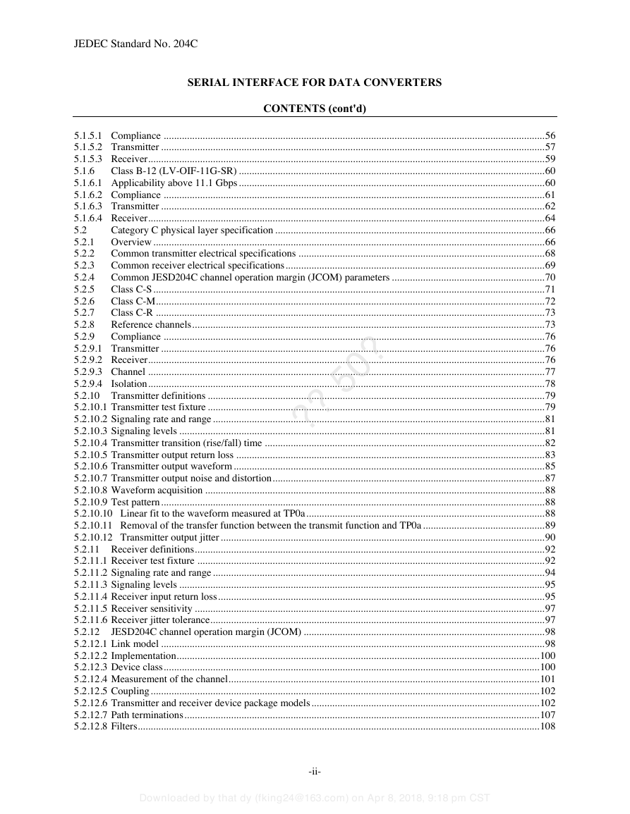
JEDEC Standard No. 204C SERIAL INTERFACE FOR DATA CONVERTERS CONTENTS (cont'd) ?? 50? 5.1.5.1 Compliance ................................................................................................................................................... 56 5.1.5.2 Transmitter .................................................................................................................................................... 57 5.1.5.3 Receiver ......................................................................................................................................................... 59 5.1.6 Class B-12 (LV-OIF-11G-SR) ...................................................................................................................... 60 5.1.6.1 Applicability above 11.1 Gbps ...................................................................................................................... 60 5.1.6.2 Compliance ................................................................................................................................................... 61 5.1.6.3 Transmitter .................................................................................................................................................... 62 5.1.6.4 Receiver ......................................................................................................................................................... 64 5.2 Category C physical layer specification ........................................................................................................ 66 5.2.1 Overview ....................................................................................................................................................... 66 Common transmitter electrical specifications ............................................................................................... 68 5.2.2 Common receiver electrical specifications .................................................................................................... 69 5.2.3 Common JESD204C channel operation margin (JCOM) parameters ........................................................... 70 5.2.4 5.2.5 Class C-S ....................................................................................................................................................... 71 Class C-M ...................................................................................................................................................... 72 5.2.6 Class C-R ...................................................................................................................................................... 73 5.2.7 Reference channels ........................................................................................................................................ 73 5.2.8 5.2.9 Compliance ................................................................................................................................................... 76 5.2.9.1 Transmitter .................................................................................................................................................... 76 5.2.9.2 Receiver ......................................................................................................................................................... 76 5.2.9.3 Channel ......................................................................................................................................................... 77 5.2.9.4 Isolation ......................................................................................................................................................... 78 5.2.10 Transmitter definitions .................................................................................................................................. 79 5.2.10.1 Transmitter test fixture .................................................................................................................................. 79 5.2.10.2 Signaling rate and range ................................................................................................................................ 81 5.2.10.3 Signaling levels ............................................................................................................................................. 81 5.2.10.4 Transmitter transition (rise/fall) time ............................................................................................................ 82 5.2.10.5 Transmitter output return loss ....................................................................................................................... 83 5.2.10.6 Transmitter output waveform ........................................................................................................................ 85 5.2.10.7 Transmitter output noise and distortion ......................................................................................................... 87 5.2.10.8 Waveform acquisition ................................................................................................................................... 88 5.2.10.9 Test pattern .................................................................................................................................................... 88 5.2.10.10 Linear fit to the waveform measured at TP0a ............................................................................................ 88 5.2.10.11 Removal of the transfer function between the transmit function and TP0a ............................................... 89 5.2.10.12 Transmitter output jitter ............................................................................................................................. 90 5.2.11 Receiver definitions ....................................................................................................................................... 92 5.2.11.1 Receiver test fixture ...................................................................................................................................... 92 5.2.11.2 Signaling rate and range ................................................................................................................................ 94 5.2.11.3 Signaling levels ............................................................................................................................................. 95 5.2.11.4 Receiver input return loss .............................................................................................................................. 95 5.2.11.5 Receiver sensitivity ....................................................................................................................................... 97 5.2.11.6 Receiver jitter tolerance ................................................................................................................................. 97 5.2.12 JESD204C channel operation margin (JCOM) ............................................................................................. 98 5.2.12.1 Link model .................................................................................................................................................... 98 5.2.12.2 Implementation ............................................................................................................................................ 100 5.2.12.3 Device class ................................................................................................................................................. 100 5.2.12.4 Measurement of the channel ........................................................................................................................ 101 5.2.12.5 Coupling ...................................................................................................................................................... 102 5.2.12.6 Transmitter and receiver device package models ........................................................................................ 102 5.2.12.7 Path terminations ......................................................................................................................................... 107 5.2.12.8 Filters........................................................................................................................................................... 108 Downloaded by that dy (fking24@163.com) on Apr 8, 2018, 9:18 pm CST -ii-
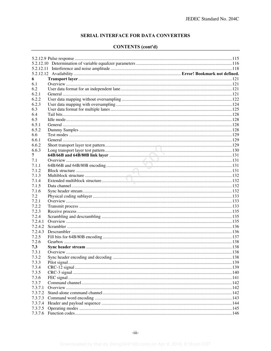
JEDEC Standard No. 204C SERIAL INTERFACE FOR DATA CONVERTERS CONTENTS (cont'd) ?? 50? 5.2.12.9 Pulse response ............................................................................................................................................. 115 5.2.12.10 Determination of variable equalizer parameters ...................................................................................... 116 5.2.12.11 Interference and noise amplitude ............................................................................................................. 118 5.2.12.12 Availability ................................................................................................ Error! Bookmark not defined. 6 Transport layer .......................................................................................................................................... 121 Overview ..................................................................................................................................................... 121 6.1 6.2 User data format for an independent lane .................................................................................................... 121 6.2.1 General ........................................................................................................................................................ 121 6.2.2 User data mapping without oversampling ................................................................................................... 122 6.2.3 User data mapping with oversampling ........................................................................................................ 124 User data format for multiple lanes ............................................................................................................. 125 6.3 Tail bits ........................................................................................................................................................ 128 6.4 6.5 Idle mode ..................................................................................................................................................... 128 6.5.1 General ........................................................................................................................................................ 128 6.5.2 Dummy Samples ......................................................................................................................................... 128 6.6 Test modes .................................................................................................................................................. 129 6.6.1 General ........................................................................................................................................................ 129 6.6.2 Short transport layer test pattern .................................................................................................................. 129 Long transport layer test pattern .................................................................................................................. 130 6.6.3 64B/66B and 64B/80B link layer .............................................................................................................. 131 7 Overview ..................................................................................................................................................... 131 7.1 7.1.1 64B/66B and 64B/80B encoding ................................................................................................................. 131 7.1.2 Block structure ............................................................................................................................................ 131 7.1.3 Multiblock structure .................................................................................................................................... 132 7.1.4 Extended multiblock structure ..................................................................................................................... 132 7.1.5 Data channel ................................................................................................................................................ 132 7.1.6 Sync header stream ...................................................................................................................................... 132 7.2 Physical coding sublayer ............................................................................................................................. 133 7.2.1 Overview ..................................................................................................................................................... 133 Transmit process ......................................................................................................................................... 133 7.2.2 7.2.3 Receive process ........................................................................................................................................... 135 7.2.4 Scrambling and descrambling ..................................................................................................................... 135 7.2.4.1 Overview ..................................................................................................................................................... 135 7.2.4.2 Scrambler .................................................................................................................................................... 136 7.2.4.3 Descrambler ................................................................................................................................................ 136 7.2.5 Fill bits for 64B/80B encoding .................................................................................................................... 137 7.2.6 Gearbox ....................................................................................................................................................... 138 7.3 Sync header stream ................................................................................................................................... 138 7.3.1 Overview ..................................................................................................................................................... 138 7.3.2 Sync header encoding and decoding ........................................................................................................... 138 Pilot signal ................................................................................................................................................... 139 7.3.3 CRC-12 signal ............................................................................................................................................. 139 7.3.4 CRC-3 signal ............................................................................................................................................... 140 7.3.5 7.3.6 FEC signal ................................................................................................................................................... 141 7.3.7 Command channel ....................................................................................................................................... 142 7.3.7.1 Overview ..................................................................................................................................................... 142 7.3.7.2 Stand-alone command channel .................................................................................................................... 142 7.3.7.3 Command word encoding ........................................................................................................................... 143 7.3.7.4 Header and payload sequence ..................................................................................................................... 144 7.3.7.5 Operating modes ......................................................................................................................................... 145 7.3.7.6 Function codes............................................................................................................................................. 146 Downloaded by that dy (fking24@163.com) on Apr 8, 2018, 9:18 pm CST -iii-
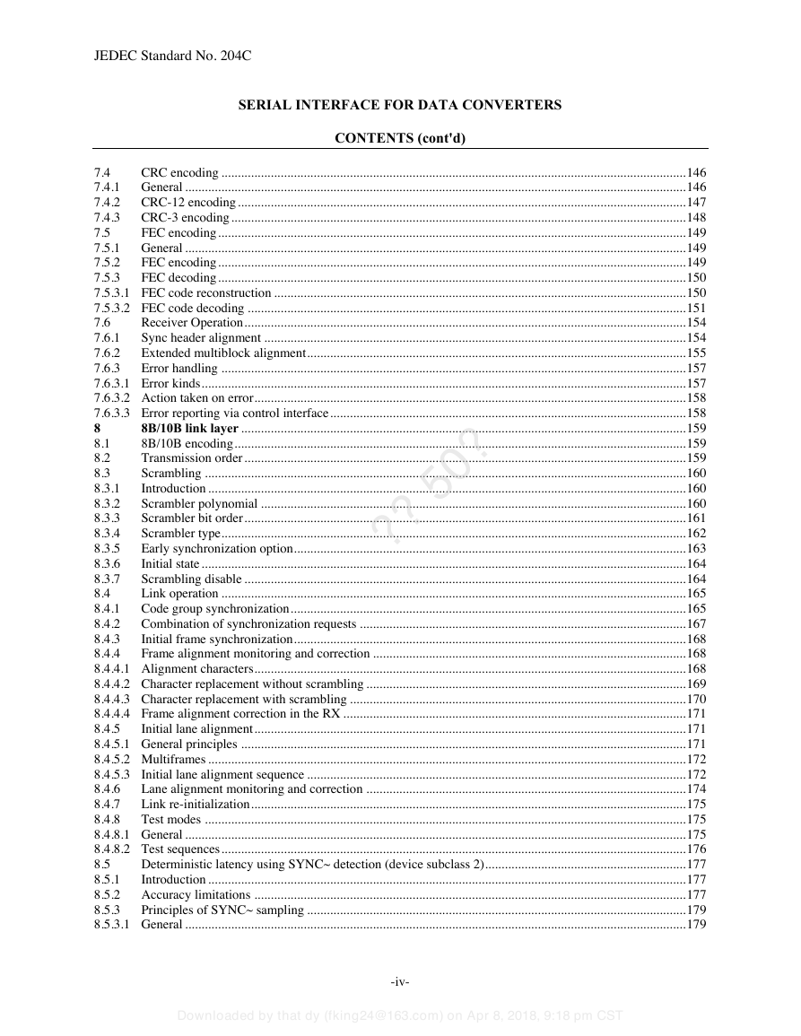
JEDEC Standard No. 204C SERIAL INTERFACE FOR DATA CONVERTERS CONTENTS (cont'd) ?? 50? 7.4 CRC encoding ............................................................................................................................................. 146 7.4.1 General ........................................................................................................................................................ 146 CRC-12 encoding ........................................................................................................................................ 147 7.4.2 CRC-3 encoding .......................................................................................................................................... 148 7.4.3 7.5 FEC encoding .............................................................................................................................................. 149 7.5.1 General ........................................................................................................................................................ 149 FEC encoding .............................................................................................................................................. 149 7.5.2 7.5.3 FEC decoding .............................................................................................................................................. 150 7.5.3.1 FEC code reconstruction ............................................................................................................................. 150 7.5.3.2 FEC code decoding ..................................................................................................................................... 151 Receiver Operation ...................................................................................................................................... 154 7.6 Sync header alignment ................................................................................................................................ 154 7.6.1 7.6.2 Extended multiblock alignment ................................................................................................................... 155 7.6.3 Error handling ............................................................................................................................................. 157 7.6.3.1 Error kinds ................................................................................................................................................... 157 7.6.3.2 Action taken on error ................................................................................................................................... 158 7.6.3.3 Error reporting via control interface ............................................................................................................ 158 8 8B/10B link layer ....................................................................................................................................... 159 8B/10B encoding ......................................................................................................................................... 159 8.1 Transmission order ...................................................................................................................................... 159 8.2 Scrambling .................................................................................................................................................. 160 8.3 Introduction ................................................................................................................................................. 160 8.3.1 8.3.2 Scrambler polynomial ................................................................................................................................. 160 Scrambler bit order ...................................................................................................................................... 161 8.3.3 Scrambler type ............................................................................................................................................. 162 8.3.4 Early synchronization option ....................................................................................................................... 163 8.3.5 8.3.6 Initial state ................................................................................................................................................... 164 Scrambling disable ...................................................................................................................................... 164 8.3.7 Link operation ............................................................................................................................................. 165 8.4 Code group synchronization ........................................................................................................................ 165 8.4.1 8.4.2 Combination of synchronization requests ................................................................................................... 167 Initial frame synchronization ....................................................................................................................... 168 8.4.3 8.4.4 Frame alignment monitoring and correction ............................................................................................... 168 8.4.4.1 Alignment characters ................................................................................................................................... 168 8.4.4.2 Character replacement without scrambling ................................................................................................. 169 8.4.4.3 Character replacement with scrambling ...................................................................................................... 170 8.4.4.4 Frame alignment correction in the RX ........................................................................................................ 171 8.4.5 Initial lane alignment ................................................................................................................................... 171 8.4.5.1 General principles ....................................................................................................................................... 171 8.4.5.2 Multiframes ................................................................................................................................................. 172 8.4.5.3 Initial lane alignment sequence ................................................................................................................... 172 Lane alignment monitoring and correction ................................................................................................. 174 8.4.6 Link re-initialization .................................................................................................................................... 175 8.4.7 8.4.8 Test modes .................................................................................................................................................. 175 8.4.8.1 General ........................................................................................................................................................ 175 8.4.8.2 Test sequences ............................................................................................................................................. 176 Deterministic latency using SYNC~ detection (device subclass 2) ............................................................. 177 8.5 8.5.1 Introduction ................................................................................................................................................. 177 8.5.2 Accuracy limitations ................................................................................................................................... 177 8.5.3 Principles of SYNC~ sampling ................................................................................................................... 179 8.5.3.1 General ........................................................................................................................................................ 179 Downloaded by that dy (fking24@163.com) on Apr 8, 2018, 9:18 pm CST -iv-
分享到:
收藏