10
15
20
25
30
35
中国科技论文在线
http://www.paper.edu.cn
Internal Fault Diagnosis of
Permanent Magnet Synchronous Generator#
Fang Hongwei*
(School of Electrical Engineering and Automation,Tianjin University,Tianjin, 300072)
Abstract: A coupled field-circuit method by taking into account the saturation is proposed in this paper.
The stator winding inter-turn short circuit and the rotor eccentricity hybrid fault of permanent magnet
synchronous generators (PMSG) is analyzed. The harmonic currents were used in order to investigate
this kind of fault in a 7.5 kVA PMSG suitable for low-power wind generation applications. Simulation
results have shown that the sideband frequency currents at 25 Hz and 75 Hz, and the 17th and 19th
order components of terminal currents can be used as fault detection criteria.
Key words: Permanent magnet synchronous generator; inter-turn short circuit fault; rotor eccentricity;
coupled fieldcircuit
0 Introduction
Along with the development of renewable energy and electrical power industry, diagnostics
and monitoring of the internal faults of wind generators has attracted greater research attention [1,
2]. Permanent magnetic synchronous generator (PMSG) and doubly-fed induction generators
(DFIG) are the most widely used in variable-speed wind turbines at present. PMSG is increasingly
finding its applications in wind power generation because of its outstanding advantages such as
simple structure, high efficiency, small size and easy control [3-6]. In addition, there is a clear
tendency to use this kind of generators with a full-rate converter. However, stator winding faults
of PMSG, which occur due to a combination of thermal, electrical, mechanical and environmental
stresses that act on the stator, are found to be one of the major causes of machine failure. Accurate
diagnosis and protection for this kind of fault can play a vital role in reducing the unnecessary
production downtime and enhancing the reliability of wind power system, which leads to a cost
effective generator operation. In the meantime, rotor eccentricities detection and fault severity
assessment in electrical machines have regained increased interests for many researchers [7-12]. If
the air gap eccentricity is large, then the resulting unbalanced radial forces can cause rotor to stator
rub. This can result in the damage of the stator core and stator winding. Notice that the inter-turn
short circuit probably leads to a vibration or eccentricity in generator too. In order to overcome
these problems, this paper aims to study the hybrid fault, namely the inter-turn short circuit and
the rotor eccentricity. Furthermore, it is our worth to enhance the detection accuracy for this kind
hybrid fault in PMSG, proper harmonic currents, such as the sideband frequency current at 25 Hz
and 75 Hz, the 17th and 19th order currents, are selected to be the fault detection criteria. The finite
element (FE) model for PMSG was presented. The common methods employed to model and
detect the inter-turn short circuit and eccentricity fault are described. The hybrid fault is analyzed
by the coupled field-circuit method and FFT technique.
Foundations: Ph.D. Programs Foundation of Ministry of Education of China (No. 20090032120078).
Brief author introduction:Fang Hongwei(1977-), Male, Associate Professor, Main research: Electrical machine and
its control. E-mail: hongwei_fang@tju.edu.cn
- 1 -
�
40
45
50
55
60
65
70
中国科技论文在线
http://www.paper.edu.cn
1 Modeling of Inter-turn short circuit and eccentricity with couple
field-circuit
Many references have addressed the principles of how a wind turbine works [13-15]. Although, there
are many models that have been derived for the PMSG wind turbine, all of them have slightly
differences. Based on these papers, the wind turbine power can be expressed as
CP
=
p
(
,
)
βλ
3
w
=
C
p
(
,
)
βλ
Avρ
2
vRρ
π
2
32
w
(1)
where Cp is the performance coefficient, λ is the tip speed ratio, β is the blade pitch angle, A is the
effective air volume flow in the rotor area, ρ is the air density, and vw is the wind speed.
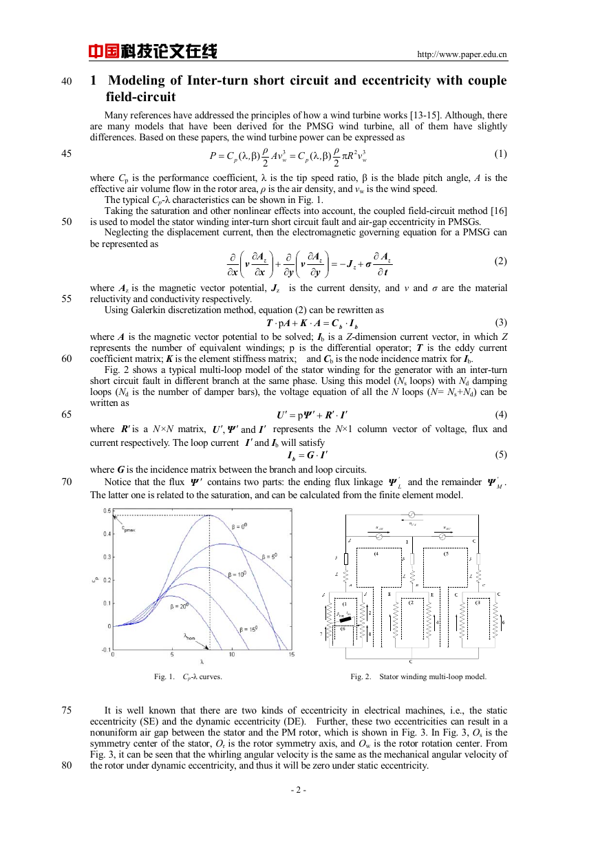
The typical Cp-λ characteristics can be shown in Fig. 1.
Taking the saturation and other nonlinear effects into account, the coupled field-circuit method [16]
is used to model the stator winding inter-turn short circuit fault and air-gap eccentricity in PMSGs.
Neglecting the displacement current, then the electromagnetic governing equation for a PMSG can
be represented as
∂
x
∂
⎛
⎜⎜
⎝
v
A
∂
z
x
∂
⎞
+⎟⎟
⎠
∂
y
∂
⎛
⎜⎜
⎝
v
A
∂
z
y
∂
⎞
−=⎟⎟
⎠
J
z
+
σ
z
A
∂
t
∂
(2)
where Az is the magnetic vector potential, Jz is the current density, and v and σ are the material
reluctivity and conductivity respectively.
Using Galerkin discretization method, equation (2) can be rewritten as
b
+
⋅p
=⋅
b ICAKAT
⋅
(3)
where A is the magnetic vector potential to be solved; Ib is a Z-dimension current vector, in which Z
represents the number of equivalent windings; p is the differential operator; T is the eddy current
coefficient matrix; K is the element stiffness matrix; and Cb is the node incidence matrix for Ib.
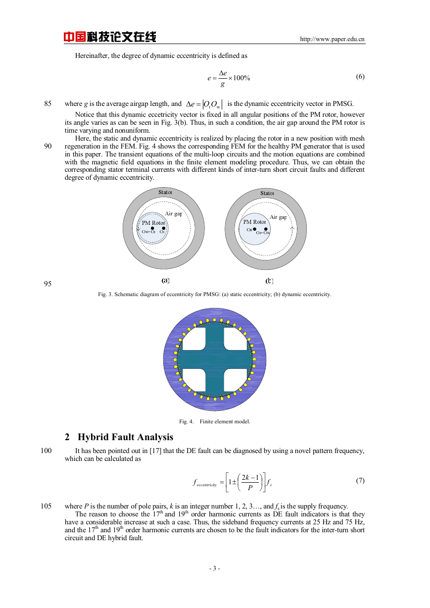
Fig. 2 shows a typical multi-loop model of the stator winding for the generator with an inter-turn
short circuit fault in different branch at the same phase. Using this model (Ns loops) with Nd damping
loops (Nd is the number of damper bars), the voltage equation of all the N loops (N= Ns+Nd) can be
written as
(4)
represents the N×1 column vector of voltage, flux and
IRΨ
p
⋅′+′
=′
U
′
where R′is a N×N matrix,
current respectively. The loop current I′ and Ib will satisfy
IG
′
⋅
ΨU
and
=
,
′
I
′
′
Ib
(5)
where G is the incidence matrix between the branch and loop circuits.
Notice that the flux Ψ ′ contains two parts: the ending flux linkage
The latter one is related to the saturation, and can be calculated from the finite element model.
'
LΨ and the remainder
BAu ′
′
ACu ′
′
CBu ′
′
KLi
'
MΨ .
Fig. 1. Cp-λ curves. Fig. 2. Stator winding multi-loop model.
75
80
It is well known that there are two kinds of eccentricity in electrical machines, i.e., the static
eccentricity (SE) and the dynamic eccentricity (DE). Further, these two eccentricities can result in a
nonuniform air gap between the stator and the PM rotor, which is shown in Fig. 3. In Fig. 3, Os is the
symmetry center of the stator, Or is the rotor symmetry axis, and Ow is the rotor rotation center. From
Fig. 3, it can be seen that the whirling angular velocity is the same as the mechanical angular velocity of
the rotor under dynamic eccentricity, and thus it will be zero under static eccentricity.
- 2 -
�
85
where g is the average airgap length, and
wrOOe =Δ
is the dynamic eccentricity vector in PMSG.
中国科技论文在线
http://www.paper.edu.cn
Hereinafter, the degree of dynamic eccentricity is defined as
e
%100×Δ=
e
g
(6)
Notice that this dynamic eccetricity vector is fixed in all angular positions of the PM rotor, however
its angle varies as can be seen in Fig. 3(b). Thus, in such a condition, the air gap around the PM rotor is
time varying and nonuniform.
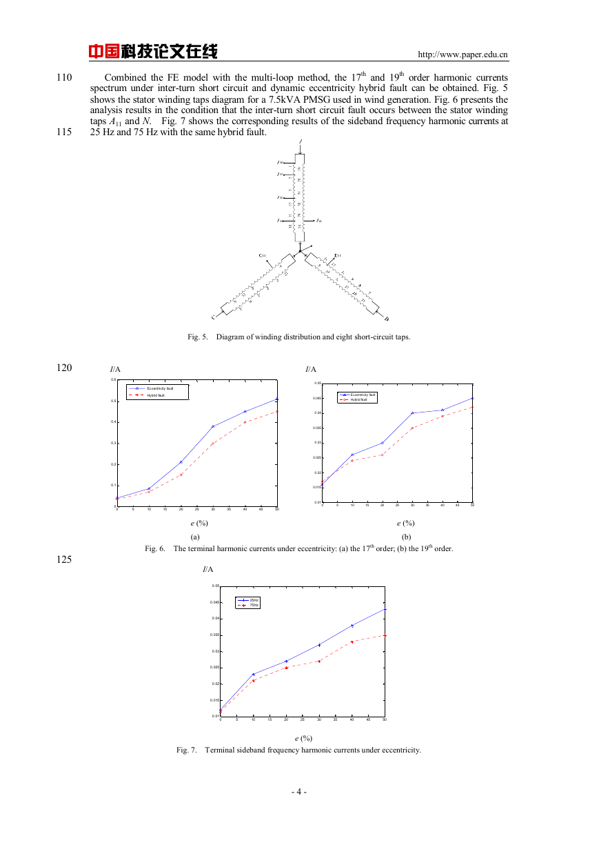
Here, the static and dynamic eccentricity is realized by placing the rotor in a new position with mesh
regeneration in the FEM. Fig. 4 shows the corresponding FEM for the healthy PM generator that is used
in this paper. The transient equations of the multi-loop circuits and the motion equations are combined
with the magnetic field equations in the finite element modeling procedure. Thus, we can obtain the
corresponding stator terminal currents with different kinds of inter-turn short circuit faults and different
degree of dynamic eccentricity.
90
95
100
105
Fig. 3. Schematic diagram of eccentricity for PMSG: (a) static eccentricity; (b) dynamic eccentricity.
Fig. 4. Finite element model.
2 Hybrid Fault Analysis
It has been pointed out in [17] that the DE fault can be diagnosed by using a novel pattern frequency,
which can be calculated as
f
eccentrici
ty
=
(7)
f
s
±
⎡
1
⎢
⎣
1
2
k
−
P
⎛
⎜
⎝
⎞
⎟
⎠
⎤
⎥
⎦
where P is the number of pole pairs, k is an integer number 1, 2, 3…, and fs is the supply frequency.
The reason to choose the 17th and 19th order harmonic currents as DE fault indicators is that they
have a considerable increase at such a case. Thus, the sideband frequency currents at 25 Hz and 75 Hz,
and the 17th and 19th order harmonic currents are chosen to be the fault indicators for the inter-turn short
circuit and DE hybrid fault.
- 3 -
�
中国科技论文在线
http://www.paper.edu.cn
110
115
Combined the FE model with the multi-loop method, the 17th and 19th order harmonic currents
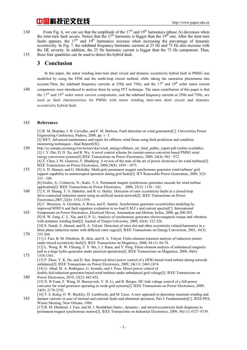
spectrum under inter-turn short circuit and dynamic eccentricity hybrid fault can be obtained. Fig. 5
shows the stator winding taps diagram for a 7.5kVA PMSG used in wind generation. Fig. 6 presents the
analysis results in the condition that the inter-turn short circuit fault occurs between the stator winding
taps A11 and N. Fig. 7 shows the corresponding results of the sideband frequency harmonic currents at
25 Hz and 75 Hz with the same hybrid fault.
120
125
-4
-22
32
31
14
Fig. 5. Diagram of winding distribution and eight short-circuit taps.
I/A I/A
0.6
0.5
0.4
0.3
0.2
0.1
0
0
Eccentricity fault
Hybrid fault
5
10
15
20
25
30
35
40
45
50
0.05
0.045
0.04
0.035
0.03
0.025
0.02
0.015
0.01
0
Eccentricity fault
Hybrid fault
5
10
15
20
25
30
35
40
45
50
e (%) e (%)
(a) (b)
Fig. 6. The terminal harmonic currents under eccentricity: (a) the 17th order; (b) the 19th order.
I/A
0.05
0.045
0.04
0.035
0.03
0.025
0.02
0.015
0.01
0
25Hz
75Hz
5
10
15
20
25
30
35
40
45
50
e (%)
Fig. 7. Terminal sideband frequency harmonic currents under eccentricity.
- 4 -
�
130
135
140
中国科技论文在线
http://www.paper.edu.cn
From Fig. 6, we can see that the amplitude of the 17th and 19th harmonics (phase A) decreases when
the inter-turn fault occurs. Notice that the 17th harmonic is bigger than the 19th one. After the inter-turn
faults appears, the 17th and 19th harmonics increase when increasing the percentage of dynamic
eccentricity. In Fig. 7, the sideband frequency harmonic currents at 25 Hz and 75 Hz also increase with
the DE severity. In addition, the 25 Hz harmonic current is bigger than the 75 Hz component. Thus,
these four quantities can be used to detect the hybrid fault.
3 Conclusion
In this paper, the stator winding inter-turn short circuit and dynamic eccentricity hybrid fault in PMSG was
modelled by using the FEM and the multi-loop circuit method, while taking the saturation phenomena into
account.Then, the sideband frequency currents at 25Hz and 75Hz, and the 17th and 19th order stator current
components were introduced to analyze them by using FFT technique. The main contribution of this paper is that
the 17th and 19th order stator current components, and the sideband frequency currents at 25Hz and 75Hz, are
used as fault characteristics for PMSG with stator winding inter-turn short circuit and dynamic
eccentricity hybrid fault.
145
References
150
155
160
165
170
175
180
185
[1] R. M. Brandao, J. B. Carvalho, and F. M. Barbosa. Fault detection on wind generators[C]. Universities Power
Engineering Conference, Padova, 2008. pp. 1- 5.
[2] ISET. Advanced maintenance and repair for offshore wind farms using fault prediction and condition
monitoring techniques - final Report[OL].
http://ec.europa.eu/energy/res/sectors/doc/wind_energy/offshore_mr_final_public_report.pdf (online available).
[3] J. Y. Dai; D. D. Xu, and B. Wu. A novel control scheme for current-source-converter-based PMSG wind
energy conversion systems[J] IEEE Transactions on Power Electronics, 2009, 24(4): 963 - 972.
[4] Z. Chen, J. M. Guerrero, F. Blaabjerg. A review of the state of the art of power electronics for wind turbines[J].
IEEE Transactions on Power Electronics, 2009,24(8): 1859 - 1875.
[5] A. D. Hansen, and G. Michalke. Multi-pole permanent magnet synchronous generator wind turbines' grid
support capability in uninterrupted operation during grid faults[J]. IET Renewable Power Generation, 2009, 3(3):
333 - 348.
[6] Grabic, S.; Celanovic, N.; Katic, V.A. Permanent magnet synchronous generator cascade for wind turbine
application[J]. IEEE Transactions on Power Electronics, 2008, 23(3): 1136 - 142.
[7] X. H. Huang, T. G. Habetler, and R. G. Harley. Detection of rotor eccentricity faults in a closed-loop
drive-connected induction motor using an artificial neural network[J]. IEEE Transactions on Power
Electronics,2007,22(4): 1552-1559.
[8] C. Bruzzese, A. Giordani, A. Rossi, and E. Santini. Synchronous generator eccentricities modeling by
improved MWFA and fault signature evaluation in no-load E.M.F.s and current spectra[C]. International
Symposium on Power Electronics, Electrical Drives, Automation and Motion, Ischia, 2008, pp.200-205.
[9] H. W. Fang, C. L. Xia, and G. P. Li. Analysis of synchronous generator electro-magnetic torque and vibration
with armature winding fault[J]. Journal of Tianjin University, 2009, 42(4): 322-326.
[10] S. Nandi, S. Ahmed, and H. A. Toliyat. Detection of rotor slot and other eccentricity related harmonics in a
three phase induction motor with different rotor cages[J]. IEEE Transactions on Energy Conversion, 2001, 16(3):
253-260.
[11] J. Faiz, B. M. Ebrahimi, B. Akin, and H. A. Toliyat. Finite-element transient analysis of induction motors
under mixed eccentricity fault[J]. IEEE Transactions on Magnetics, 2008, 44 (1): 66-74.
[12] L. Wang, R. W. Cheung, Z. Y. Ma, J. J. Ruan, and Y. Peng. Finite-element analysis of unbalanced magnetic
pull in a large hydro-generator under practical operations[J]. IEEE Transactions on Magnetics, 2008, 44(6):
1558-1561.
[13] P. Zhou, Y. K. He, and D. Sun. Improved direct power control of a DFIG-based wind turbine during network
unbalance[J]. IEEE Transactions on Power Electronics, 2009, 24(11): 2465-2474.
[14] G. Abad, M. A. Rodriguez, G. Iwanski, and J. Poza. Direct power control of
doubly-fed-induction-generator-based wind turbines under unbalanced grid voltage[J]. IEEE Transactions on
Power Electronics, 2010, 25(2): 442-452.
[15] X. B Yuan, F. Wang, D. Boroyevich, Y. D. Li, and R. Burgos. DC-link voltage control of a full power
converter for wind generator operating in weak-grid systems[J]. IEEE Transactions on Power Electronics, 2009,
24(9): 2178-2192.
[16] T. S. Kulig, O. W. Buckley, D. Lambrecht, and M. Liese. A new approach to determine transient winding and
damper currents in case of internal and external faults and abnormal operation, Part I: Fundamentals[C]. IEEE/PES,
Winter Meeting, New Orleans, 1986.
[17] B. M. Ebrahimi, J. Faiz, and M. J. Roshtkhari.Static-, dynamic-, and mixed-eccentricity fault diagnoses in
permanent-magnet synchronous motors[J]. IEEE Transactoins on Industrial Electronics, 2009, 56(11): 4727–4739.
- 5 -
�
中国科技论文在线
http://www.paper.edu.cn
190
永磁同步电机内部故障分析
(天津大学电气与自动化工程学院,天津市 南开区 300072)
方红伟
摘要:提出了一种考虑饱和现象的磁路耦合分析法,分析了永磁同步发电机的定子绕组匝间
短路和转子偏心综合故障。谐波电流被用以分析一台 7.5kVA 的低功率永磁同步风力发电机。
仿真结果表面,边频 25Hz、75Hz 频段的谐波电流和 17 阶、19 阶的谐波电流可以作为该类
故障的诊断判据。
关键词:永磁同步电机;匝间短路故障;转子偏心;场路耦合
中图分类号:TM614
195
200
- 6 -
�



 2023年江西萍乡中考道德与法治真题及答案.doc
 2012年重庆南川中考生物真题及答案.doc
 2013年江西师范大学地理学综合及文艺理论基础考研真题.doc
 2020年四川甘孜小升初语文真题及答案I卷.doc
 2020年注册岩土工程师专业基础考试真题及答案.doc
 2023-2024学年福建省厦门市九年级上学期数学月考试题及答案.doc
 2021-2022学年辽宁省沈阳市大东区九年级上学期语文期末试题及答案.doc
 2022-2023学年北京东城区初三第一学期物理期末试卷及答案.doc
 2018上半年江西教师资格初中地理学科知识与教学能力真题及答案.doc
 2012年河北国家公务员申论考试真题及答案-省级.doc
 2020-2021学年江苏省扬州市江都区邵樊片九年级上学期数学第一次质量检测试题及答案.doc
 2022下半年黑龙江教师资格证中学综合素质真题及答案.doc