XAPP1026 (v3.2)
October 28, 2012
Summary
Included
Systems
Hardware and
Software
Requirements
Introduction
Application Note: Embedded Processing
LightWeight IP (lwIP) Application Examples
Author: Anirudha Sarangi and Stephen MacMahon
Lightweight IP (lwIP) is an open source TCP/IP networking stack for embedded systems. The
Xilinx Software Development Kit (SDK) provides lwIP software customized to run on various
Xilinx embedded systems that can be MicroBlaze™ or PowerPC® processor based. The Xilinx
SDK provided lwIP software can also be run on ARM® based Xilinx Zynq™ SoC systems.The
information in this application notes applies to MicroBlaze processors and ARM-based Zynq
SoC systems. This application note describes how to utilize the lwIP library to add networking
capability to an embedded system. In particular, lwIP is utilized to develop these applications:
echo server, Web server, TFTP server and receive and transmit throughput tests.
Included with this application note are AXI4-based reference systems for the Xilinx ML605 and
SP605 FPGA Starter Kit boards. Also included are Zynq SoC reference systems for the Xilinx
ZC-702 boards. To access these reference systems, click the following link.
https://secure.xilinx.com/webreg/clickthrough.do?cid=107743.zip
The hardware and software requirements are:
One of the Xilinx ML605, or SP605 for MicroBlaze processor based systems and a
ZC-702 board for Zynq SoC-based systems.
Xilinx Platform USB cable for MicroBlaze pr ocessor-based systems and Xilinx JTAG for
Zynq SoC based systems
USB cable for RS232 UART communication on the board
An ethernet cable connecting the board to a Windows or Linux host
Serial Communications Utility Program, such as HyperTerminal or Teraterm
Xilinx Platform Studio 14.3 for making hardware modifications
Xilinx SDK 14.3 for running or maki ng modifications to the software
lwIP is an open source networking stack designed for embedded systems. It is provided under
a BSD style license. The objective of this application note is to describe how to use lwIP
shipped along with the Xilinx SDK to add networking capability to an embedded system. In
particular, this application note describes how applications such as an echo server or a Web
server can be written using lwIP.
The lwIP library released as part of 14.3 and used in the reference designs use the open
source lwIP version lwip 1.4.0.
© Copyright 2008–2012 Xilinx, Inc. Xilinx, the Xilinx logo, Artix, ISE, Kintex, Spartan, Virtex, Vivado, Zynq, and other designated brands included herein are trademarks of Xilinx
in the United States and other countries. ARM is a registered trademark of ARM in the EU and other countries. The PowerPC name and logo are registered trademarks of IBM
Corp. and used under license. All other trademarks are the property of their respective owners.
XAPP1026 (v3.2) October 28, 2012
www.xilinx.com
1
�
Reference
System
Specifics
The reference design for this application note is structured as follows:
ml605_AxiEth_8Kb_Cache, ml605_AxiEth_32kb_Cache,
sp605_AxiEth_8kb_Cache, sp605_AxiEth_32kb_Cache,
sp605_EthernetLite_8kb_Cache, sp605_EthernetLite_32kb_Cache, and
zc702_GigE folders correspond to the various supported boards and hardware designs.
In each of these folders, the hw subdirectory contains the XPS hardware design, and the
sw subdirectory contains the application software and software platforms that need to be
imported into SDK.
There is a folder with the name 13_1, which contains the older designs released in the
previous version of xapp1026 and which were tested with the 13.1 release. These designs
are provided for easy reference. This document does not discuss these older designs
anywhere in the subsequent sections.
The ready_for_download folder contains these relevant files for getting started with the
applications:
download.bit: bitstream to be downloaded to the board. Applicable only for
MicroBlaze processor based systems.
system_bd.bmm: for downloading the bitstream. Applicable only for MicroBlaze
processor-based systems.
image.mfs: memory file system used for tftp, Web server applications
image_BIG.mfs: provided only in the ready_for_download folder for the
zc702_GigE hardware system. This is a large mfs file that can be used for Zynq
device web server applications and shows the high-speed performance of Zynq
devices.
raw_apps.elf: application ELF image to be downloaded to test the RAW API
socket_apps.elf: application ELF image to be downloaded to test the socket API
fsbl.elf: first stage boot loader applicable only for Zynq SoC systems to initialize
the MIOs/Clocks.
The memfs folder contains the contents of the memory file system (MFS) image.
The image itself is also present as the image.mfs file in the respective
ready_for_download folders. For Zynq devices, two mfs files are provided. The
standard image.mfs (common for all boards) is present along with a large mfs file
(image_BIG.mfs) that contains huge web page contents. However, memfs contents for
this image_BIG.mfs is not provided.
A repo folder is provided for Zynq SoC systems ( zc702_GigE folder) that contains the
FreeRTOS BSP based out of latest standalone BSP v3_07_a.
XAPP1026 (v3.2) October 28, 2012
www.xilinx.com
2
�
Software
Applications
Hardware Systems
The hardware systems for the available boards were built using Base System Builder (BSB),
with minor modifications in XPS. For more information on hardware requirements for lwIP, see
the lwIP documentation available as part of the SDK installation. Table 1 provides a summary
of the hardware designs for the available boards.
Table 1: Hardware Design Details
Hardware Design Name
Processor
Processor
Frequency
Ethernet
Controller
ml605_AxiEth_8Kb_Cache
MICROBLAZE
100 MHz
axi_ethernet
ml605_AxiEth_32kb_Cache
MICROBLAZE
100 MHz
axi_ethernet
sp605_AxiEth_8kb_Cache
MICROBLAZE
100 MHz
axi_ethernet
sp605_AxiEth_32kb_Cache
MICROBLAZE
100 MHz
axi_ethernet
DMA
axi_dma
axi_dma
axi_dma
axi_dma
sp605_EthernetLite_8kb_Cache
MICROBLAZE
75 MHz
axi_ethernetlite NONE
sp605_EthernetLite_32kb_Cache MICROBLAZE
75 MHz
axi_ethernetlite NONE
zc702_GigE
Cortex-A9
666.667 MHz GigE
In-built
Notes:
1. All axi_ethernet based systems are built with full checksum (both TCP and IP checksums) offload feature.
2.
The AXI Ethernetlite based systems are built with PING-PONG buffers (one more buffer for both TX and RX
paths to improve performance).
The GigE based systems (Zynq devices) has in-built TCP/IP checksum offload support.
3.
The reference design includes these software applications:
Echo server
Web server
TFTP server
TCP RX throughput test
TCP TX throughput test
All of these applications are available in both RAW and socket modes.
Echo Server
The echo server is a simple program that echoes input that is sent to the program via the
network. This application provides a good starting point for investigating how to write lwIP
applications.
The socket mode echo server is structured as follows:
1. A main thread listens continually on a specified echo server port.
2. For each connection request, it spawns a separate echo service thread.
3.
It then continues listening on the echo port.
while (1) {
new_sd = lwip_accept(sock, (struct sockaddr *)&remote, &size);
sys_thread_new(process_echo_request, (void*)new_sd,
DEFAULT_THREAD_PRIO);
}
XAPP1026 (v3.2) October 28, 2012
www.xilinx.com
3
�
The echo service thread receives a new socket descriptor as its input on which it can read
received data. This thread does the actual echoing of the input to the originator.
while (1) {
/* read a max of RECV_BUF_SIZE bytes from socket */
n = lwip_read(sd, recv_buf, RECV_BUF_SIZE));
/* handle request */
nwrote = lwip_write(sd, recv_buf, n));
}
Note: These code snippets are not complete and are intended to show the major structure of the code
only.
The socket mode provides a simple API that blocks on socket reads and writes until they are
complete. However, the socket API requires many pieces to achieve this, including primarily a
simple multi-threaded kernel (xilkernel for MicroBlaze processor based systems and
FreeRTOS for Zynq systems). Because this API contains significant overhead for all
operations, it is slow.
The RAW API provides a callback style interface to the application. Applications using the RAW
API register callback functions to be called on significant events like accept, read or write. A
RAW API based echo server is single threaded, and all the work is done in the callback
functions. The main application loop is structured as follows:
while (1) {
if (TcpFastTmrFlag) {
tcp_fasttmr();
TcpFastTmrFlag = 0;
}
if (TcpSlowTmrFlag) {
tcp_slowtmr();
TcpSlowTmrFlag = 0;
}
xemacif_input(netif);
transfer_data();
}
The TcpFastTmrFlag and TcpSlowTmrFlag are required for TCP TX handling and are set in the
Timer handler for every 250 milliseconds and 500 milliseconds respectively.
The function of the application loop is to receive packets constantly (xemacif_input), then
pass them on to lwIP. Before entering this loop, the echo server sets up certain callbacks:
/* create new TCP PCB structure */
pcb = tcp_new();
/* bind to specified @port */
err = tcp_bind(pcb, IP_ADDR_ANY, port);
/* we do not need any arguments to callback functions */
tcp_arg(pcb, NULL);
/* listen for connections */
pcb = tcp_listen(pcb);
/* specify callback to use for incoming connections */
tcp_accept(pcb, accept_callback);
XAPP1026 (v3.2) October 28, 2012
www.xilinx.com
4
�
This sequence of calls creates a TCP connection and sets up a callback on a connection being
accepted. When a connection request is accepted, the function accept_callback is called
asynchronously. Because an echo server needs to respond only when data is received, the
accept callback function sets up the receive callback by performing:
/* set the receive callback for this connection */
tcp_recv(newpcb, recv_callback);
When a packet is received, the function recv_callback is called. The function then echoes
the data it receives back to the sender:
/* indicate that the packet has been received */
tcp_recved(tpcb, p->len);
/* echo back the payload */
err = tcp_write(tpcb, p->payload, p->len, 1);
Although the RAW API is more complex than the socket API, it provides much higher
throughput because it does not have a high overhead.
Web Server
A simple Web server implementation is provided as a reference for a TCP based application.
The Web server implements only a subset of the HTTP 1.1 protocol. Such a Web server can be
used to control or monitor an embedded platform via a browser. The Web server demonstrates
these features:
Accessing files residing on a Memory File System via HTTP GET commands
Controlling the LED lights on the development board using the HTTP POST command
Obtaining status of DIP switches on the development board using the HTTP POST
command
The Xilinx Memory File System (xilmfs) is used to store a set of files in the memory of the
development board. These files can then be accessed via an HTTP GET command by pointing
a Web browser to the IP address of the development board and requesting specific files.
Controlling or monitoring the status of components in the board is done by issuing POST
commands to a set of URLs that map to devices. When the Web server receives a POST
command to a URL that it recognizes, it calls a specific function to do the work that has been
requested. The output of this function is sent back to the Web browser in Javascript Object
Notation (JSON) format. The Web browser then interprets the data received and updates its
display.
The overall structure of the Web server is similar to the echo server – there is one main thread
which listens on the HTTP port (80) for incoming connections. For every incoming connection,
a new thread is spawned that processes the request on that connection.
The http thread first reads the request, identifies if it is a GET or a POST operation, then
performs the appropriate operation. For a GET request, the thread looks for a specific file in the
memory file system. If this file is present, it is returned to the Web browser initiating the request.
If it is not available, a HTTP 404 error code is sent back to the browser.
In socket mode, the http thread is structured as follows:
/* read in the request */
if ((read_len = read(sd, recv_buf, RECV_BUF_SIZE)) < 0)
return;
/* respond to request */
generate_response(sd, recv_buf, read_len);
XAPP1026 (v3.2) October 28, 2012
www.xilinx.com
5
�
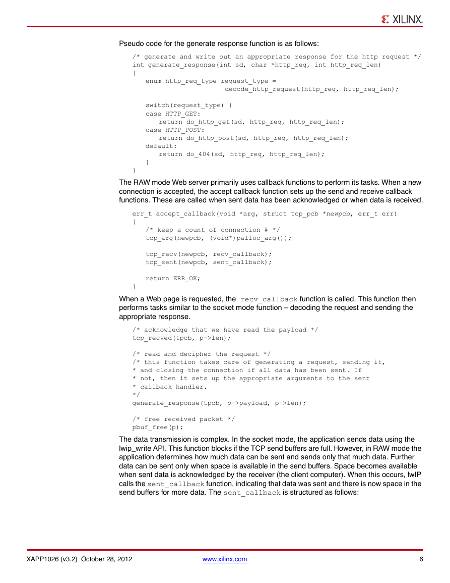
Pseudo code for the generate response function is as follows:
/* generate and write out an appropriate response for the http request */
int generate_response(int sd, char *http_req, int http_req_len)
{
enum http_req_type request_type =
decode_http_request(http_req, http_req_len);
switch(request_type) {
case HTTP_GET:
return do_http_get(sd, http_req, http_req_len);
case HTTP_POST:
return do_http_post(sd, http_req, http_req_len);
default:
return do_404(sd, http_req, http_req_len);
}
}
The RAW mode Web server primarily uses callback functions to perform its tasks. When a new
connection is accepted, the accept callback function sets up the send and receive callback
functions. These are called when sent data has been acknowledged or when data is received.
err_t accept_callback(void *arg, struct tcp_pcb *newpcb, err_t err)
{
/* keep a count of connection # */
tcp_arg(newpcb, (void*)palloc_arg());
tcp_recv(newpcb, recv_callback);
tcp_sent(newpcb, sent_callback);
return ERR_OK;
}
When a Web page is requested, the recv_callback function is called. This function then
performs tasks similar to the socket mode function – decoding the request and sending the
appropriate response.
/* acknowledge that we have read the payload */
tcp_recved(tpcb, p->len);
/* read and decipher the request */
/* this function takes care of generating a request, sending it,
* and closing the connection if all data has been sent. If
* not, then it sets up the appropriate arguments to the sent
* callback handler.
*/
generate_response(tpcb, p->payload, p->len);
/* free received packet */
pbuf_free(p);
The data transmission is complex. In the socket mode, the application sends data using the
lwip_write API. This function blocks if the TCP send buffers are full. However, in RAW mode the
application determines how much data can be sent and sends only that much data. Further
data can be sent only when space is available in the send buffers. Space becomes available
when sent data is acknowledged by the receiver (the client computer). When this occurs, lwIP
calls the sent_callback function, indicating that data was sent and there is now space in the
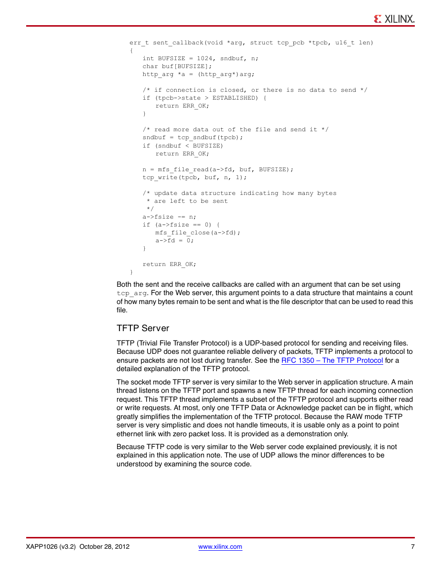
send buffers for more data. The sent_callback is structured as follows:
XAPP1026 (v3.2) October 28, 2012
www.xilinx.com
6
�
err_t sent_callback(void *arg, struct tcp_pcb *tpcb, u16_t len)
{
int BUFSIZE = 1024, sndbuf, n;
char buf[BUFSIZE];
http_arg *a = (http_arg*)arg;
/* if connection is closed, or there is no data to send */
if (tpcb->state > ESTABLISHED) {
return ERR_OK;
}
/* read more data out of the file and send it */
sndbuf = tcp_sndbuf(tpcb);
if (sndbuf < BUFSIZE)
return ERR_OK;
n = mfs_file_read(a->fd, buf, BUFSIZE);
tcp_write(tpcb, buf, n, 1);
/* update data structure indicating how many bytes
* are left to be sent
*/
a->fsize -= n;
if (a->fsize == 0) {
mfs_file_close(a->fd);
a->fd = 0;
}
return ERR_OK;
}
Both the sent and the receive callbacks are called with an argument that can be set using
tcp_arg. For the Web server, this argument points to a data structure that maintains a count
of how many bytes remain to be sent and what is the file descriptor that can be used to read this
file.
TFTP Server
TFTP (Trivial File Transfer Protocol) is a UDP-based protocol for sending and receiving files.
Because UDP does not guarantee reliable delivery of packets, TFTP implements a protocol to
ensure packets are not lost during transfer. See the RFC 1350 – The TFTP Protocol for a
detailed explanation of the TFTP protocol.
The socket mode TFTP server is very similar to the Web server in application structure. A main
thread listens on the TFTP port and spawns a new TFTP thread for each incoming connection
request. This TFTP thread implements a subset of the TFTP protocol and supports either read
or write requests. At most, only one TFTP Data or Acknowledge packet can be in flight, which
greatly simplifies the implementation of the TFTP protocol. Because the RAW mode TFTP
server is very simplistic and does not handle timeouts, it is usable only as a point to point
ethernet link with zero packet loss. It is provided as a demonstration only.
Because TFTP code is very similar to the Web server code explained previously, it is not
explained in this application note. The use of UDP allows the minor differences to be
understood by examining the source code.
XAPP1026 (v3.2) October 28, 2012
www.xilinx.com
7
�
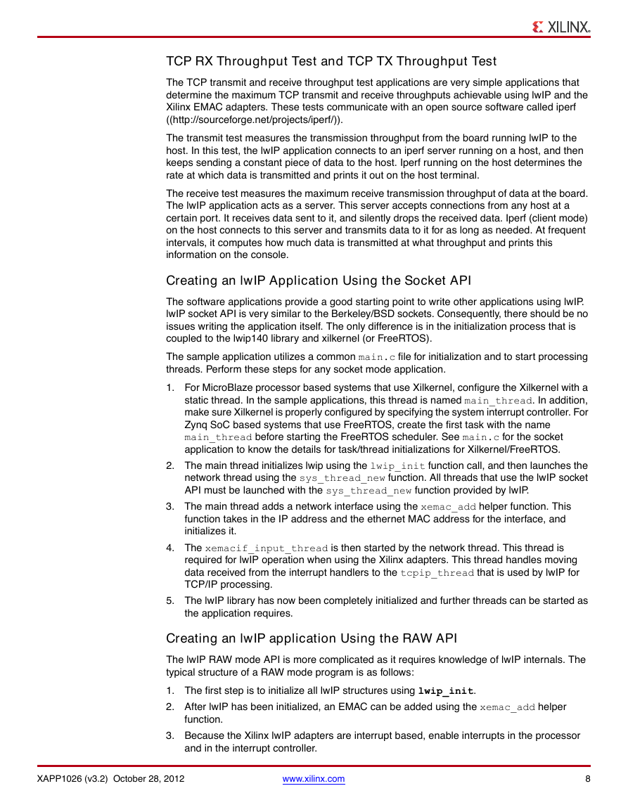
TCP RX Throughput Test and TCP TX Throughput Test
The TCP transmit and receive throughput test applications are very simple applications that
determine the maximum TCP transmit and receive throughputs achievable using lwIP and the
Xilinx EMAC adapters. These tests communicate with an open source software called iperf
((http://sourceforge.net/projects/iperf/)).
The transmit test measures the transmission throughput from the board running lwIP to the
host. In this test, the lwIP application connects to an iperf server running on a host, and then
keeps sending a constant piece of data to the host. Iperf running on the host determines the
rate at which data is transmitted and prints it out on the host terminal.
The receive test measures the maximum receive transmission throughput of data at the board.
The lwIP application acts as a server. This server accepts connections from any host at a
certain port. It receives data sent to it, and silently drops the received data. Iperf (client mode)
on the host connects to this server and transmits data to it for as long as needed. At frequent
intervals, it computes how much data is transmitted at what throughput and prints this
information on the console.
Creating an lwIP Application Using the Socket API
The software applications provide a good starting point to write other applications using lwIP.
lwIP socket API is very similar to the Berkeley/BSD sockets. Consequently, there should be no
issues writing the application itself. The only difference is in the initialization process that is
coupled to the lwip140 library and xilkernel (or FreeRTOS).
The sample application utilizes a common main.c file for initialization and to start processing
threads. Perform these steps for any socket mode application.
1. For MicroBlaze processor based systems that use Xilkernel, configure the Xilkernel with a
static thread. In the sample applications, this thread is named main_thread. In addition,
make sure Xilkernel is properly configured by specifying the system interrupt controller. For
Zynq SoC based systems that use FreeRTOS, create the first task with the name
main_thread before starting the FreeRTOS scheduler. See main.c for the socket
application to know the details for task/thread initializations for Xilkernel/FreeRTOS.
2. The main thread initializes lwip using the lwip_init function call, and then launches the
network thread using the sys_thread_new function. All threads that use the lwIP socket
API must be launched with the sys_thread_new function provided by lwIP.
3. The main thread adds a network interface using the xemac_add helper function. This
function takes in the IP address and the ethernet MAC address for the interface, and
initializes it.
4. The xemacif_input_thread is then started by the network thread. This thread is
required for lwIP operation when using the Xilinx adapters. This thread handles moving
data received from the interrupt handlers to the tcpip_thread that is used by lwIP for
TCP/IP processing.
5. The lwIP library has now been completely initialized and further threads can be started as
the application requires.
Creating an lwIP application Using the RAW API
The lwIP RAW mode API is more complicated as it requires knowledge of lwIP internals. The
typical structure of a RAW mode program is as follows:
1. The first step is to initialize all lwIP structures using lwip_init.
2. After lwIP has been initialized, an EMAC can be added using the xemac_add helper
function.
3. Because the Xilinx lwIP adapters are interrupt based, enable interrupts in the processor
and in the interrupt controller.
XAPP1026 (v3.2) October 28, 2012
www.xilinx.com
8
�



 2023年江西萍乡中考道德与法治真题及答案.doc
 2012年重庆南川中考生物真题及答案.doc
 2013年江西师范大学地理学综合及文艺理论基础考研真题.doc
 2020年四川甘孜小升初语文真题及答案I卷.doc
 2020年注册岩土工程师专业基础考试真题及答案.doc
 2023-2024学年福建省厦门市九年级上学期数学月考试题及答案.doc
 2021-2022学年辽宁省沈阳市大东区九年级上学期语文期末试题及答案.doc
 2022-2023学年北京东城区初三第一学期物理期末试卷及答案.doc
 2018上半年江西教师资格初中地理学科知识与教学能力真题及答案.doc
 2012年河北国家公务员申论考试真题及答案-省级.doc
 2020-2021学年江苏省扬州市江都区邵樊片九年级上学期数学第一次质量检测试题及答案.doc
 2022下半年黑龙江教师资格证中学综合素质真题及答案.doc