logo资料库

dxc-30 维护手册.pdf

第1页 / 共90页
第2页 / 共90页
第3页 / 共90页
第4页 / 共90页
第5页 / 共90页
第6页 / 共90页
第7页 / 共90页
第8页 / 共90页
资料共90页,剩余部分请下载后查看
DXC-D30WS/P
MANUAL STRUCTURE
TABLE OF CONTENTS
SECTION 1 OPERATING INSTRUCTIONS This section
SECTION 2. SERVICE INFORMATION
2-1. BOARD LAYOUT
2-2. REMOVAL OF CABINET
2-2-1. Removal of Side Plate
2-2-2. Cautions on Disassembly/Assembly of Top Chassis
2-3. REPLACEMENT OF MAIN PARTS
2-3-1. Replacement of CCD Unit
2-4. CONNECTORS AND CABLES
2-4-1. Connector Input/Output Signals
2-4-2. Connection Connector
2-5. HOW TO HANDLE OF AT-125 BOARD
2-5-1. How to Attach of the Extension Board EX-591
2-5-2. Replacement Way of ROM(IC102)
2-6. DC-DC CONVERTER VOLTAGE
2-7. SERVICE MODE OPERATION
SECTION 3. ALIGNMENT
3-1. PREPARATION
3-1-1. Equipment Required
3-1-2. Connection
3-1-3. Switch Setting Before Adjustment
3-1-4. Notes on Adjustment
3-1-5. Adjustment Item
3-2. BEFORE ADJUSTMENT
3-2-1. Color Bar Signal Confirmation
3-2-2. Sensitivity Measurement Confirmation
3-3. CAMERA ADJUSTMENT
3-3-1. Sub-Carrier Frequency Adjustment
3-3-2. INT SC-H Phase Adjustment
3-3-3. Y/R-Y/B-Y CLP Level Adjustment
3-3-4. Y/SYNC/R-Y/B-Y Level Adjustment
3-3-5. Carrier Balance Adjustment
3-3-6. Chroma (VBS) Level Adjustment
3-3-7. Y (VBS) Level Adjustment
3-3-8. Y (YC) Level Adjustment
3-3-9. Chroma (YC) Level Adjustment
3-3-10. VF SYNC/BLKG Level Adjustment
3-3-11. CCD Output Level Adjustment
3-3-12. Pedestal Adjustment
3-3-13. Shading Adjustment
3-3-14. Flare Adjustment
3-3-15. MIC LEVEL/MIC Level IND Adjustment
3-3-16. Character Position Adjustment
3-3-17. 4:3 Title Adjustment
9-977-326-11
DIGITAL VIDEO CAMERA DXC-D30WS DXC-D30WSP SERVICE MANUAL Vol. 1 (1st Edition) Power HAD WS
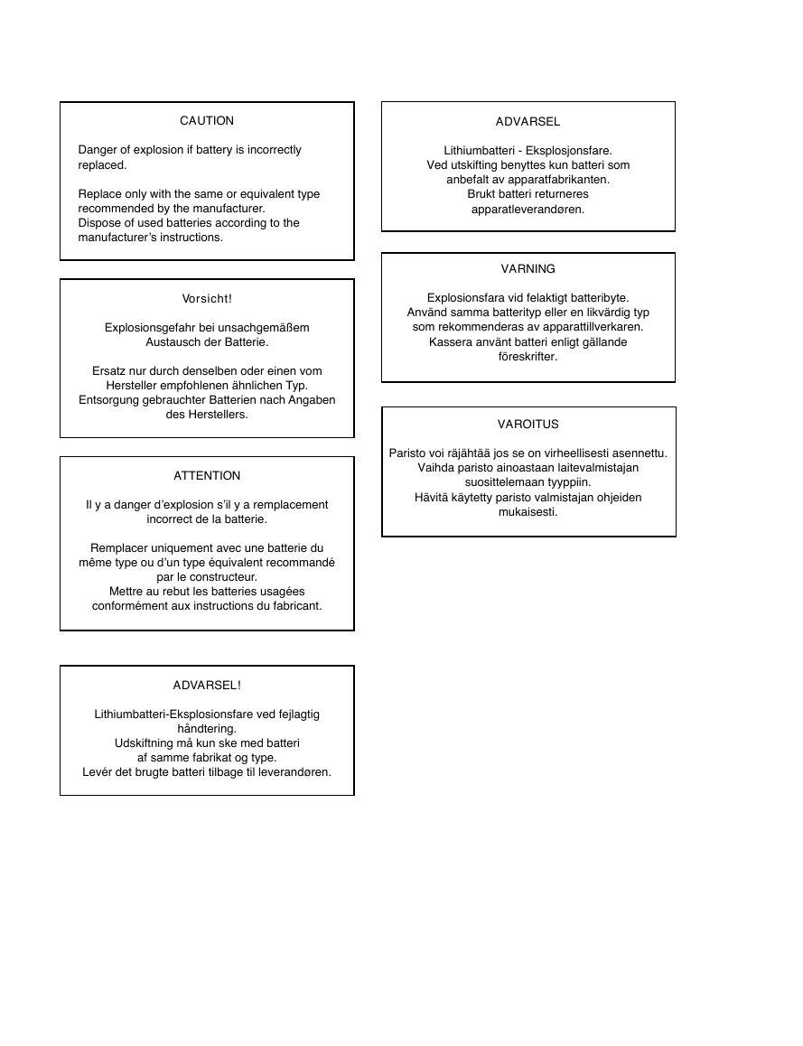
CAUTION ADVARSEL Lithiumbatteri - Eksplosjonsfare. Ved utskifting benyttes kun batteri som anbefalt av apparatfabrikanten. Brukt batteri returneres apparatleverandøren. VARNING Explosionsfara vid felaktigt batteribyte. Använd samma batterityp eller en likvärdig typ som rekommenderas av apparattillverkaren. Kassera använt batteri enligt gällande föreskrifter. VAROITUS Paristo voi räjähtää jos se on virheellisesti asennettu. Vaihda paristo ainoastaan laitevalmistajan suosittelemaan tyyppiin. Hävitä käytetty paristo valmistajan ohjeiden mukaisesti. Danger of explosion if battery is incorrectly replaced. Replace only with the same or equivalent type recommended by the manufacturer. Dispose of used batteries according to the manufacturer’s instructions. Vorsicht! Explosionsgefahr bei unsachgemäßem Austausch der Batterie. Ersatz nur durch denselben oder einen vom Hersteller empfohlenen ähnlichen Typ. Entsorgung gebrauchter Batterien nach Angaben des Herstellers. ATTENTION Il y a danger d’explosion s’il y a remplacement incorrect de la batterie. Remplacer uniquement avec une batterie du même type ou d’un type équivalent recommandé par le constructeur. Mettre au rebut les batteries usagées conformément aux instructions du fabricant. ADVARSEL! Lithiumbatteri-Eksplosionsfare ved fejlagtig håndtering. Udskiftning må kun ske med batteri af samme fabrikat og type. Levér det brugte batteri tilbage til leverandøren.
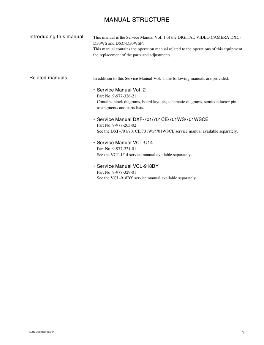
MANUAL STRUCTURE Introducing this manual This manual is the Service Manual Vol. 1 of the DIGITAL VIDEO CAMERA DXC- D30WS and DXC-D30WSP. This manual contains the operation manual related to the operations of this equipment, the replacement of the parts and adjustments. Related manuals In addition to this Service Manual Vol. 1, the following manuals are provided. • Service Manual Vol. 2 Part No. 9-977-326-21 Contains block diagrams, board layouts, schematic diagrams, semiconductor pin assingments and parts lists. • Service Manual DXF-701/701CE/701WS/701WSCE Part No. 9-977-265-02 See the DXF-701/701CE/701WS/701WSCE service manual available separately. • Service Manual VCT-U14 Part No. 9-977-221-01 See the VCT-U14 service manual available separately. • Service Manual VCL-918BY Part No. 9-977-329-01 See the VCL-918BY service manual available separately. DXC-D30WS/P(E)/V1 1
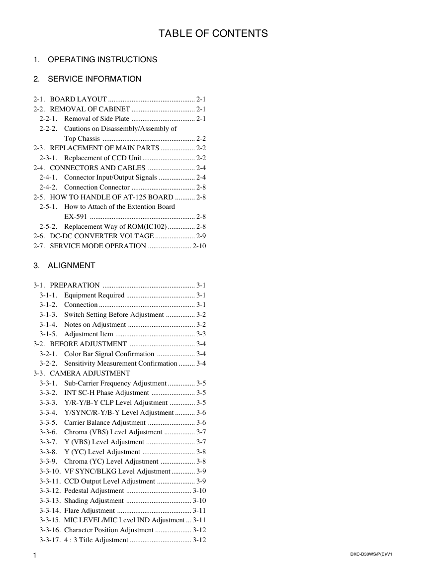
TABLE OF CONTENTS 1. OPERATING INSTRUCTIONS 2. SERVICE INFORMATION 2-1. BOARD LAYOUT ................................................ 2-1 2-2. REMOVAL OF CABINET ................................... 2-1 2-2-1. Removal of Side Plate ................................... 2-1 2-2-2. Cautions on Disassembly/Assembly of Top Chassis ................................................... 2-2 2-3. REPLACEMENT OF MAIN PARTS ................... 2-2 2-3-1. Replacement of CCD Unit............................. 2-2 2-4. CONNECTORS AND CABLES .......................... 2-4 2-4-1. Connector Input/Output Signals .................... 2-4 2-4-2. Connection Connector ................................... 2-8 2-5. HOW TO HANDLE OF AT-125 BOARD ........... 2-8 2-5-1. How to Attach of the Extention Board EX-591 .......................................................... 2-8 2-5-2. Replacement Way of ROM(IC102)............... 2-8 2-6. DC-DC CONVERTER VOLTAGE ...................... 2-9 2-7. SERVICE MODE OPERATION ........................ 2-10 3. ALIGNMENT 3-1. PREPARATION ................................................... 3-1 3-1-1. Equipment Required ...................................... 3-1 3-1-2. Connection ..................................................... 3-1 3-1-3. Switch Setting Before Adjustment ................ 3-2 3-1-4. Notes on Adjustment ..................................... 3-2 3-1-5. Adjustment Item ............................................ 3-3 3-2. BEFORE ADJUSTMENT .................................... 3-4 3-2-1. Color Bar Signal Confirmation ..................... 3-4 3-2-2. Sensitivity Measurement Confirmation ......... 3-4 3-3. CAMERA ADJUSTMENT 3-3-1. Sub-Carrier Frequency Adjustment ............... 3-5 3-3-2. INT SC-H Phase Adjustment ........................ 3-5 3-3-3. Y/R-Y/B-Y CLP Level Adjustment .............. 3-5 3-3-4. Y/SYNC/R-Y/B-Y Level Adjustment ........... 3-6 3-3-5. Carrier Balance Adjustment .......................... 3-6 3-3-6. Chroma (VBS) Level Adjustment ................. 3-7 3-3-7. Y (VBS) Level Adjustment ........................... 3-7 3-3-8. Y (YC) Level Adjustment ............................. 3-8 3-3-9. Chroma (YC) Level Adjustment ................... 3-8 3-3-10. VF SYNC/BLKG Level Adjustment ............. 3-9 3-3-11. CCD Output Level Adjustment ..................... 3-9 3-3-12. Pedestal Adjustment .................................... 3-10 3-3-13. Shading Adjustment .................................... 3-10 3-3-14. Flare Adjustment ......................................... 3-11 3-3-15. MIC LEVEL/MIC Level IND Adjustment ... 3-11 3-3-16. Character Position Adjustment .................... 3-12 3-3-17. 4 : 3 Title Adjustment .................................. 3-12 2 1 DXC-D30WS/P(E)/V1
SECTION 1 OPERATING INSTRUCTIONS This section is extracted from operation manual. 1-1. DXC-D30WS/D30WSP ) 1 ( 1 0 - 9 5 6 - 1 6 8 - 3 o e d i V l a t i g i D a r e m a C 2 1 e g a P s n o i t c u r t s n i g n i t a r e p O S W / L P S W 0 3 D L S W 0 3 D C X D - n o i t a r o p r o C y n o S y b 7 9 9 1 DXC-D30WS/P(E)/V1 1-1 ª
1 - 2 For the customers in the USA This equipment has been tested and found to comply with the limits for a Class A digital device, pursuant to Part 15 of the FCC Rules. These limits are designed to provide reasonable protection against harmful interference when the equipment is operated in a commercial environment. This equipment generates, uses, and can radiate radio frequency energy and, if not installed and used in accordance with the instruction manual, may cause harmful interference to radio communications. Operation of this equipment in a residential area is likely to cause harmful interference in which case the user will be required to correct the interference at his own expense. You are cautioned that any changes or modifications not expressly approved in this manual could void your authority to operate this equipment. The shielded interface cable recommended in this manual must be used with this equipment in order to comply with the limits for a digital device pursuant to Subpart B of Part 15 of FCC Rules. Table of Contents Overview .......................................................................... 14 About This Manual ............................................................ 14 Features ............................................................................. 14 Advanced Menu Settings................................................ 15 Video Output and Viewfinder Picture................................ 16 Battery Pack Operating Times ....................................... 17 Specifications .................................................................. 18 Related Products ................................................................ 19 Measuring Horizontal Resolution ..................................... 21 Chart of Optional Components and Accessories ........ 22 - D X C D 3 0 W S P E / ( ) / V 1 13
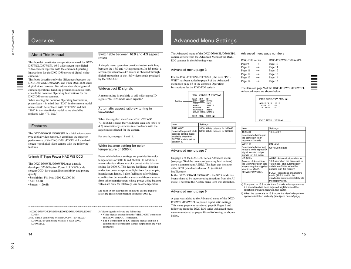
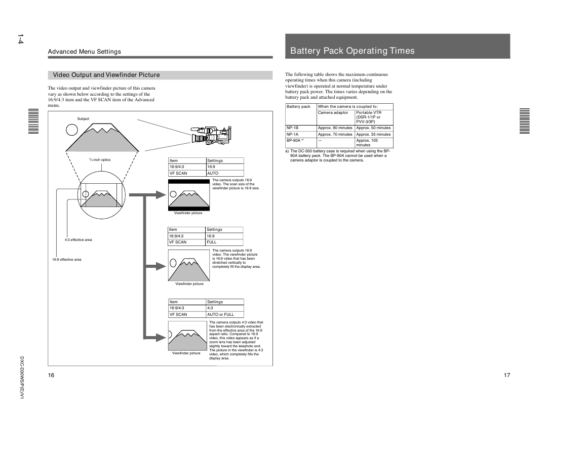
- D X C D 3 0 W S P E / ( Overview Advanced Menu Settings The Advanced menu of the DXC-D30WSL/D30WSPL camera differs from the Advanced Menu of the DXC- D30 cameras in the following ways. Advanced menu page 3 For the DXC-D30WSL/D30WSPL, the item “PRE. WHT” has been added to page 3 of the Advanced menu (see page 58 of the common Operating Instructions for the DXC-D30 series). Advanced menu page numbers DXC-D30 series n Page 9 Page 10 n Page 11 n Page 12 n Page 13 n Page 14 n DXC-D30WSL/D30WSPL Page 10 Page 11 Page 12 Page 13 Page 14 Page 15 The items on page 9 of the DXC-D30WSL/D30WSPL Advanced menu are shown below. P A G E 9 ( N E X Tm$ P R E Vm4) m1 6 : 9 / 4 : 3 : 1 6 : 9 W I D E I D : O N V F S C A N : A U T O E X I T M E N U ( Y E Sm4) Item 16:9/4:3 Selects whether to put the camera in 16:9 mode or 4:3 mode. WIDE ID Selects whether or not to add a wide aspect ID signal to video output signals in 16:9 mode. VF SCAN Selects 16:9 or 4:3 as the viewfinder scan size when using the supplied viewfinder (DXF- 701WS/701WSCE). Settings 16:9, 4:3 a) ON: Add OFF: Do not add AUTO: Automatically switch to 16:9 size when the camera is in 16:9 mode, and automatically switch to 4:3 size when the camera is in 4:3 mode.a) FULL: Regardless of camera’s mode (16:9 b) or 4:3), the viewfinder picture completely fills the display area. a) Compared to 16:9 mode, the 4:3 mode video appears as if a zoom lens has been adjusted slightly toward the telephoto end (see figure on next page). b) When the camera is in 16:9 mode, the viewfinder picture appears stretched vertically (see figure on next page). 15 ) / V 1 About This Manual This booklet constitutes an operation manual for DXC- D30WSL/D30WSPL 16:9 wide-screen type digital video camera together with the common Operating Instructions for the DXC-D30 series of digital video cameras.1) This book describes only the differences between the DXC-D30WSL/D30WSPL and other DXC-D30 series digital video cameras. For information about general camera operations, handling precautions and so forth, consult the common Operating Instructions for the DXC-D30 series cameras. When reading the common Operating Instructions, please keep it in mind that “D30” in the camera model name should be replaced with “D30WS” and that “701” in the viewfinder model name should be replaced with “701WS.” Features Switchable between 16:9 and 4:3 aspect ratios A simple menu operation provides instant switching between the 16:9 and 4:3 aspect ratios. In 4:3 mode, a screen equivalent to a 4:3 screen is obtained through digital processing of the 16:9 video signals produced by the WS CCD. Wide-aspect ID signals A menu setting is available to add wide-aspect ID signals 2) to 16:9-mode video signals.3) Automatic aspect ratio switching in viewfinder When the supplied viewfinder (DXF-701WS/ 701WSCE) is used, the viewfinder scan size (16:9 or 4:3) automatically switches in accordance with the aspect ratio selected for the camera. The DXC-D30WSL/D30WSPL is a 16:9 wide-screen type digital video camera. It combines the superior performance of the DXC-D30L/D30PL 4:3 standard- screen type digital video camera with the following features. For details, see pages 15 and 16. White balance setting for color temperature of 3000 K 2/3-inch IT Type Power HAD WS CCD The DXC-D30WSL/D30WSPL uses a newly developed 520,000-pixel Power HAD WS (wide screen) CCD, for outstanding sensitivity and picture quality. • Sensitivity: F11.0 (at 3200 K, 2000 lx) • S/N: 63 dB • Smear: –120 dB Preset white balance settings are provided for color temperatures of 3200 K and 5600 K. In addition, a menu selection allows use of a preset white balance setting for 3000 K. This feature facilitates shooting under low color temperature light from for example, incandescent lamps. It also facilitates color balance coordination between this camera and those cameras from other manufacturers whose preset white balance values are only for relatively low color temperature. Addition P A G E 3 ( N E X Tm$ P R E Vm4) mA W B M E M : 2 P R E . W H T : 3 2 0 0 T O N E : O F F B A R S : S M P T E R E M O T E 1 : R E C R E M O T E 2 : M A R K B A U D R A T E : 3 8 4 0 0 E X I T M E N U ( Y E Sm4) Settings 3200: White balance for 3200 K 3000: White balance for 3000 K Item PRE. WHT Selects the preset white balance setting made available when the FILTER knob is set to position 1. Advanced menu page 7 On page 7 of the DXC-D30 series Advanced menu (see page 60 of the common Operating Instructions) there is a menu item A.IRIS. This item can be set to either STD (standard value) or AI (artificial intelligence). In the DXC-D30WSL/D30WSPL, the STD mode has been enhanced by incorporating functions from the AI mode. Therefore the A.IRIS menu item was abolished. See page 15 for instructions on how to use the menu to select the preset white balance setting for 3000 K. Advanced menu page 9 .......................................................................................................................................................................................................... 1) DXC-D30F/D30PF/D30K/D30PK/D30L/D30PL/D30H/ D30PH 2) ID signals complying with EIAJ CPR-1204 (DXC- D30WSL) or complying with ETS WSS (DXC- D30WSPL). 3) Video signals refers to the following: • Video signals output from the VIDEO OUT connector and MONITOR OUT connector. • The Y component of Y/C separate signals and the Y component of component signals output from the VTR connector. A page was added to the Advanced menu of the DXC- D30WSL/D30WSPL to permit aspect ratio settings. This menu page was numbered page 9. Pages 9 and following from the DXC-D30 series Advanced menu were renumbered as pages 10 and following, as shown below. 14 1 - 3
1 - 4 Advanced Menu Settings Video Output and Viewfinder Picture The video output and viewfinder picture of this camera vary as shown below according to the settings of the 16:9/4:3 item and the VF SCAN item of the Advanced menu. Subject 2/3-inch optics 4:3 effective area 16:9 effective area Battery Pack Operating Times The following table shows the maximum continuous operating times when this camera (including viewfinder) is operated at normal temperature under battery pack power. The times varies depending on the battery pack and attached equipment. Battery pack When the camera is coupled to: Camera adaptor Portable VTR (DSR-1/1P or PVV-3/3P) Approx. 90 minutes Approx. 50 minutes Approx. 70 minutes Approx. 35 minutes — Approx. 105 minutes NP-1B NP-1A BP-90A a) a) The DC-500 battery case is required when using the BP- 90A battery pack. The BP-90A cannot be used when a camera adaptor is coupled to the camera. Item 16:9/4:3 VF SCAN Settings 16:9 AUTO The camera outputs 16:9 video. The scan size of the viewfinder picture is 16:9 size. Viewfinder picture Item 16:9/4:3 VF SCAN Settings 16:9 FULL The camera outputs 16:9 video. The viewfinder picture is 16:9 video that has been stretched vertically to completely fill the display area. Viewfinder picture Item 16:9/4:3 VF SCAN Settings 4:3 AUTO or FULL The camera outputs 4:3 video that has been electronically extracted from the effective area of the 16:9 aspect ratio. Compared to 16:9 video, this video appears as if a zoom lens has been adjusted slightly toward the telephoto end. The picture in the viewfinder is 4:3 video, which completely fills the display area. Viewfinder picture - D X C D 3 0 W S P E / ( ) / V 1 16 17
分享到:
收藏