logo资料库

东芝nand flash资料.pdf

第1页 / 共90页
第2页 / 共90页
第3页 / 共90页
第4页 / 共90页
第5页 / 共90页
第6页 / 共90页
第7页 / 共90页
第8页 / 共90页
资料共90页,剩余部分请下载后查看
1. INTRODUCTION
1.1. General Description
1.2. Definitions and Abbreviations
1.3. Features
1.4. Diagram Legend
2. PHYSICAL INTERFACE
2.1. Pin Descriptions
2.2. PIN ASSIGNMENT (TOP VIEW)
SDR
only
SDR
only
Vss NC NU or VssQ NU or VccQ DQ7 DQ6 DQ5 DQ4 NU or VssQ NU or VccQ VccQ VCC VSS NU VccQ NU or VssQ DQ3 DQ2 DQ1 DQ0 NU or VccQ NU or VssQ NC Vss
Vcc Vss NC NC NC 1
0
0
1 NC VCC VSS NC NC CLE ALE
NC NC NC Vss Vcc
Tx58TEGxDCJ
SDR/Toggle
DDR1.0
SDR/Toggle
DDR1.0
Vcc Vss NC NC NC 1
0
0
1 NC VCC VSS NC NC CLE ALE
NC NC NC Vss Vcc
1 48 2 47 3 46 4 45 5 44 6 43 7 42 8 41 9 40 10 39 11 38 12 37 13 36 14 35 15 34 16 33 17 32 18 31 19 30 20 29 21 28 22 27 23 26 24 25
Vss NC VssQ VccQ DQ7 DQ6 DQ5 DQ4 VssQ VccQ VccQ VCC VSS DQS VccQ VssQ DQ3 DQ2 DQ1 DQ0 VccQ VssQ NC Vss
2.3. BLOCK DIAGRAM
Address register
to
Row address buffer decoder
ALE
CLE
DQ7
VSS
DQ0
VCC
Logic control
HV generator
Control circuit
Memory cell array
Sense amp
Data register
Column decoder
Column buffer
Command register
DQS
Status register
I/O Control circuit
VCC
Row address buffer decoder
VSS
Logic control
HV generator
Control circuit
Memory cell array
Sense amp
Data register
Column decoder
Column buffer
Command register
Status register
I/O Control circuit
1
1
Address register
Row address buffer decoder
VSS
VCC
Logic control
HV generator
Control circuit
Memory cell array
Sense amp
Data register
Column decoder
Column buffer
Command register
Status register
I/O Control circuit
to
0
ALE
CLE
0
DQ7
DQ0
VSS
VCC
VCC
VSS
Row address buffer decoder
Logic control
HV generator
Control circuit
Memory cell array
Sense amp
Data register
Column decoder
Column buffer
Command register
Status register
I/O Control circuit
1
1
Address register
Row address buffer decoder
Logic control
HV generator
Control circuit
Memory cell array
Sense amp
Data register
Column decoder
Column buffer
Command register
Status register
I/O Control circuit
to
0
ALE
CLE
0
DQ7
DQ0
2.4. Independent Data Buses
2.5. Absolute Maximum DC Rating
2.6. Operating Temperature Condition
2.7. Recommended Operating Conditions
2.8. Valid Blocks
NOTE:
1) The device occasionally contains unusable blocks.
2) The first block (Block 0) is guaranteed to be a valid block at the time of shipment.
3) The specification for the minimum number of valid blocks is applicable over the device lifetime.
4) The number of valid blocks includes extended blocks.
2.9. AC Overshoot/Undershoot Requirements
2.10. DC Operating Characteristics
1)*1: Icco0 is the average current during R/B signal=”Busy” state.
2)*2: All operation current are without data cache.
2.11. Input/Output Capacitance (TOPER =25℃, f=1MHz)
2.12. DQ Driver Strength
2.13. Input/Output Slew rate
2.14. R/ and SR[6] Relationship
2.15. Write Protect
3. MEMORY ORGANIZATION
3.1. Addressing
3.1.1. Plane Addressing
3.1.2. Extended Blocks Arrangement
3.2. Factory Defect Mapping
3.2.1. Device Requirements
3.2.2. Host Requirements
4. FUNCTION DESCRIPTION
4.1. Discovery and Initialization
4.1.1. Single Channel Discovery
4.1.2. Dual Channel Discovery
4.2. Mode Selection
H: VIH, L: VIL, *: VIH or VIL
4.2.1. Toggle DDR1.0 General Timing
4.2.1.1. Command Latch Cycle
4.2.1.2. Address Latch Cycle
4.2.1.3. Basic Data Input Timing
4.2.1.4. Basic Data Output Timing
4.2.1.5. Read ID Operation
4.2.1.6. Status Read Cycle
4.2.1.7. Set Feature
4.2.1.8. Get Feature
4.2.1.9. Page Read Operation
4.2.1.10. Page Program Operation
4.2.2. SDR General Timing
4.2.2.1. Command Latch Cycle
4.2.2.2. Address Latch Cycle
4.2.2.3. Basic Data Input Timing
4.2.2.4. Basic Data Output Timing
4.2.2.5. Read ID Operation
4.2.2.6. Status Read Cycle
4.2.2.7. Set Feature
4.2.2.8. Get Feature
4.2.2.9. Page Read Operation
4.2.2.10. Page Program Operation
4.3. AC Timing Characteristics
4.3.1. Timing Parameters Description
4.3.2. Timing Parameters Table
5. COMMAND DESCRIPTION AND DEVICE OPERATION
5.1. Basic Command Sets
5.2. Basic Operation
5.2.1. Page Read Operation
5.2.1.1. Page Read Operation with Random Data Output
5.2.1.2. Data Out After Status Read
5.2.2. Sequential Cache Read Operation
5.2.3. Random Cache Read Operation
5.2.4. Page Program Operation
5.2.4.1. Program Operation with Random Data Input
5.2.5. Cache Program Operation
5.2.6. Block Erase Operation
5.2.7. Copy-Back Program Operation
5.2.7.1. Copy-Back Program Operation with Random Data Input
5.2.8. Set Feature Operation
5.2.8.1. Driver strength setting (10h)
5.2.9. Get Feature Operation
5.2.10. Read ID Operation
5.2.10.1. 00h Address ID Definition
5.2.10.2. 40h Address ID Definition
5.2.11. Read Status Operation
5.2.12. Reset Operation
When Reset (FFh) command is input during Program operation
When Reset (FFh) command is input during Erase operation
When Reset (FFh) command is input during Read operation
When Read Status command (70h) is input after Reset operation
When two or more Reset commands are input in succession
5.2.13. Reset LUN Operation
5.3. Extended Operation
5.3.1. Extended Command Sets
5.3.2. Page Copy (2) Operation
5.3.3. Device Identification Table Read Operation
5.3.4. Device Identification Table Definition
5.3.5. Read Status Enhanced
5.3.6. Read LUN #0 Status Operation
5.4. Interleaving Operation
5.4.1. Interleaving Page Program
5.4.2. Interleaving Page Read
5.4.3. Interleaving Block Erase
5.4.4. Interleaving Read to Page Program
5.4.5. Interleaving Copy-Back Program (1/2)
5.4.6. Interleaving Copy-Back Program (2/2)
6. APPLICATION NOTES AND COMMENTS
DQS
DQS
DQS
DQS
R/
R/
DQS
DQS
R/
DQS
R/
DQS
R/
DQS
tWH
tCH
CLE
tCLS
tCLS
tWP
tALH
tDS
tDH
tALS
tDS
tDH
: VIH or VIL
ADD
ADD
tCS
tWP
ALE
CLE
: VIH or VIL
tCLH
tCH
tCH
tCLH
ADD
tWC
tWH
tWP
tDS
tDH
tWC
C
tWH
tWP
tDS
tDH
tDS
tDH
ALE
tCS
tCS
tDS
tDH
ADD
tWP
tWH
tWP
tALH
tALS
ADD
tRHOH
tRHOH
tRR
Command
tREA
tRLOH
tRLOH
tDS
tDH
tREA
tREA
tCLHZ
tRP
tREH
tRP
tRHZ
tRP
tRC
tCHZ
ALE
tALH
tCR
tCS2
tCH
tCLH
tCLS2
CLE
Dout
Dout
tALH
tCS
tCH
tCLS
tCS
tDS
tDH
tDS
tDH
DIN N
CLE
ALE
tCH
tCLH
DIN 1
DIN 0
tDS
tDH
tWC
tALS
tWP
tWH
tWP
tWP
If Fail
tDH
tALH
tCH
tCS
tCLS
tALS
tALH
tCH
tDS
tCS
tCLS
ALE
CLE
: VIH or VIL
*: 70h represents the hexadecimal number
: VIH or VIL
Status output
70h*
tREA
tRHZ
tDH
tDS
tIR
tRHOH
tWHR
tWHC
tCHZ
tCH
tWP
tCEA
tCR
tCS
tCLS
tCLH
CLE
tCLR
If Fail
: Do not input data while data is being output.
: VIH or VIL
tCEA
DOUT N ( 1
DOUT N
00h
tDS
tDH
Data out from Col. Add. N
tREA
tRR
tRC
tALS
tCH
tCLH
tCLS
tCS
tWB
tDS
tDH
tR
tCLR
tALH
tDS
tDH
tDS
tDH
tDS
tDH
tDS
tDH
ALE
CLE
tALH
tALS
tWC
tDS
tDH
tCH
tCLH
tCLS
tCS
ADD
ADD
ADD
ADD
ADD
30h
*) M: up to 17664 (byte input data for (8 device).
tADL
DIN N+1
80h
ADD
ADD
ADD
Status output
70h
10h
DINM
DINN
ADD
tALS
tALH
tDS
tWB
tPROG
tDH
tDS
tDH
tCS
: Do not input data while data is being output.
tALH
tDH
tDS
tCS
tCH
tCLH
: VIH or VIL
ALE
CLE
tDH
tDS
tALS
tCLS
tCLS
ADD
30
tRST for read
00
FF
00
tRST for erase
00
FF
D0
Internal erase voltagtRST (max 30 (s)
e
00
tRST for program
00
FF
10
80
Internal VPP
FF
FF
FF
The second command is invalid, but the third command is valid.
(1)
(2)
(3)
FF
FF
10
70
FF
Status : Pass/Fail ( Pass
: Ready/Busy ( Ready
80
FF
Address input
Command other than “81h”, “85h”, “11h” , “15h” or “FFh”
80
Programming cannot be executed.
10
XX
Mode specified by the command.
VCCQ ( 3.3 V / 1.8V Ta ( 25 C CL ( 50 pF
tf
tr
R
tr
tf
5 ns
10 ns
15 ns
2 K(
3 K(
4 K(
1 K(
0
0.5 (s
1.0 (s
1.5 (s
CL
R
VSS
Device
VCCQ
VCCQ
VOH
Busy
VOL
VOH
tr
VOL
VCCQ
Ready
tf
Fail
80
10
80
10
Address M
Data input
70
I/O
Address N
Data input
If the programming result for page address M is Fail, do not try to program the page to address N in another block without the data input sequence.
Because the previous input data has been lost, the same input sequence of 80h command, address and data is necessary.
10
80
M
N
Read operation
Program operation
CLE
Address input
00h
ALE
DQx
Ignored
30h
CLE
ALE
DQx
Address input
Ignored
80h
Data input
Program
Erase
7. Package Dimensions
8. Revision History
RESTRICTIONS ON PRODUCT USE
Bad Block
Bad Block
Block A
Block B
Error occurs
Buffer memory
TOSHIBA CONFIDENTIAL Tx58TEGxDCJTAx0 TOSHIBA NAND memory Toggle DDR1.0 Technical Data Sheet Rev. 0.3 2012 – 04 – 10 TOSHIBA Semiconductor & Storage Products Memory Division TC58TEG6DCJTA00 / TC58TEG6DCJTAI0 TH58TEG7DCJTA20 / TH58TEG7DCJTAK0 TH58TEG8DCJTA20 / TH58TEG8DCJTAK0 0 TENTATIVE 2012-04-10C
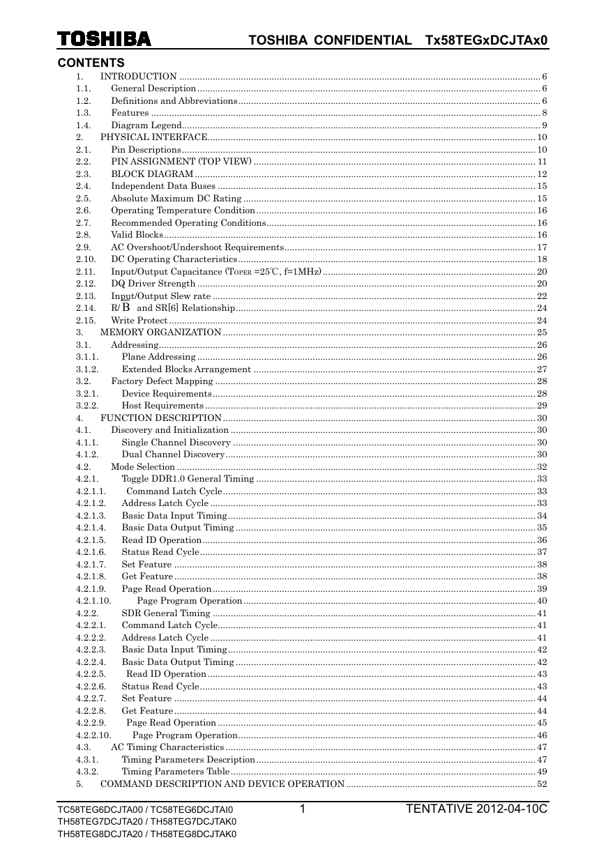
TOSHIBA CONFIDENTIAL Tx58TEGxDCJTAx0 CONTENTS INTRODUCTION ............................................................................................................................................. 6 1. General Description ...................................................................................................................................... 6 1.1. Definitions and Abbreviations ...................................................................................................................... 6 1.2. Features ........................................................................................................................................................ 8 1.3. Diagram Legend ............................................................................................................................................ 9 1.4. PHYSICAL INTERFACE ................................................................................................................................ 10 2. Pin Descriptions .......................................................................................................................................... 10 2.1. PIN ASSIGNMENT (TOP VIEW) .............................................................................................................. 11 2.2. BLOCK DIAGRAM ..................................................................................................................................... 12 2.3. Independent Data Buses ............................................................................................................................ 15 2.4. Absolute Maximum DC Rating .................................................................................................................. 15 2.5. Operating Temperature Condition ............................................................................................................. 16 2.6. Recommended Operating Conditions ......................................................................................................... 16 2.7. Valid Blocks ................................................................................................................................................. 16 2.8. 2.9. AC Overshoot/Undershoot Requirements .................................................................................................. 17 2.10. DC Operating Characteristics .................................................................................................................... 18 2.11. Input/Output Capacitance (TOPER =25℃, f=1MHz) ................................................................................... 20 2.12. DQ Driver Strength .................................................................................................................................... 20 2.13. Input/Output Slew rate .............................................................................................................................. 22 2.14. R/ B and SR[6] Relationship ..................................................................................................................... 24 2.15. Write Protect ............................................................................................................................................... 24 3. MEMORY ORGANIZATION .......................................................................................................................... 25 Addressing ................................................................................................................................................... 26 3.1. Plane Addressing .................................................................................................................................... 26 3.1.1. Extended Blocks Arrangement .............................................................................................................. 27 3.1.2. 3.2. Factory Defect Mapping ............................................................................................................................. 28 Device Requirements .............................................................................................................................. 28 3.2.1. 3.2.2. Host Requirements ................................................................................................................................. 29 FUNCTION DESCRIPTION .......................................................................................................................... 30 4. Discovery and Initialization ....................................................................................................................... 30 4.1. 4.1.1. Single Channel Discovery ...................................................................................................................... 30 4.1.2. Dual Channel Discovery ......................................................................................................................... 30 4.2. Mode Selection ............................................................................................................................................ 32 4.2.1. Toggle DDR1.0 General Timing ............................................................................................................. 33 4.2.1.1. Command Latch Cycle .......................................................................................................................... 33 4.2.1.2. Address Latch Cycle ............................................................................................................................... 33 4.2.1.3. Basic Data Input Timing ........................................................................................................................ 34 4.2.1.4. Basic Data Output Timing ..................................................................................................................... 35 4.2.1.5. Read ID Operation .................................................................................................................................. 36 Status Read Cycle ................................................................................................................................... 37 4.2.1.6. 4.2.1.7. Set Feature ............................................................................................................................................. 38 4.2.1.8. Get Feature ............................................................................................................................................. 38 4.2.1.9. Page Read Operation .............................................................................................................................. 39 Page Program Operation .................................................................................................................. 40 4.2.1.10. 4.2.2. SDR General Timing .............................................................................................................................. 41 4.2.2.1. Command Latch Cycle ............................................................................................................................ 41 4.2.2.2. Address Latch Cycle ............................................................................................................................... 41 4.2.2.3. Basic Data Input Timing ........................................................................................................................ 42 4.2.2.4. Basic Data Output Timing ..................................................................................................................... 42 Read ID Operation ................................................................................................................................ 43 4.2.2.5. 4.2.2.6. Status Read Cycle ................................................................................................................................... 43 4.2.2.7. Set Feature ............................................................................................................................................. 44 4.2.2.8. Get Feature ............................................................................................................................................. 44 Page Read Operation ............................................................................................................................ 45 4.2.2.9. Page Program Operation .................................................................................................................... 46 4.2.2.10. 4.3. AC Timing Characteristics ......................................................................................................................... 47 Timing Parameters Description ............................................................................................................. 47 4.3.1. 4.3.2. Timing Parameters Table ....................................................................................................................... 49 COMMAND DESCRIPTION AND DEVICE OPERATION .......................................................................... 52 5. TC58TEG6DCJTA00 / TC58TEG6DCJTAI0 TH58TEG7DCJTA20 / TH58TEG7DCJTAK0 TH58TEG8DCJTA20 / TH58TEG8DCJTAK0 1 TENTATIVE 2012-04-10C
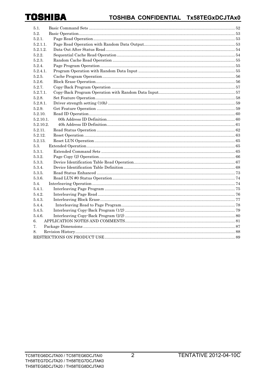
TOSHIBA CONFIDENTIAL Tx58TEGxDCJTAx0 Basic Command Sets .................................................................................................................................. 52 5.1. Basic Operation ........................................................................................................................................... 53 5.2. Page Read Operation .............................................................................................................................. 53 5.2.1. 5.2.1.1. Page Read Operation with Random Data Output ................................................................................. 53 5.2.1.2. Data Out After Status Read ................................................................................................................... 54 Sequential Cache Read Operation ......................................................................................................... 54 5.2.2. 5.2.3. Random Cache Read Operation ............................................................................................................. 55 Page Program Operation ........................................................................................................................ 55 5.2.4. Program Operation with Random Data Input ...................................................................................... 55 5.2.4.1. Cache Program Operation ...................................................................................................................... 56 5.2.5. 5.2.6. Block Erase Operation ............................................................................................................................ 56 5.2.7. Copy-Back Program Operation .............................................................................................................. 57 5.2.7.1. Copy-Back Program Operation with Random Data Input .................................................................... 57 5.2.8. Set Feature Operation ............................................................................................................................ 58 5.2.8.1. Driver strength setting (10h) ................................................................................................................. 59 Get Feature Operation ........................................................................................................................... 59 5.2.9. Read ID Operation .................................................................................................................................. 60 5.2.10. 00h Address ID Definition .................................................................................................................. 60 5.2.10.1. 5.2.10.2. 40h Address ID Definition .................................................................................................................. 61 Read Status Operation ........................................................................................................................... 62 5.2.11. Reset Operation ...................................................................................................................................... 63 5.2.12. Reset LUN Operation ............................................................................................................................. 65 5.2.13. 5.3. Extended Operation .................................................................................................................................... 65 Extended Command Sets ....................................................................................................................... 65 5.3.1. Page Copy (2) Operation ......................................................................................................................... 66 5.3.2. Device Identification Table Read Operation .......................................................................................... 67 5.3.3. 5.3.4. Device Identification Table Definition ................................................................................................... 68 Read Status Enhanced ........................................................................................................................... 73 5.3.5. Read LUN #0 Status Operation ............................................................................................................. 74 5.3.6. Interleaving Operation ............................................................................................................................... 74 5.4. Interleaving Page Program .................................................................................................................... 75 5.4.1. 5.4.2. Interleaving Page Read .......................................................................................................................... 76 Interleaving Block Erase ........................................................................................................................ 77 5.4.3. Interleaving Read to Page Program ..................................................................................................... 78 5.4.4. Interleaving Copy-Back Program (1/2) .................................................................................................. 79 5.4.5. 5.4.6. Interleaving Copy-Back Program (2/2) .................................................................................................. 80 APPLICATION NOTES AND COMMENTS.................................................................................................. 81 6. Package Dimensions ....................................................................................................................................... 87 7. 8. Revision History .............................................................................................................................................. 88 RESTRICTIONS ON PRODUCT USE .................................................................................................................... 89 TC58TEG6DCJTA00 / TC58TEG6DCJTAI0 TH58TEG7DCJTA20 / TH58TEG7DCJTAK0 TH58TEG8DCJTA20 / TH58TEG8DCJTAK0 2 TENTATIVE 2012-04-10C
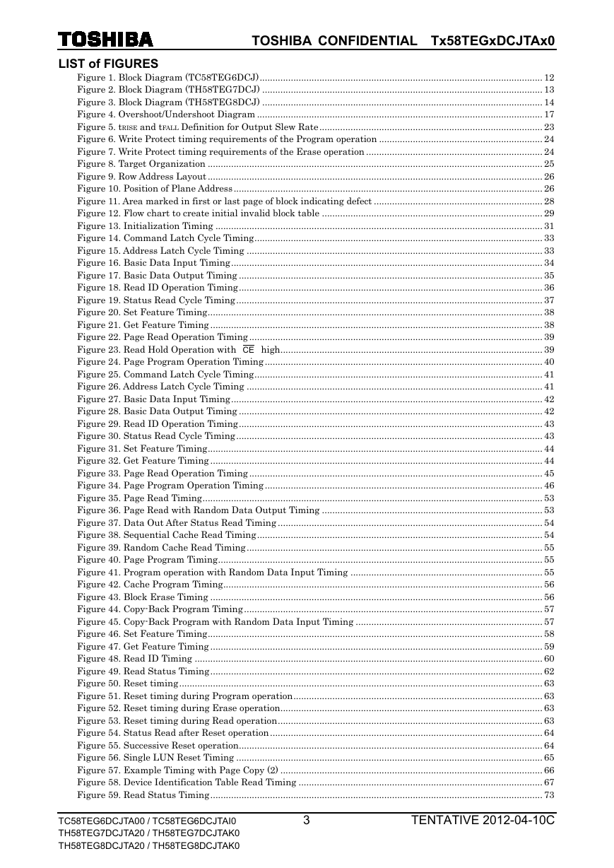
TOSHIBA CONFIDENTIAL Tx58TEGxDCJTAx0 LIST of FIGURES Figure 1. Block Diagram (TC58TEG6DCJ) ............................................................................................................. 12 Figure 2. Block Diagram (TH58TEG7DCJ) ............................................................................................................ 13 Figure 3. Block Diagram (TH58TEG8DCJ) ............................................................................................................ 14 Figure 4. Overshoot/Undershoot Diagram .............................................................................................................. 17 Figure 5. tRISE and tFALL Definition for Output Slew Rate ...................................................................................... 23 Figure 6. Write Protect timing requirements of the Program operation ............................................................... 24 Figure 7. Write Protect timing requirements of the Erase operation .................................................................... 24 Figure 8. Target Organization ................................................................................................................................. 25 Figure 9. Row Address Layout ................................................................................................................................. 26 Figure 10. Position of Plane Address ....................................................................................................................... 26 Figure 11. Area marked in first or last page of block indicating defect ................................................................. 28 Figure 12. Flow chart to create initial invalid block table ..................................................................................... 29 Figure 13. Initialization Timing .............................................................................................................................. 31 Figure 14. Command Latch Cycle Timing ............................................................................................................... 33 Figure 15. Address Latch Cycle Timing .................................................................................................................. 33 Figure 16. Basic Data Input Timing ........................................................................................................................ 34 Figure 17. Basic Data Output Timing ..................................................................................................................... 35 Figure 18. Read ID Operation Timing ..................................................................................................................... 36 Figure 19. Status Read Cycle Timing ...................................................................................................................... 37 Figure 20. Set Feature Timing ................................................................................................................................. 38 Figure 21. Get Feature Timing ................................................................................................................................ 38 Figure 22. Page Read Operation Timing ................................................................................................................. 39 Figure 23. Read Hold Operation with CE high ..................................................................................................... 39 Figure 24. Page Program Operation Timing ........................................................................................................... 40 Figure 25. Command Latch Cycle Timing ............................................................................................................... 41 Figure 26. Address Latch Cycle Timing .................................................................................................................. 41 Figure 27. Basic Data Input Timing ........................................................................................................................ 42 Figure 28. Basic Data Output Timing ..................................................................................................................... 42 Figure 29. Read ID Operation Timing ..................................................................................................................... 43 Figure 30. Status Read Cycle Timing ...................................................................................................................... 43 Figure 31. Set Feature Timing ................................................................................................................................. 44 Figure 32. Get Feature Timing ................................................................................................................................ 44 Figure 33. Page Read Operation Timing ................................................................................................................. 45 Figure 34. Page Program Operation Timing ........................................................................................................... 46 Figure 35. Page Read Timing ................................................................................................................................... 53 Figure 36. Page Read with Random Data Output Timing ..................................................................................... 53 Figure 37. Data Out After Status Read Timing ...................................................................................................... 54 Figure 38. Sequential Cache Read Timing .............................................................................................................. 54 Figure 39. Random Cache Read Timing .................................................................................................................. 55 Figure 40. Page Program Timing ............................................................................................................................. 55 Figure 41. Program operation with Random Data Input Timing .......................................................................... 55 Figure 42. Cache Program Timing ........................................................................................................................... 56 Figure 43. Block Erase Timing ................................................................................................................................ 56 Figure 44. Copy-Back Program Timing ................................................................................................................... 57 Figure 45. Copy-Back Program with Random Data Input Timing ........................................................................ 57 Figure 46. Set Feature Timing ................................................................................................................................. 58 Figure 47. Get Feature Timing ................................................................................................................................ 59 Figure 48. Read ID Timing ...................................................................................................................................... 60 Figure 49. Read Status Timing ................................................................................................................................ 62 Figure 50. Reset timing ............................................................................................................................................ 63 Figure 51. Reset timing during Program operation ................................................................................................ 63 Figure 52. Reset timing during Erase operation ..................................................................................................... 63 Figure 53. Reset timing during Read operation ...................................................................................................... 63 Figure 54. Status Read after Reset operation ......................................................................................................... 64 Figure 55. Successive Reset operation ..................................................................................................................... 64 Figure 56. Single LUN Reset Timing ...................................................................................................................... 65 Figure 57. Example Timing with Page Copy (2) ..................................................................................................... 66 Figure 58. Device Identification Table Read Timing .............................................................................................. 67 Figure 59. Read Status Timing ................................................................................................................................ 73 TC58TEG6DCJTA00 / TC58TEG6DCJTAI0 TH58TEG7DCJTA20 / TH58TEG7DCJTAK0 TH58TEG8DCJTA20 / TH58TEG8DCJTAK0 3 TENTATIVE 2012-04-10C
TOSHIBA CONFIDENTIAL Tx58TEGxDCJTAx0 Figure 60. Read LUN#0 Status Timing ................................................................................................................... 74 Figure 61. Example Timing with Interleaving Page Program ............................................................................... 75 Figure 62. Example Timing with Interleaving Page Read ..................................................................................... 76 Figure 63. Example Timing with Interleaving Block Erase ................................................................................... 77 Figure 64. Example Timing with Interleaving Read to Page Program .................................................................. 78 Figure 65. Example Timing with Interleaving Copy-Back Program ..................................................................... 80 TC58TEG6DCJTA00 / TC58TEG6DCJTAI0 TH58TEG7DCJTA20 / TH58TEG7DCJTAK0 TH58TEG8DCJTA20 / TH58TEG8DCJTAK0 4 TENTATIVE 2012-04-10C
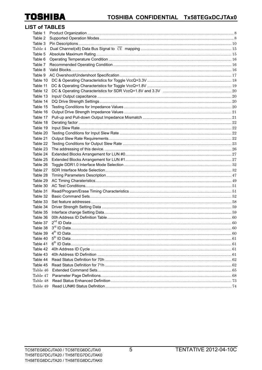
TOSHIBA CONFIDENTIAL Tx58TEGxDCJTAx0 Table 1 Product Organization .................................................................................................................................... 8 Table 2 Supported Operation Modes ......................................................................................................................... 8 Table 3 Pin Descriptions .......................................................................................................................................... 10 Table 4 Dual Channel(x8) Data Bus Signal to CE mapping .................................................................................. 15 Table 5 Absolute Maximum Rating .......................................................................................................................... 15 Table 6 Operating Temperature Condition ............................................................................................................... 16 Table 7 Recommended Operating Condition ........................................................................................................... 16 Table 8 Valid Blocks ................................................................................................................................................. 16 Table 9 AC Overshoot/Undershoot Specification ..................................................................................................... 17 Table 10 DC & Operating Characteristics for Toggle VccQ=3.3V ............................................................................ 18 Table 11 DC & Operating Characteristics for Toggle VccQ=1.8V ............................................................................ 19 Table 12 DC & Operating Characteristics for SDR VccQ=1.8V and 3.3V .............................................................. 20 Table 13 Input/ Output capacitance ......................................................................................................................... 20 Table 14 DQ Drive Strength Settings ....................................................................................................................... 20 Table 15 Testing Conditions for Impedance Values ................................................................................................. 20 Table 16 Output Drive Strength Impedance Values ................................................................................................. 21 Table 17 Pull-up and Pull-down Output Impedance Mismatch ................................................................................ 21 Table 18 Derating factor .......................................................................................................................................... 22 Table 19 Input Slew Rate ......................................................................................................................................... 22 Table 20 Testing Conditions for Input Slew Rate ..................................................................................................... 22 Table 21 Output Slew Rate Requirements ............................................................................................................... 22 Table 22 Testing Conditions for Output Slew Rate .................................................................................................. 23 Table 23 The addressing of this device. .................................................................................................................. 26 Table 24 Extended Blocks Arrangement for LUN #0 ................................................................................................ 27 Table 25 Extended Blocks Arrangement for LUN #1 ................................................................................................ 27 Table 26 Toggle DDR1.0 Interface Mode Selection ................................................................................................. 32 Table 27 SDR Interface Mode Selection .................................................................................................................. 32 Table 28 Timing Parameters Description ................................................................................................................. 47 Table 29 AC Timing Charateristics........................................................................................................................... 49 Table 30 AC Test Conditions.................................................................................................................................... 51 Table 31 Read/Program/Erase Timing Characteristics ............................................................................................ 51 Table 32 Basic Command Sets................................................................................................................................ 52 Table 33 Set feature addresses ............................................................................................................................... 58 Table 34 Driver Strength Setting Data ..................................................................................................................... 59 Table 35 Interface change Setting Data ................................................................................................................... 59 Table 36 00h Address ID Definition Table ................................................................................................................ 60 Table 37 2nd ID Data ................................................................................................................................................ 60 Table 38 3rd ID Data ................................................................................................................................................. 60 Table 39 4th ID Data ................................................................................................................................................. 60 Table 40 5th ID Data ................................................................................................................................................. 61 Table 41 6th ID Data ................................................................................................................................................. 61 Table 42 40h Address ID Cycle ............................................................................................................................... 61 Table 43 40h Address ID Definition ......................................................................................................................... 61 Table 44 Read Status Definition for 70h .................................................................................................................. 62 Table 45 Read Status Definition for 71h .................................................................................................................. 62 Table 46 Extended Command Sets ......................................................................................................................... 65 Table 47 Parameter Page Definitions ...................................................................................................................... 68 Table 48 Read Status Enhanced Definition ............................................................................................................. 73 Table 49 Read LUN#0 Status Definition .................................................................................................................. 74 LIST of TABLES TC58TEG6DCJTA00 / TC58TEG6DCJTAI0 TH58TEG7DCJTA20 / TH58TEG7DCJTAK0 TH58TEG8DCJTA20 / TH58TEG8DCJTAK0 5 TENTATIVE 2012-04-10C
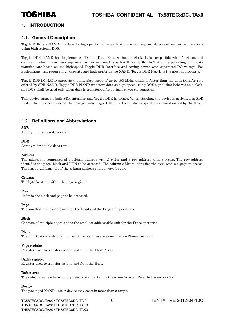
TOSHIBA CONFIDENTIAL Tx58TEGxDCJTAx0 INTRODUCTION 1. 1.1. General Description Toggle DDR is a NAND interface for high performance applications which support data read and write operations using bidirectional DQS. Toggle DDR NAND has implemented ’Double Data Rate’ without a clock. It is compatible with functions and command which have been supported in conventional type NAND(i.e. SDR NAND) while providing high data transfer rate based on the high-speed Toggle DDR Interface and saving power with separated DQ voltage. For applications that require high capacity and high performance NAND, Toggle DDR NAND is the most appropriate. Toggle DDR1.0 NAND supports the interface speed of up to 100 MHz, which is faster than the data transfer rate offered by SDR NAND. Toggle DDR NAND transfers data at high speed using DQS signal that behaves as a clock, and DQS shall be used only when data is transferred for optimal power consumption. This device supports both SDR interface and Toggle DDR interface. When starting, the device is activated in SDR mode. The interface mode can be changed into Toggle DDR interface utilizing specific command issued by the Host. 1.2. Definitions and Abbreviations SDR Acronym for single data rate. DDR Acronym for double data rate. Address The address is comprised of a column address with 2 cycles and a row address with 3 cycles. The row address identifies the page, block and LUN to be accessed. The column address identifies the byte within a page to access. The least significant bit of the column address shall always be zero. Column The byte location within the page register. Row Refer to the block and page to be accessed. Page The smallest addressable unit for the Read and the Program operations. Block Consists of multiple pages and is the smallest addressable unit for the Erase operation. Plane The unit that consists of a number of blocks. There are one or more Planes per LUN. Page register Register used to transfer data to and from the Flash Array. Cache register Register used to transfer data to and from the Host. Defect area The defect area is where factory defects are marked by the manufacturer. Refer to the section 3.2 Device The packaged NAND unit. A device may contain more than a target. TC58TEG6DCJTA00 / TC58TEG6DCJTAI0 TH58TEG7DCJTA20 / TH58TEG7DCJTAK0 TH58TEG8DCJTA20 / TH58TEG8DCJTAK0 6 TENTATIVE 2012-04-10C
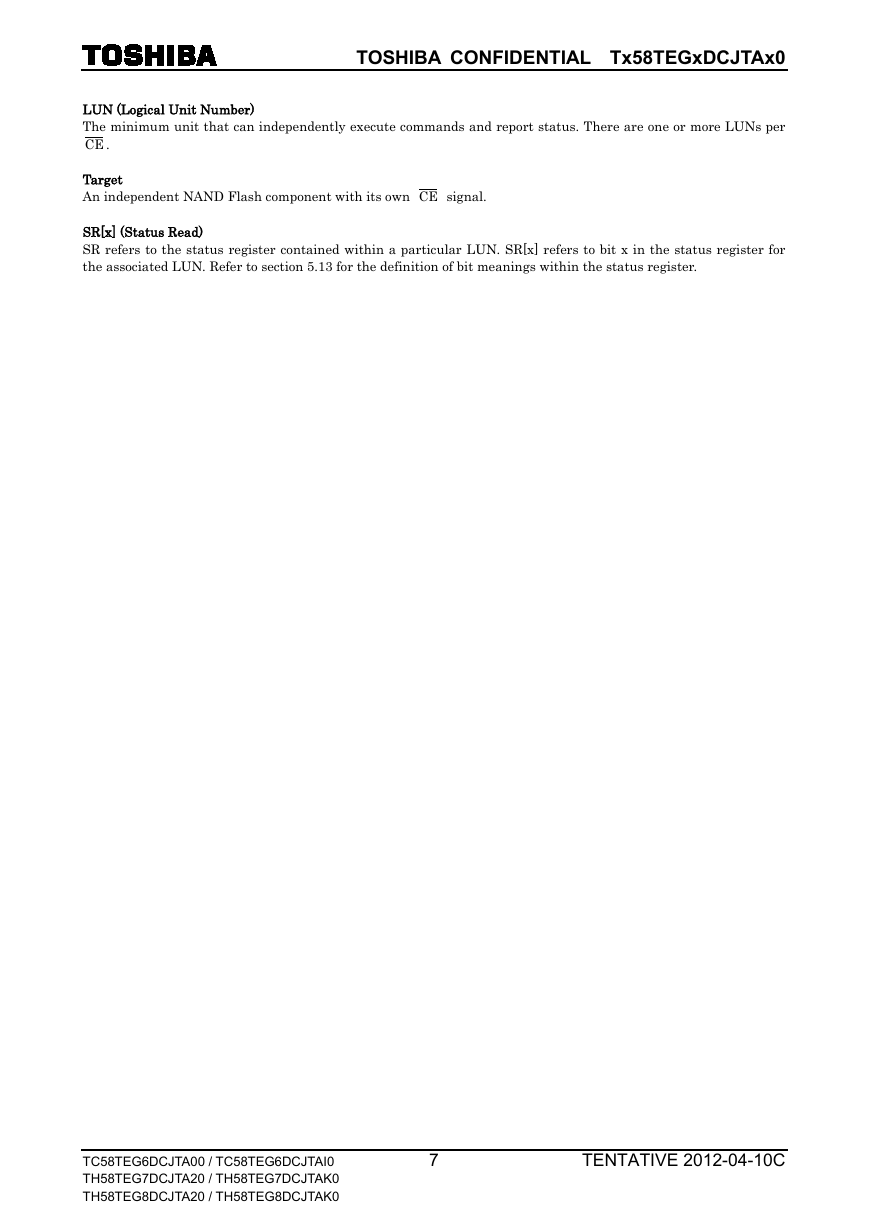
TOSHIBA CONFIDENTIAL Tx58TEGxDCJTAx0 LUN (Logical Unit Number) The minimum unit that can independently execute commands and report status. There are one or more LUNs per CE . Target An independent NAND Flash component with its own CE signal. SR[x] (Status Read) SR refers to the status register contained within a particular LUN. SR[x] refers to bit x in the status register for the associated LUN. Refer to section 5.13 for the definition of bit meanings within the status register. TC58TEG6DCJTA00 / TC58TEG6DCJTAI0 TH58TEG7DCJTA20 / TH58TEG7DCJTAK0 TH58TEG8DCJTA20 / TH58TEG8DCJTAK0 7 TENTATIVE 2012-04-10C
分享到:
收藏