logo资料库

SONY投影机-SRX-R320说明书.pdf

第1页 / 共126页
第2页 / 共126页
第3页 / 共126页
第4页 / 共126页
第5页 / 共126页
第6页 / 共126页
第7页 / 共126页
第8页 / 共126页
资料共126页,剩余部分请下载后查看
Cover
Table of Contents
Manual Structure
Purpose of this manual
Related manuals
Trademarks
1. Installation
Outline
1-1. Removing/Installing the Cabinet Panel
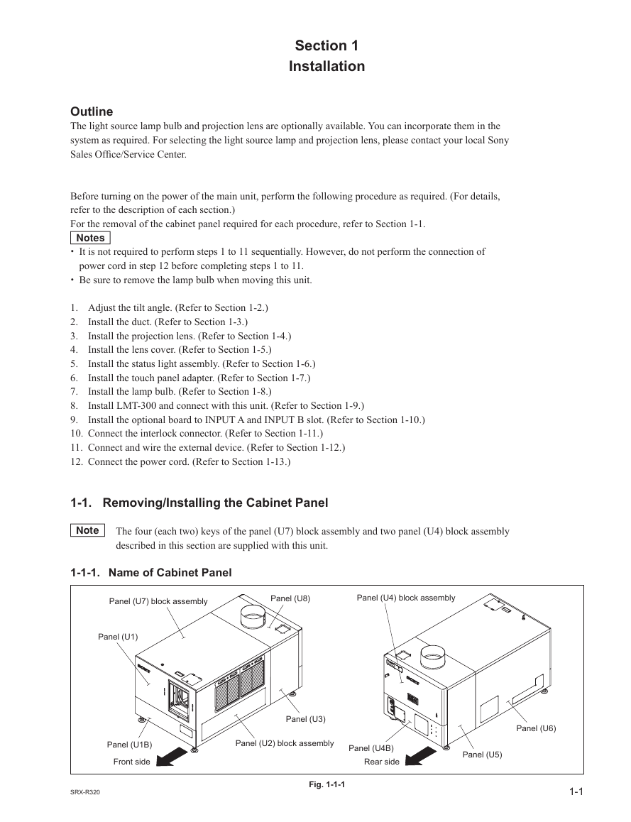
1-1-1. Name of Cabinet Panel
1-1-2. Panel (U7) Block Assembly
1-1-3. Panel (U2) Block Assembly
1-1-4. Panel (U3)
1-1-5. Panel (U6)
1-1-6. Panel (U5)
1-1-7. Panel (U1B)
1-1-8. Panel (U1)
1-1-9. Panel (U4) Block Assembly
1-1-10. Panel (U4B)
1-1-11. Panel (U8)
1-2. Tilt Angle Adjustment
1-3. Installing the Duct
1-4. Installing the Projection Lens
1-5. Installing the Lens Cover
1-6. Installing the Status Light Assembly
1-7. Installing the Touch Panel Adapter
1-8. Installing the Lamp Bulb
1-9. Installing LMT-300 and Connecting with the Unit
1-10. Installing the Optional Board to INPUT A and INPUT B
1-11. Interlock Terminal
1-12. Connecting and Wiring of External Device
1-13. Connecting the Power Cord
1-14. Dimensions
2. Adjustment
2-1. Installation of SRX Controller
2-1-1. Installation
2-1-2. Connection
2-1-3. Startup and Initialization of SRX Controller
2-1-4. Startup of This Unit
2-2. Optical Axis Adjustment of Lamp
2-3. Lens Adjustment (H Shift, V Shift, Zoom, and Focus Adjustments)
2-4. Illumination Area Adjustment and Registration Adjustment
2-4-1. Illumination Area Adjustment
2-4-2. Registration Adjustment
2-5. Screen Illuminance Setting and Color Space Conversion (CSC Adjustment)
2-6. Field Angle Adjustment
2-6-1. Side Masking
2-6-2. Height Masking
2-7. Setting of Function Memory
2-7-1. Setting of New Function Memory
2-7-2. Change in Setting of Registered Function Memory
2-7-3. Copying of Registered Function Memory to Create New Function Memory
2-7-4. Switching of Registered Function Memory
2-8. How to Use the SRX Controller
2-8-1. Configuration
2-8-2. Function Memory
2-8-3. Functions of Each Window
3. Error Message
DIGITAL CINEMA PROJECTOR SRX-R320 INSTALLATION MANUAL 1st Edition
! ! WARNING This manual is intended for qualifi ed service personnel only. To reduce the risk of electric shock, fi re or injury, do not perform any servicing other than that contained in the operating instructions unless you are qualifi ed to do so. Refer all servicing to qualifi ed service personnel. ! WARNUNG Die Anleitung ist nur für qualifi ziertes Fachpersonal bestimmt. Alle Wartungsarbeiten dürfen nur von qualifi ziertem Fachpersonal ausgeführt werden. Um die Gefahr eines elektrischen Schlages, Feuergefahr und Verletzungen zu vermeiden, sind bei Wartungsarbeiten strikt die Angaben in der Anleitung zu befolgen. Andere als die angegeben Wartungsarbeiten dürfen nur von Personen ausgeführt werden, die eine spezielle Befähigung dazu besitzen. ! AVERTISSEMENT Ce manual est destiné uniquement aux personnes compétentes en charge de l’entretien. Afi n de réduire les risques de décharge électrique, d’incendie ou de blessure n’effectuer que les réparations indiquées dans le mode d’emploi à moins d’être qualifi é pour en effectuer d’autres. Pour toute réparation faire appel à une personne compétente uniquement. For kundene i Norge Dette utstyret kan kobles til et IT-strømfordelingssystem. : NETWORK For safety, do not connect the connector for periph- eral device wiring that might have excessive volt- age to the following port. : NETWORK connector Follow the instructions for the above port. SRX-R320
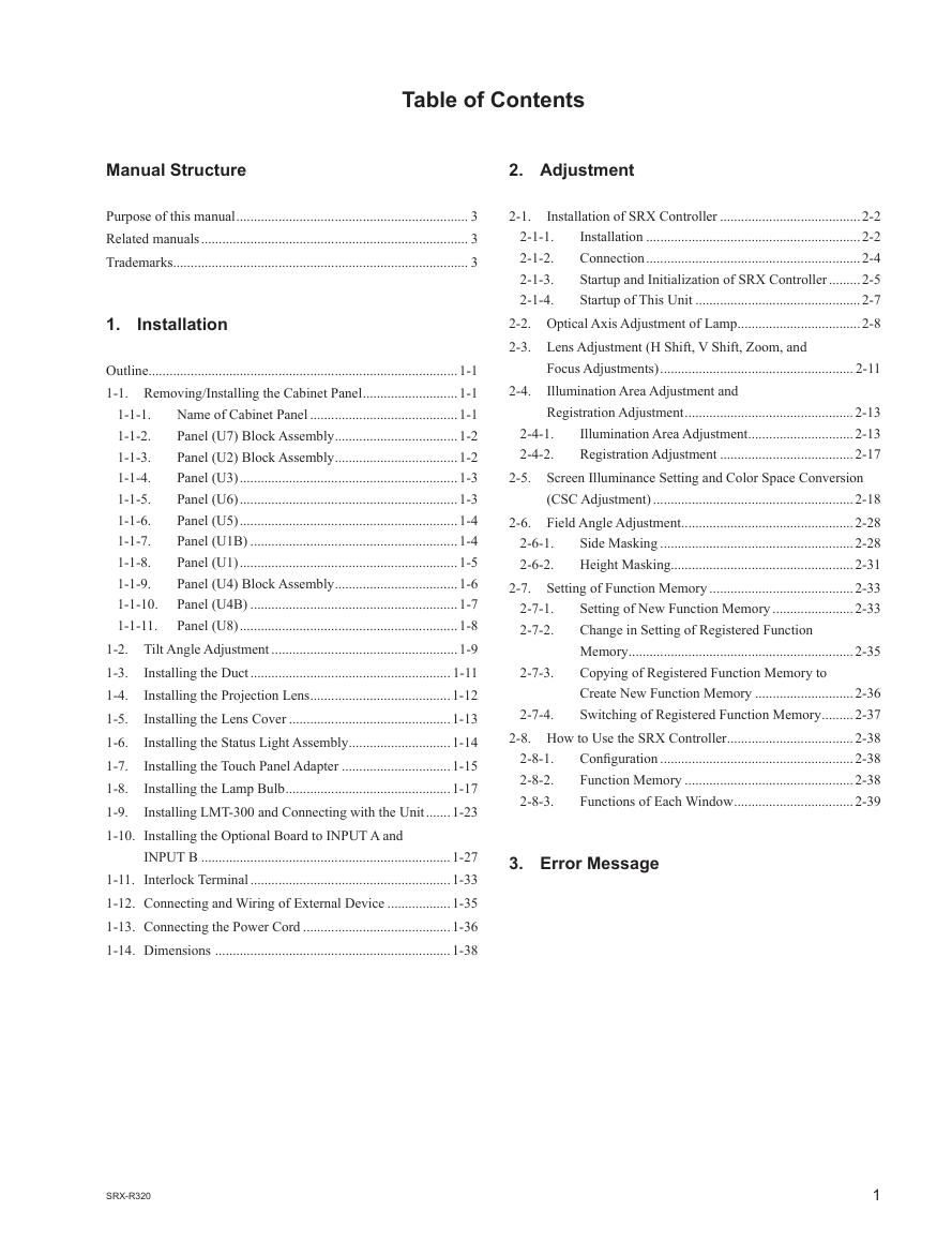
Table of Contents Manual Structure 2. Adjustment Purpose of this manual .................................................................. 3 Related manuals ............................................................................ 3 Trademarks .................................................................................... 3 1. Installation Outline ........................................................................................1-1 1-1. Removing/Installing the Cabinet Panel ...........................1-1 Name of Cabinet Panel ..........................................1-1 1-1-1. Panel (U7) Block Assembly ...................................1-2 1-1-2. Panel (U2) Block Assembly ...................................1-2 1-1-3. Panel (U3) ..............................................................1-3 1-1-4. Panel (U6) ..............................................................1-3 1-1-5. Panel (U5) ..............................................................1-4 1-1-6. Panel (U1B) ...........................................................1-4 1-1-7. Panel (U1) ..............................................................1-5 1-1-8. 1-1-9. Panel (U4) Block Assembly ...................................1-6 1-1-10. Panel (U4B) ...........................................................1-7 Panel (U8) ..............................................................1-8 1-1-11. 1-2. Tilt Angle Adjustment .....................................................1-9 1-3. Installing the Duct ......................................................... 1-11 Installing the Projection Lens ........................................1-12 1-4. Installing the Lens Cover ..............................................1-13 1-5. 1-6. Installing the Status Light Assembly .............................1-14 Installing the Touch Panel Adapter ...............................1-15 1-7. Installing the Lamp Bulb ...............................................1-17 1-8. 1-9. Installing LMT-300 and Connecting with the Unit .......1-23 1-10. Installing the Optional Board to INPUT A and INPUT B .......................................................................1-27 1-11. Interlock Terminal .........................................................1-33 1-12. Connecting and Wiring of External Device ..................1-35 1-13. Connecting the Power Cord ..........................................1-36 1-14. Dimensions ...................................................................1-38 2-1. 2-1-1. 2-1-2. 2-1-3. 2-1-4. Installation of SRX Controller ........................................2-2 Installation .............................................................2-2 Connection .............................................................2-4 Startup and Initialization of SRX Controller .........2-5 Startup of This Unit ...............................................2-7 2-2. Optical Axis Adjustment of Lamp ...................................2-8 2-3. Lens Adjustment (H Shift, V Shift, Zoom, and 2-4. Focus Adjustments) ....................................................... 2-11 Illumination Area Adjustment and Registration Adjustment ................................................2-13 Illumination Area Adjustment ..............................2-13 Registration Adjustment ......................................2-17 2-4-1. 2-4-2. 2-5. Screen Illuminance Setting and Color Space Conversion 2-6-1. 2-6-2. (CSC Adjustment) .........................................................2-18 2-6. Field Angle Adjustment .................................................2-28 Side Masking .......................................................2-28 Height Masking....................................................2-31 2-7. Setting of Function Memory .........................................2-33 Setting of New Function Memory .......................2-33 Change in Setting of Registered Function Memory ................................................................2-35 Copying of Registered Function Memory to Create New Function Memory ............................2-36 Switching of Registered Function Memory .........2-37 2-8. How to Use the SRX Controller ....................................2-38 Confi guration .......................................................2-38 Function Memory ................................................2-38 Functions of Each Window ..................................2-39 2-8-1. 2-8-2. 2-8-3. 2-7-1. 2-7-2. 2-7-3. 2-7-4. 3. Error Message SRX-R320 1
Manual Structure Purpose of this manual This manual is the installation manual of Digital Cinema Projector SRX-R320. This manual is intended for use by trained system and service engineers, and de- scribes the information for installation of the unit. The DIF-188 board mounted on this unit as standard equipment is equivalent of LKRI-005. For the service information on the DIF-188 board, refer to the LKRI-005 service manual. Related manuals The following manuals are prepared for this unit. Trademarks . Operating Instructions (supplied with this unit) This manual describes the information required for the actual management and op- eration of this unit. . Service Manual (available on request) This manual describes the information for periodic maintenance and detailed ser- vice. Trademarks and registered trademarks used in this manual are follows. . Windows and Windows XP are registered trademarks of Microsoft Corporation in the United States and other countries. . Intel and Pentium are registered trademarks of Intel Corporation or its subsidiaries in the United States and other countries. . Ethernet is a registered trademark of Xerox Corporation. Other system names, product names, and company names appearing in this manual are trademarks or registered trademarks of their respective holders. SRX-R320 3
Section 1 Installation Outline The light source lamp bulb and projection lens are optionally available. You can incorporate them in the system as required. For selecting the light source lamp and projection lens, please contact your local Sony Sales Offi ce/Service Center. Before turning on the power of the main unit, perform the following procedure as required. (For details, refer to the description of each section.) For the removal of the cabinet panel required for each procedure, refer to Section 1-1. m . It is not required to perform steps 1 to 11 sequentially. However, do not perform the connection of power cord in step 12 before completing steps 1 to 11. . Be sure to remove the lamp bulb when moving this unit. Install the duct. (Refer to Section 1-3.) Install the projection lens. (Refer to Section 1-4.) Install the lens cover. (Refer to Section 1-5.) Install the status light assembly. (Refer to Section 1-6.) Install the touch panel adapter. (Refer to Section 1-7.) Install the lamp bulb. (Refer to Section 1-8.) Install LMT-300 and connect with this unit. (Refer to Section 1-9.) Install the optional board to INPUT A and INPUT B slot. (Refer to Section 1-10.) 1. Adjust the tilt angle. (Refer to Section 1-2.) 2. 3. 4. 5. 6. 7. 8. 9. 10. Connect the interlock connector. (Refer to Section 1-11.) 11. Connect and wire the external device. (Refer to Section 1-12.) 12. Connect the power cord. (Refer to Section 1-13.) 1-1. Removing/Installing the Cabinet Panel n The four (each two) keys of the panel (U7) block assembly and two panel (U4) block assembly described in this section are supplied with this unit. 1-1-1. Name of Cabinet Panel Panel (U7) block assembly Panel (U8) Panel (U4) block assembly Panel (U1) Panel (U1B) Front side SRX-R320 Panel (U3) Panel (U2) block assembly Fig. 1-1-1 Panel (U4B) Rear side Panel (U5) Panel (U6) 1-1
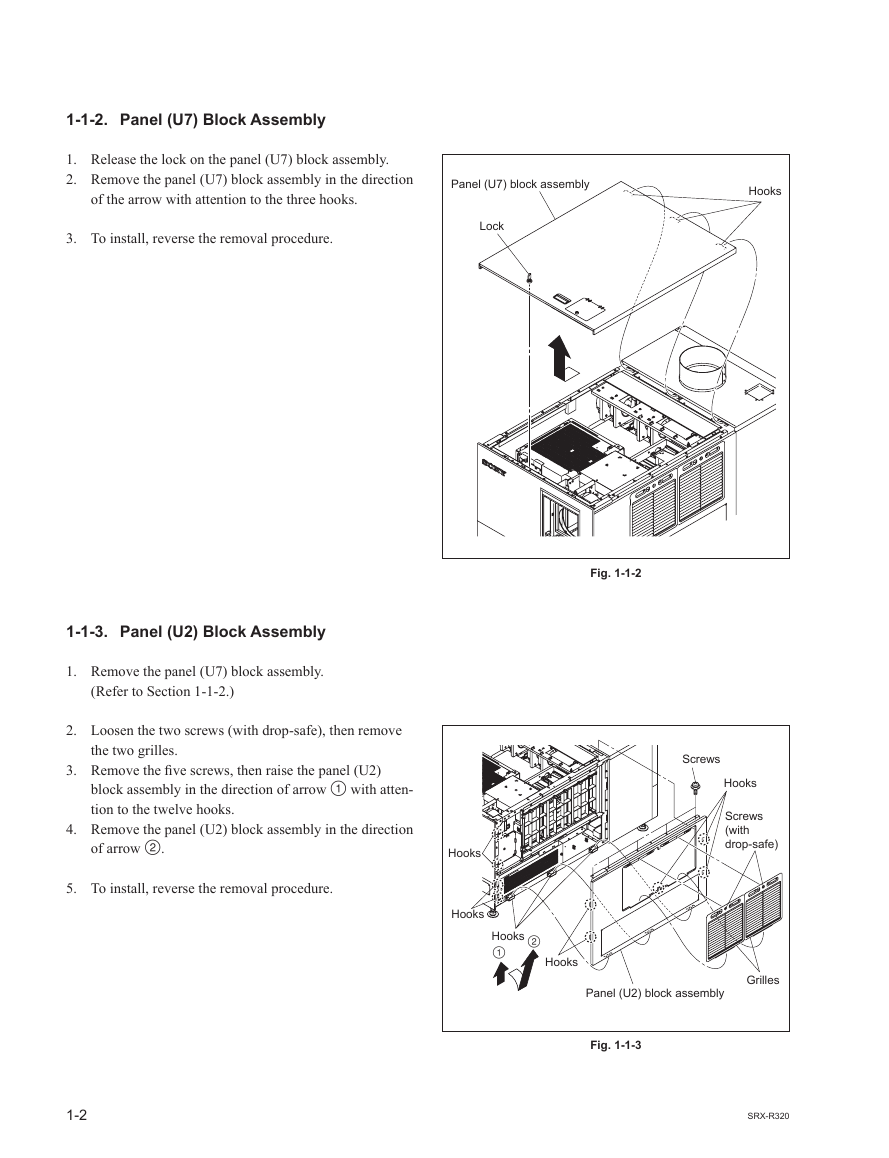
1-1-2. Panel (U7) Block Assembly 1. Release the lock on the panel (U7) block assembly. 2. Remove the panel (U7) block assembly in the direction of the arrow with attention to the three hooks. Panel (U7) block assembly Hooks 3. To install, reverse the removal procedure. Lock 1-1-3. Panel (U2) Block Assembly 1. Remove the panel (U7) block assembly. (Refer to Section 1-1-2.) 2. Loosen the two screws (with drop-safe), then remove the two grilles. 3. Remove the fi ve screws, then raise the panel (U2) block assembly in the direction of arrow  with atten- tion to the twelve hooks. 4. Remove the panel (U2) block assembly in the direction of arrow . 5. To install, reverse the removal procedure. Fig. 1-1-2 Hooks Hooks Hooks   Hooks Screws Hooks Screws (with drop-safe) Panel (U2) block assembly Grilles Fig. 1-1-3 1-2 SRX-R320
分享到:
收藏