4-440-785-14(1)
Digital Cinema
Projector Package
Operating Instructions
Before operating the unit, please read this manual and supplied Safety Regulations
thoroughly and retain it for future reference.
SRX-R515P
© 2013 Sony Corporation
�
Table of Contents
Please Read This First .............................................. 3
Notations Used in This Guide ................................ 3
Manual Structure ................................................... 3
About License ........................................................ 3
USB HDD and USB Memory Devices That can be
Used on INGEST PORT 1/2 of This Unit ........... 3
Recognized Folder Names ..................................... 3
Overview
Part Names and Functions ....................................... 4
Digital Cinema Projector SRX-R515 .................... 4
Digital Cinema Server XCT-S10 ........................... 6
Touch Panel Monitor LKRA-007 .......................... 7
Main Screen ........................................................... 9
Items to Check
Startup ..................................................................... 11
Turning on the Projector’s Main Power ............... 11
Starting up the Server .......................................... 11
Logging Into the System ...................................... 11
Starting the Projector ........................................... 13
Shutting Down the System ..................................... 13
Operations
Sequence of Operations .......................................... 14
Ingesting DCP .......................................................... 14
Ingesting from HDD via USB Connector ............ 14
Ingesting from HDD via CRU DATAPORT ........ 16
Ingesting via Network .......................................... 16
Ingesting KDM ........................................................ 17
Ingesting from a USB Flash Drive ....................... 17
Ingesting from a Network Folder ......................... 18
Playing Back CPL ................................................... 19
Calling up Screen Adjustment Data .................... 19
Selecting a CPL ................................................... 19
CPL Playback Operations .................................... 20
Creating an SPL ...................................................... 21
Creating an SPL ................................................... 21
Setting an Intermission in the SPL ...................... 23
Triggering SPL Playback Using GPI Signals ...... 24
Playing Back a SPL ................................................. 25
Selecting an SPL .................................................. 25
SPL Playback Operations .................................... 25
Creating a Schedule ................................................ 25
Creating a Schedule ............................................. 25
Importing/Exporting Schedules ........................... 26
Projecting Images Using an External Playback
Device ....................................................................... 27
Manually Controlling Theater Facilities ............... 28
2 Table of Contents
Others
Attaching and Removing the Lens ........................ 29
Removing the Lens .............................................. 29
Attaching the Lens ............................................... 30
Replacing the Lens Using the Lens Change
Table ......................................................................... 31
How to Read the Indicators ................................... 34
Troubleshooting ....................................................... 36
Specifications ........................................................... 37
Digital Cinema Projector SRX-R515 .................. 37
Digital Cinema Server XCT-S10 ......................... 38
Touch Panel Monitor LKRA-007 ........................ 38
Trademarks
The terms HDMI and HDMI High-Definition
Multimedia Interface, and the HDMI Logo are
trademarks or registered trademarks of HDMI Licensing
LLC in the United States and other countries.
Other products or system names appearing in this
document are trademarks or registered trademarks of
their respective owners.
Further, the ® or ™ symbols are not used in the text.
Reproduction or duplication, in whole or part, of the
operation manual supplied with the system without the
authorization of the right holder is prohibited under
copyright law.
Sony assumes no responsibility for damages, loss of
income, or any claims from a third party arising out of
use of the system.
Note that the specifications of the system are subject to
change for improvement without prior notice.
�
USB HDD and USB Memory Devices
That can be Used on INGEST PORT
1/2 of This Unit
USB HDD and USB memory devices that can be used on
INGEST PORT 1/2 of this unit are as follows.
USB 2.0/3.0 (bus power capacity up to 1 A)
Do not insert a bus-powered USB HDD and a USB
memory device into the two ports at the same time.
USB HDD compatible file system
ext2, ext3
(Operation is not guaranteed for all types of USB HDD and
USB memory devices.)
Recognized Folder Names
Regarding the external directories (USB HDD, USB
memory devices, network folders, etc.) that are connected
to the unit, only folder names that consist of alphanumeric
characters will be recognized by the unit.
Please Read This First
Notations Used in This Guide
In this guide, SRX-R515 Digital Cinema Projector is
referred to as the “projector”, XCT-S10 Digital Cinema
Server is referred to as the “server”, and LKRA-007 Touch
Panel Monitor is referred to as the “touch panel monitor.”
Manual Structure
The following manuals are provided for the SRX-R515P
depending on the application.
Safety Regulations
This includes safety instructions and precautions for using
the SRX-R515P.
Installation Manual
This includes instructions on how to install the unit,
information on default settings, and instructions on how to
adjust the unit. Be sure to refer to this manual whenever
you need to change settings or readjust the unit after
installation.
Operating Instructions (this guide)
This includes instructions for screening controls in a
theater, how to create a screening schedule, how to change
lenses, projector part names, and product specifications.
Be sure to refer to this guide for instructions on daily
usage.
Maintenance Manual
This includes information such as instructions on periodic
inspection, maintenance, and cleaning.
Service Manual
This is intended for use by service personnel and includes
information on diagnosing malfunctions and instructions
on repair.
About License
Refer to “Software License Agreement.”
Please Read This First
3
�
O
v
e
r
v
e
w
i
Overview
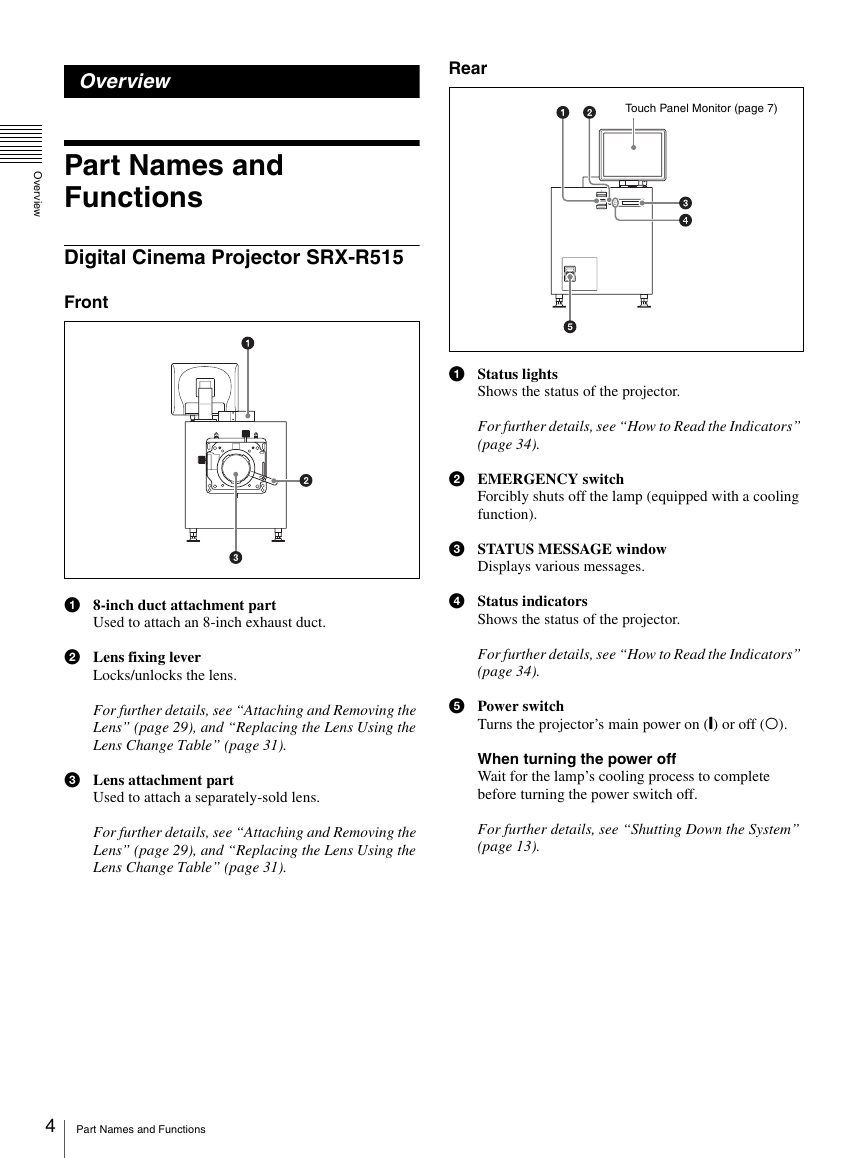
Rear
Touch Panel Monitor (page 7)
Part Names and
Functions
Digital Cinema Projector SRX-R515
Front
a Status lights
Shows the status of the projector.
For further details, see “How to Read the Indicators”
(page 34).
b EMERGENCY switch
Forcibly shuts off the lamp (equipped with a cooling
function).
c STATUS MESSAGE window
Displays various messages.
d Status indicators
Shows the status of the projector.
For further details, see “How to Read the Indicators”
(page 34).
e Power switch
Turns the projector’s main power on (|) or off (a).
When turning the power off
Wait for the lamp’s cooling process to complete
before turning the power switch off.
For further details, see “Shutting Down the System”
(page 13).
a 8-inch duct attachment part
Used to attach an 8-inch exhaust duct.
b Lens fixing lever
Locks/unlocks the lens.
For further details, see “Attaching and Removing the
Lens” (page 29), and “Replacing the Lens Using the
Lens Change Table” (page 31).
c Lens attachment part
Used to attach a separately-sold lens.
For further details, see “Attaching and Removing the
Lens” (page 29), and “Replacing the Lens Using the
Lens Change Table” (page 31).
4 Part Names and Functions
�
O
v
e
r
v
e
w
i
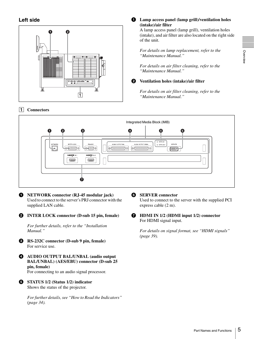
Left side
a Lamp access panel (lamp grill)/ventilation holes
(intake)/air filter
A lamp access panel (lamp grill), ventilation holes
(intake), and air filter are also located on the right side
of the unit.
For details on lamp replacement, refer to the
“Maintenance Manual.”
For details on air filter cleaning, refer to the
“Maintenance Manual.”
b Ventilation holes (intake)/air filter
For details on air filter cleaning, refer to the
“Maintenance Manual.”
A Connectors
Integrated Media Block (IMB)
a NETWORK connector (RJ-45 modular jack)
f SERVER connector
Used to connect to the server’s PRJ connector with the
supplied LAN cable.
Used to connect to the server with the supplied PCI
express cable (2 m).
b INTER LOCK connector (D-sub 15 pin, female)
g HDMI IN 1/2 (HDMI input 1/2) connector
For HDMI signal input.
For details on signal format, see “HDMI signals”
(page 39).
For further details, refer to the “Installation
Manual.”
c RS-232C connector (D-sub 9 pin, female)
For service use.
d AUDIO OUTPUT BAL/UNBAL (audio output
BAL/UNBAL) (AES/EBU) connector (D-sub 25
pin, female)
For connecting to an audio signal processor.
e STATUS 1/2 (Status 1/2) indicator
Shows the status of the projector.
For further details, see “How to Read the Indicators”
(page 34).
Part Names and Functions
5
�
O
v
e
r
v
e
w
i
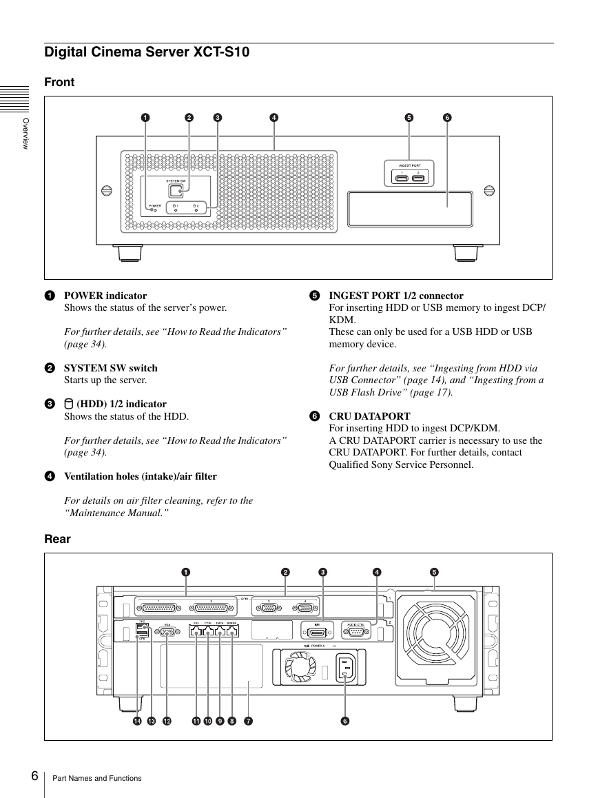
Digital Cinema Server XCT-S10
Front
a POWER indicator
Shows the status of the server’s power.
For further details, see “How to Read the Indicators”
(page 34).
b SYSTEM SW switch
Starts up the server.
c (HDD) 1/2 indicator
Shows the status of the HDD.
For further details, see “How to Read the Indicators”
(page 34).
d Ventilation holes (intake)/air filter
For details on air filter cleaning, refer to the
“Maintenance Manual.”
Rear
e INGEST PORT 1/2 connector
For inserting HDD or USB memory to ingest DCP/
KDM.
These can only be used for a USB HDD or USB
memory device.
For further details, see “Ingesting from HDD via
USB Connector” (page 14), and “Ingesting from a
USB Flash Drive” (page 17).
f CRU DATAPORT
For inserting HDD to ingest DCP/KDM.
A CRU DATAPORT carrier is necessary to use the
CRU DATAPORT. For further details, contact
Qualified Sony Service Personnel.
6 Part Names and Functions
�
O
v
e
r
v
e
w
i
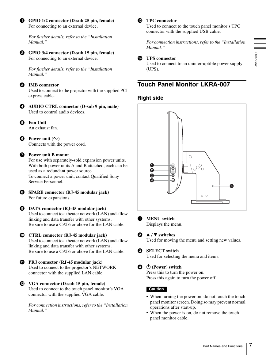
a GPIO 1/2 connector (D-sub 25 pin, female)
m TPC connector
For connecting to an external device.
For further details, refer to the “Installation
Manual.”
b GPIO 3/4 connector (D-sub 15 pin, female)
For connecting to an external device.
For further details, refer to the “Installation
Manual.”
c IMB connector
Used to connect to the projector with the supplied PCI
express cable.
d AUDIO CTRL connector (D-sub 9 pin, male)
Used to control audio devices.
e Fan Unit
An exhaust fan.
f Power unit (-)
Connects with the power cord.
g Power unit B mount
For use with separately-sold expansion power units.
With both power units A and B attached, each can be
used as a redundant power source.
To connect a power unit, contact Qualified Sony
Service Personnel.
h SPARE connector (RJ-45 modular jack)
For future expansions.
i DATA connector (RJ-45 modular jack)
Used to connect to a theater network (LAN) and allow
linking and data transfer with other systems.
Be sure to use a CAT6 or above for the LAN cable.
j CTRL connector (RJ-45 modular jack)
Used to connect to a theater network (LAN) and allow
linking and data transfer with other systems.
Be sure to use a CAT6 or above for the LAN cable.
k PRJ connector (RJ-45 modular jack)
Used to connect to the projector’s NETWORK
connector with the supplied LAN cable.
l VGA connector (D-sub 15 pin, female)
Used to connect to the touch panel monitor’s VGA
connector with the supplied VGA cable.
For connection instructions, refer to the “Installation
Manual.”
Used to connect to the touch panel monitor’s TPC
connector with the supplied USB cable.
For connection instructions, refer to the “Installation
Manual.”
n UPS connector
Used to connect to an uninterruptible power supply
(UPS).
Touch Panel Monitor LKRA-007
Right side
a MENU switch
Displays the menu.
b v / V switches
Used for moving the menu and setting new values.
c SELECT switch
Used for selecting the menu and items.
d 1 (Power) switch
Press this to turn the power on.
Press this again to turn the power off.
Caution
When turning the power on, do not touch the touch
panel monitor screen. Doing so may prevent normal
operations after start-up.
When the power is on, do not remove the touch
panel monitor cable.
Part Names and Functions
7
�
O
v
e
r
v
e
w
i
e Monitor stand
This is equipped with a tilt mechanism.
The monitor’s position can be adjusted in the up,
down, left, and right directions.
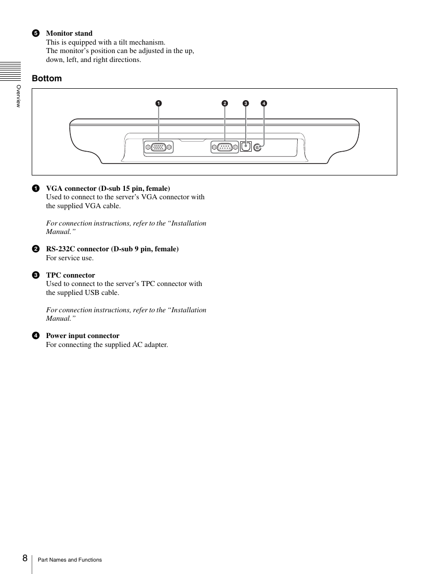
Bottom
a VGA connector (D-sub 15 pin, female)
Used to connect to the server’s VGA connector with
the supplied VGA cable.
For connection instructions, refer to the “Installation
Manual.”
b RS-232C connector (D-sub 9 pin, female)
For service use.
c TPC connector
Used to connect to the server’s TPC connector with
the supplied USB cable.
For connection instructions, refer to the “Installation
Manual.”
d Power input connector
For connecting the supplied AC adapter.
8 Part Names and Functions
�



 2023年江西萍乡中考道德与法治真题及答案.doc
 2012年重庆南川中考生物真题及答案.doc
 2013年江西师范大学地理学综合及文艺理论基础考研真题.doc
 2020年四川甘孜小升初语文真题及答案I卷.doc
 2020年注册岩土工程师专业基础考试真题及答案.doc
 2023-2024学年福建省厦门市九年级上学期数学月考试题及答案.doc
 2021-2022学年辽宁省沈阳市大东区九年级上学期语文期末试题及答案.doc
 2022-2023学年北京东城区初三第一学期物理期末试卷及答案.doc
 2018上半年江西教师资格初中地理学科知识与教学能力真题及答案.doc
 2012年河北国家公务员申论考试真题及答案-省级.doc
 2020-2021学年江苏省扬州市江都区邵樊片九年级上学期数学第一次质量检测试题及答案.doc
 2022下半年黑龙江教师资格证中学综合素质真题及答案.doc