logo资料库

Sierra的Q2687模块.pdf

第1页 / 共147页
第2页 / 共147页
第3页 / 共147页
第4页 / 共147页
第5页 / 共147页
第6页 / 共147页
第7页 / 共147页
第8页 / 共147页
资料共147页,剩余部分请下载后查看
Contents
List of Figures
List of Tables
1. Introduction
1.1. Physical Dimensions
1.2. General Features
1.3. GSM/GPRS/EGPRS Features
1.4. Interfaces
1.5. Operating System
1.6. Connection Interfaces
1.7. Environment and Mechanics
1.7.1. RoHS Directive Compliant
1.7.2. Disposing of the Product
2. Functional Specifications
2.1. Functional Architecture
2.1.1. RF Functionalities
2.1.2. Baseband Functionalities
2.2. Operating System
3. Technical Specifications
3.1. Power Supply
3.1.1. Power Supply Pin-Out
3.1.2. Start-Up Current
3.1.3. Decoupling of Power Supply Signals
3.2. Mechanical Specifications
3.3. Firmware Upgrade
3.4. Conformance with ATEX 94/9/CE Directive
4. Interfaces
4.1. General Purpose Connector (GPC)
4.1.1. Pin Description
4.1.2. Pin Out Differences
4.2. Electrical Information for Digital I/O
4.3. General Purpose Input/Output
4.3.1. Pin Description
4.4. Serial Interface
4.4.1. SPI Bus
4.4.1.1. Characteristics
4.4.1.2. SPI Configuration
4.4.1.3. SPI Waveforms
4.4.1.4. SPI1 Pin Description
4.4.1.5. SPI2 Pin Description
4.4.1.6. Application
4.4.1.6.1. 3-wire Application
4.4.1.6.2. 4-wire Application
4.4.1.6.3. 5-wire Application
4.4.2. I2C Bus
4.4.2.1. I2C Waveforms
4.4.2.2. I2C Pin Description
4.4.2.3. Application
4.5. Parallel Interface
4.5.1. Pin Description
4.5.2. Electrical Characteristics
4.5.3. Asynchronous Access
4.5.4. Synchronous Access
4.5.5. Additional Information Regarding Address Size Bus
4.5.6. Application
4.6. Keyboard Interface
4.6.1. Pin Description
4.6.2. Application
4.7. Main Serial Link (UART1)
4.7.1. Pin Description
4.7.2. Level Shifter Implementation
4.7.2.1. Recommended Components
4.7.3. V24/CMOS Possible Designs
4.7.4. 5-wire Serial Interface
4.7.5. 4-wire Serial Interface
4.7.6. 2-wire Serial Interface
4.8. Auxiliary Serial Link (UART2)
4.8.1. Pin Description
4.8.2. Level Shifter Implementation
4.8.2.1. Recommended Components
4.8.3. 4-wire Serial Interface
4.8.4. 2-wire Serial Interface
4.9. SIM Interface
4.9.1. Pin Description
4.9.2. Electrical Characteristics
4.9.3. Application
4.9.3.1. SIM Socket Pin Description
4.9.3.2. Recommended Components
4.9.4. Embedded SIM
4.9.4.1. AT Commands for SIM Selection
4.10. USB 2.0 Interface
4.10.1. Pin Description
4.10.2. Electrical Characteristics
4.10.3. Application
4.10.3.1. Recommended Components
4.11. RF Interface
4.11.1. RF Connections
4.11.1.1. UFL Connector
4.11.1.2. Soldered Solution
4.11.1.3. Precidip Connector
4.11.2. RF Performance
4.11.3. Antenna Specifications
4.11.3.1. Application
4.12. Analog Audio Interface
4.12.1. Pin Description
4.12.2. Microphone Features
4.12.2.1. MIC1 Microphone Input
4.12.2.1.1. MIC1 Differential Connection Example
4.12.2.1.2. MIC1 Single-Ended Connection Example
4.12.2.2. MIC2 Microphone Input
4.12.2.2.1. MIC2 Differential Connection Example
4.12.2.2.2. MIC2 Single-Ended Connection Example
4.12.3. Speaker Features
4.12.3.1. Speakers Output Power
4.12.3.2. SPK1 Speaker Output
4.12.3.3. SPK2 Speaker Output
4.12.3.4. Differential Connection Example
4.12.3.5. Single-Ended Connection Example
4.12.3.6. Recommended Characteristics
4.13. Digital Audio Interface (PCM)
4.13.1. PCM Waveforms
4.13.2. Pin Description
4.14. Battery Charging Interface
4.14.1. Charging Algorithms
4.14.1.1. Ni-Cd/Ni-Mh Charging Algorithm
4.14.1.2. Li-Ion Charging Algorithm
4.14.1.2.1. Pulse Appearance in Phase 2
4.14.1.2.2. Rest in Between Pulses in Phase 3
4.14.2. Pre-Charging
4.14.3. Temperature Monitoring
4.14.4. Application
4.14.4.1. Temperature Computation Method
4.14.5. Charger Recommendations
4.15. Temperature Sensor Interface
5. Signals and Indicators
5.1. ON/~OFF Signal
5.1.1. Pin Description
5.1.2. Electrical Characteristics
5.1.3. Power-ON
5.1.4. Power-OFF
5.1.5. Application
5.1.6. When ON/~OFF is tied to VBATT
5.2. Reset Signal (~RESET)
5.2.1. Reset Sequence
5.2.2. Pin Description
5.2.3. Electrical Characteristics
5.2.4. Application
5.3. BOOT Signal
5.3.1. Pin Description
5.4. BAT-RTC (Backup Battery)
5.4.1. Pin Description
5.4.2. Electrical Characteristics
5.4.3. Application
5.4.3.1. Super Capacitor
5.4.3.2. Non-Rechargeable Battery
5.4.3.3. Rechargeable Battery
5.5. Buzzer Output
5.5.1. Pin Description
5.5.2. Electrical Characteristics
5.5.3. Application
5.5.3.1. Recommended Characteristics
5.6. External Interrupt
5.6.1. Pin Description
5.6.2. Electrical Characteristics
5.6.3. Application
5.7. VCC_2V8 and VCC_1V8 Output
5.7.1. Pin Description
5.7.2. Electrical Characteristics
5.8. FLASH-LED (LED0)
5.8.1. Pin Description
5.8.2. Electrical Characteristics
5.8.3. Application
5.9. Analog to Digital Converter
5.9.1. Pin Description
5.9.2. Electrical Characteristics
5.10. Digital to Analog Converter
5.10.1. Pin Description
5.10.2. Electrical Characteristics
6. Power Consumption
6.1. Power Consumption without the Sierra Wireless Software Suite
6.2. Power Consumption with the Sierra Wireless Software Suite
7. Consumption Measurement Procedure
7.1. Hardware Configuration
7.1.1. Equipments Used
7.1.2. Q Series Development Kit Board v3
7.1.3. SIM Cards
7.2. Software Configuration
7.2.1. Embedded Module Configuration
7.2.2. Equipment Configuration
8. Reliability Compliance and Recommended Standards
8.1. Reliability Compliance
8.2. Applicable Standards Listing
8.3. Environmental Specifications
8.3.1. Function Status Classification
8.4. Reliability Prediction Model
8.4.1. Life Stress Tests
8.4.2. Environmental Resistance Stress Tests
8.4.3. Corrosive Resistance Stress Tests
8.4.4. Thermal Resistance Cycle Stress Tests
8.4.5. Mechanical Resistance Stress Tests
8.4.6. Handling Resistance Stress Tests
9. Design Guidelines
9.1. General Rules and Constraints
9.2. Power Supply
9.3. Antenna
9.4. Layout/Pads Design
9.5. Routing Constraints
9.5.1. System Connector
9.5.2. Power Supply
9.5.2.1. Ground Plane and Shielding Connection
9.5.3. SIM Interface
9.5.4. Audio Circuit
9.5.5. RF Circuit
9.5.5.1. UFL/SMA Connector
9.5.5.2. Coaxial Cable
9.5.5.3. Precidip Connector
9.6. EMC and ESD Recommendations
9.7. Mechanical Integration
9.8. Operating System Upgrade
10. Embedded Testability
10.1. Serial Link Access
10.2. RF Output Accessibility
11. Connector and Peripheral Device References
11.1. General Purpose Connector
11.2. SIM Card Reader
11.3. Microphone
11.4. Speaker
11.5. Antenna Cable
11.6. RF board-to-board connector
11.7. GSM antenna
11.8. Buzzer
12. Certification Compliance and Recommended Standards
12.1. Certification Compliance
12.2. Applicable Standards Listing
13. References
13.1. Web Site Support
13.2. Reference Documents
13.2.1. Sierra Wireless Software Documentation
13.2.2. Firmware Documentation
13.2.3. Hardware Documentation
13.2.4. Other Sierra Wireless Documentation
13.2.5. Other Related Documentation
13.3. List of Abbreviations
14. Safety Recommendations (For Information Only)
14.1. RF Safety
14.1.1. General
14.1.2. Exposure to RF Energy
14.1.3. Efficient Terminal Operation
14.1.4. Antenna Care and Replacement
14.2. General Safety
14.2.1. Driving
14.2.2. Electronic Devices
14.2.3. Vehicle Electronic Equipment
14.2.4. Medical Electronic Equipment
14.2.5. Aircraft
14.2.6. Children
14.2.7. Blasting Areas
14.2.8. Potentially Explosive Atmospheres
Product Technical Specification and Customer Design Guideline AirPrime Q2687 Refreshed WA_DEV_Q26RD_PTS_001 007 August 17, 2011
Product Technical Specification and Customer Design Guideline Important Notice Due to the nature of wireless communications, transmission and reception of data can never be guaranteed. Data may be delayed, corrupted (i.e., have errors) or be totally lost. Although significant delays or losses of data are rare when wireless devices such as the Sierra Wireless modem are used in a normal manner with a well-constructed network, the Sierra Wireless modem should not be used in situations where failure to transmit or receive data could result in damage of any kind to the user or any other party, including but not limited to personal injury, death, or loss of property. Sierra Wireless accepts no responsibility for damages of any kind resulting from delays or errors in data transmitted or received using the Sierra Wireless modem, or for failure of the Sierra Wireless modem to transmit or receive such data. Safety and Hazards Do not operate the Sierra Wireless modem in areas where blasting is in progress, where explosive atmospheres may be present, near medical equipment, near life support equipment, or any equipment which may be susceptible to any form of radio interference. In such areas, the Sierra Wireless modem MUST BE POWERED OFF. The Sierra Wireless modem can transmit signals that could interfere with this equipment. Do not operate the Sierra Wireless modem in any aircraft, whether the aircraft is on the ground or in flight. In aircraft, the Sierra Wireless modem MUST BE POWERED OFF. When operating, the Sierra Wireless modem can transmit signals that could interfere with various onboard systems. Note: Some airlines may permit the use of cellular phones while the aircraft is on the ground and the door is open. Sierra Wireless modems may be used at this time. The driver or operator of any vehicle should not operate the Sierra Wireless modem while in control of a vehicle. Doing so will detract from the driver or operator’s control and operation of that vehicle. In some states and provinces, operating such communications devices while in control of a vehicle is an offence. Limitations of Liability This manual is provided “as is”. Sierra Wireless makes no warranties of any kind, either expressed or implied, including any implied warranties of merchantability, fitness for a particular purpose, or noninfringement. The recipient of the manual shall endorse all risks arising from its use. The information in this manual is subject to change without notice and does not represent a commitment on the part of Sierra Wireless. SIERRA WIRELESS AND ITS AFFILIATES SPECIFICALLY DISCLAIM LIABILITY FOR ANY AND ALL DIRECT, INDIRECT, SPECIAL, GENERAL, INCIDENTAL, CONSEQUENTIAL, PUNITIVE OR EXEMPLARY DAMAGES INCLUDING, BUT NOT LIMITED TO, LOSS OF PROFITS OR REVENUE OR ANTICIPATED PROFITS OR REVENUE ARISING OUT OF THE USE OR INABILITY TO USE ANY SIERRA WIRELESS PRODUCT, EVEN IF SIERRA WIRELESS AND/OR ITS AFFILIATES HAS BEEN ADVISED OF THE POSSIBILITY OF SUCH DAMAGES OR THEY ARE FORESEEABLE OR FOR CLAIMS BY ANY THIRD PARTY. Notwithstanding the foregoing, in no event shall Sierra Wireless and/or its affiliates aggregate liability arising under or in connection with the Sierra Wireless product, regardless of the number of events, occurrences, or claims giving rise to liability, be in excess of the price paid by the purchaser for the Sierra Wireless product. WA_DEV_Q26RD_PTS_001 Rev 007 August 17, 2011 2
Product Technical Specification and Customer Design Guideline Patents This product may contain technology developed by or for Sierra Wireless Inc. This product includes technology licensed from QUALCOMM® 3G. This product is manufactured or sold by Sierra Wireless Inc. or its affiliates under one or more patents licensed from InterDigital Group. Copyright © 2011 Sierra Wireless. All rights reserved. Trademarks AirCard® and Watcher® are registered trademarks of Sierra Wireless. Sierra Wireless™, AirPrime™, AirLink™, AirVantage™ and the Sierra Wireless logo are trademarks of Sierra Wireless. , ®, inSIM®, WAVECOM®, WISMO®, Wireless Microprocessor®, , Wireless CPU®, Open AT® are filed or registered trademarks of Sierra Wireless S.A. in France and/or in other countries. Windows® and Windows Vista® are registered trademarks of Microsoft Corporation. Macintosh and Mac OS are registered trademarks of Apple Inc., registered in the U.S. and other countries. QUALCOMM® is a registered trademark of QUALCOMM Incorporated. Used under license. Other trademarks are the property of the respective owners. Contact Information 1-604-232-1488 8:00 AM to 5:00 PM Pacific Time sales@sierrawireless.com Sales Desk: Post: Phone: Hours: E-mail: Sierra Wireless 13811 Wireless Way Richmond, BC Canada V6V 3A4 Fax: 1-604-231-1109 Web: www.sierrawireless.com Consult our website for up-to-date product descriptions, documentation, application notes, firmware upgrades, troubleshooting tips, and press releases: www.sierrawireless.com WA_DEV_Q26RD_PTS_001 Rev 007 August 17, 2011 3
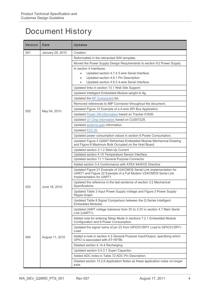
Product Technical Specification and Customer Design Guideline Document History Version Date Updates 001 January 28, 2010 002 May 04, 2010 003 June 18, 2010 004 August 11, 2010 Creation Reformatted in the rebranded SWI template. Moved the Power Supply Design Requirements to section 9.2 Power Supply In section 4 Interfaces:  Updated section 4.7.4 5-wire Serial Interface  Updated section 4.8.1 Pin Description  Updated section 4.8.3 4-wire Serial Interface Updated links in section 13.1 Web Site Support. Updated Intelligent Embedded Module weight to 8g. Updated the RF Component list. Removed references to IMP Connector throughout the document. Updated Figure 10 Example of a 4-wire SPI Bus Application. Updated Power ON information based on Tracker 01626. Updated U1 Chip information based on CUS57225. Updated antenna gain information. Updated FCC ID. Updated power consumption values in section 6 Power Consumption. Updated Figure 5 Q2687 Refreshed Embedded Module Mechanical Drawing and Figure 6 Maximum Bulk Occupied on the Host Board. Updated section 3.1.2 Start-Up Current Updated section 4.15 Temperature Sensor Interface Updated section 11.1 General Purpose Connector Added section 3.4 Conformance with ATEX 94/9/CE Directive Updated Figure 21 Example of V24/CMOS Serial Link Implementation for UART1 and Figure 22 Example of a Full Modem V24/CMOS Serial Link Implementation for UART1 Updated the reference in the last sentence of section 3.2 Mechanical Specifications Updated Table 3 Input Power Supply Voltage and Figure 3 Power Supply Ripple Graph. Updated Table 8 Signal Comparison between the Q Series Intelligent Embedded Modules. Updated UART voltage tolerance from 3V to 3.3V in section 4.7 Main Serial Link (UART1). Added note for entering Sleep Mode in sections 7.2.1 Embedded Module Configuration and 6 Power Consumption. Updated the signal name of pin 22 from GPIO31/SPI1 Load to GPIO31/SPI1- Load. Added a note in section 4.3 General Purpose Input/Output, specifying which GPIO is associated with AT+WTBI. Deleted section 4.14.4 Recharging. Updated section 5.4.3.1 Super Capacitor. Added ADC index in Table 72 ADC Pin Description. Deleted section 13.2.6 Application Notes as these application notes no longer exits. WA_DEV_Q26RD_PTS_001 Rev 007 August 17, 2011 4
Product Technical Specification and Customer Design Guideline Version Date Updates 005 October 27, 2010 006 June 20, 2011 007 August 17, 2011 Deleted Figure 69. Updated Table 75 Electrical Characteristics of the DAC. Added information for the ESIM version, Q26SM703RD, throughout the document which includes the following:  Added section 4.9.4 Embedded SIM  Added voltage start-up note after Table 3 Input Power Supply Voltage and Table 5 Current Start-Up  Added additional information in Table 10 Electrical Characteristic of a 1.8 Volt Type (1V8) Digital I/O, Table 49 Electrical Characteristics of the Temperature Monitoring Feature, and Table 69 FLASH-LED Status  Added Table 62 Electrical Characteristics of the BAT-RTC Interface (for the Q26SM703RD)  Added Table 77 Power Consumption Without the Sierra Wireless Software Suite for the Q26SM703RD; Typical Values Added section 5.1.6 When ON/~OFF is tied to VBATT. Added additional external interrupts in the following tables:       Table 7 General Purpose Connector Pin Description Table 13 GPIO Pin Description Table 25 UART1 Pin Description Table 26 UART2 Pin Description Table 65 External Interrupt Pin Description Table 66 Electrical Characteristics of the External Input/Interrupt Updated the power consumption values in Table 76 Power Consumption Without the Sierra Wireless Software Suite for non-ESIM modules; Typical Values. Added a note in sections 14.2.7 and 14.2.8 for ATEX compliance. WA_DEV_Q26RD_PTS_001 Rev 007 August 17, 2011 5
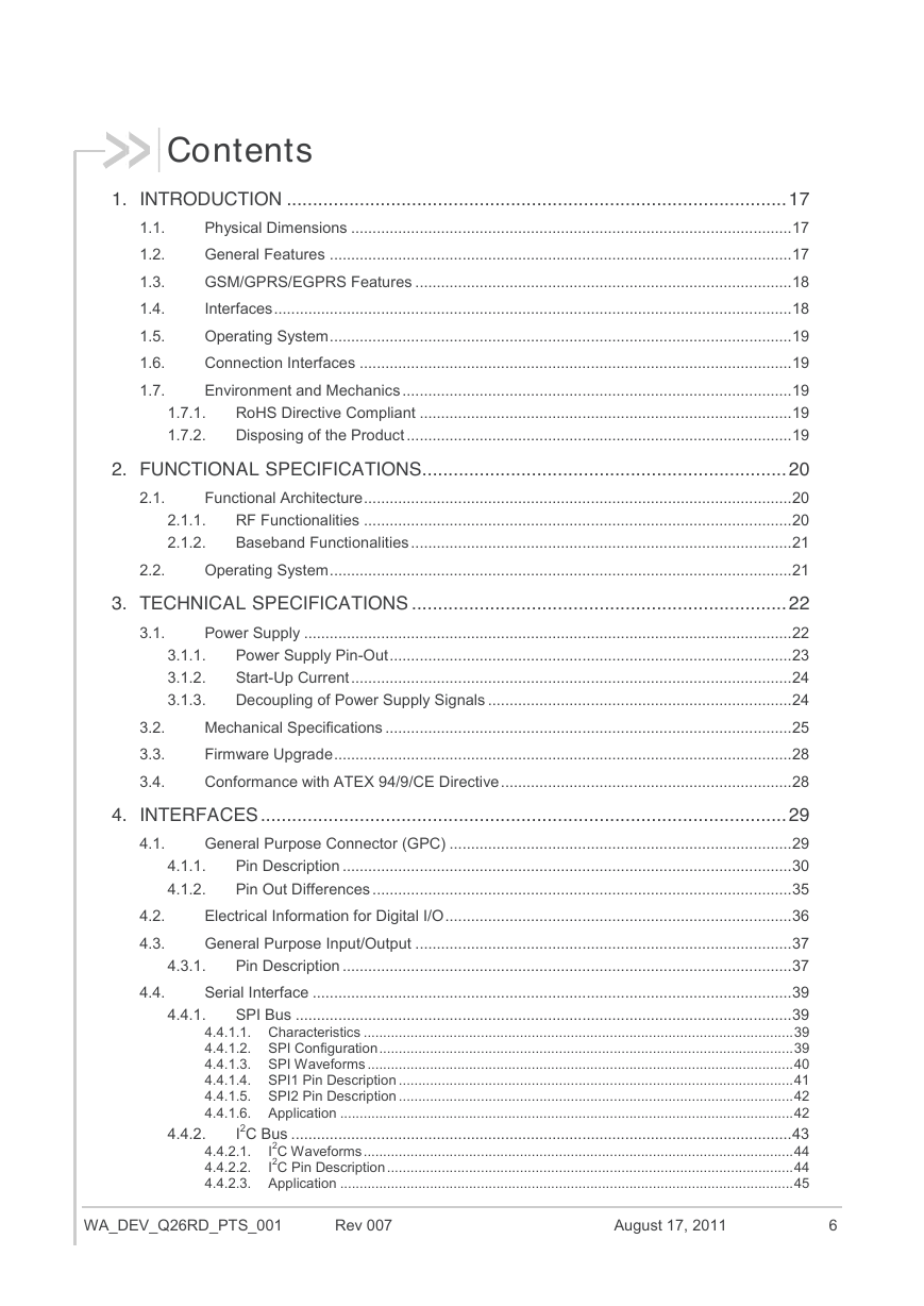
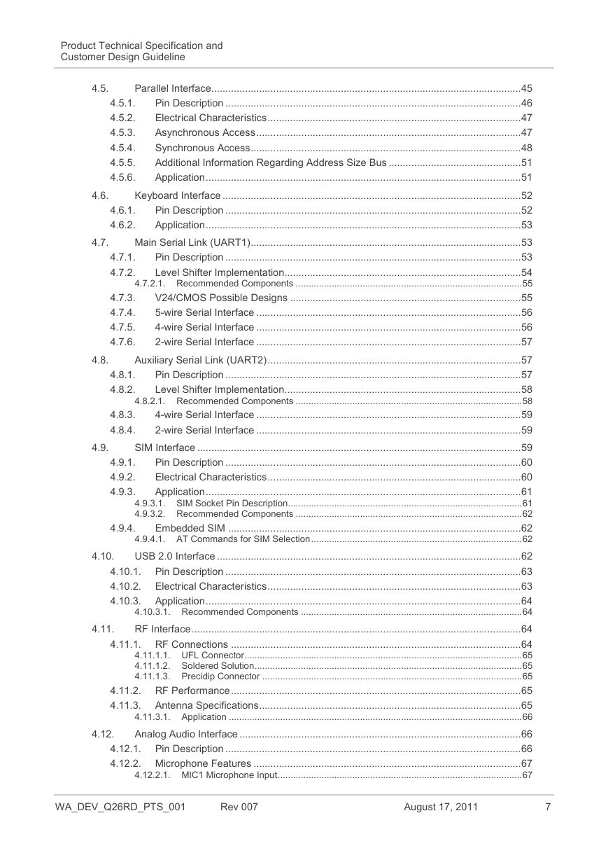
Contents 1.1. 1.2. 1.3. 1.4. 1.5. 1.6. 1.7. 1. INTRODUCTION ................................................................................................ 17 Physical Dimensions ....................................................................................................... 17 General Features ............................................................................................................ 17 GSM/GPRS/EGPRS Features ........................................................................................ 18 Interfaces ......................................................................................................................... 18 Operating System ............................................................................................................ 19 Connection Interfaces ..................................................................................................... 19 Environment and Mechanics ........................................................................................... 19 RoHS Directive Compliant ....................................................................................... 19 Disposing of the Product .......................................................................................... 19 1.7.1. 1.7.2. 2.1. 2. FUNCTIONAL SPECIFICATIONS ...................................................................... 20 Functional Architecture .................................................................................................... 20 RF Functionalities .................................................................................................... 20 Baseband Functionalities ......................................................................................... 21 Operating System ............................................................................................................ 21 2.1.1. 2.1.2. 2.2. 3.1. 3.1.1. 3.1.2. 3.1.3. 3. TECHNICAL SPECIFICATIONS ........................................................................ 22 Power Supply .................................................................................................................. 22 Power Supply Pin-Out .............................................................................................. 23 Start-Up Current ....................................................................................................... 24 Decoupling of Power Supply Signals ....................................................................... 24 Mechanical Specifications ............................................................................................... 25 Firmware Upgrade ........................................................................................................... 28 Conformance with ATEX 94/9/CE Directive .................................................................... 28 3.2. 3.3. 3.4. 4.4. 4.3.1. 4.4.1. 4.1. 4.2. 4.3. 4.1.1. 4.1.2. 4. INTERFACES ..................................................................................................... 29 General Purpose Connector (GPC) ................................................................................ 29 Pin Description ......................................................................................................... 30 Pin Out Differences .................................................................................................. 35 Electrical Information for Digital I/O ................................................................................. 36 General Purpose Input/Output ........................................................................................ 37 Pin Description ......................................................................................................... 37 Serial Interface ................................................................................................................ 39 SPI Bus .................................................................................................................... 39 4.4.1.1. Characteristics .............................................................................................................. 39 4.4.1.2. SPI Configuration .......................................................................................................... 39 4.4.1.3. SPI Waveforms ............................................................................................................. 40 4.4.1.4. SPI1 Pin Description ..................................................................................................... 41 4.4.1.5. SPI2 Pin Description ..................................................................................................... 42 4.4.1.6. Application .................................................................................................................... 42 I2C Bus ..................................................................................................................... 43 I2C Waveforms .............................................................................................................. 44 4.4.2.1. I2C Pin Description ........................................................................................................ 44 4.4.2.2. 4.4.2.3. Application .................................................................................................................... 45 4.4.2. WA_DEV_Q26RD_PTS_001 Rev 007 August 17, 2011 6
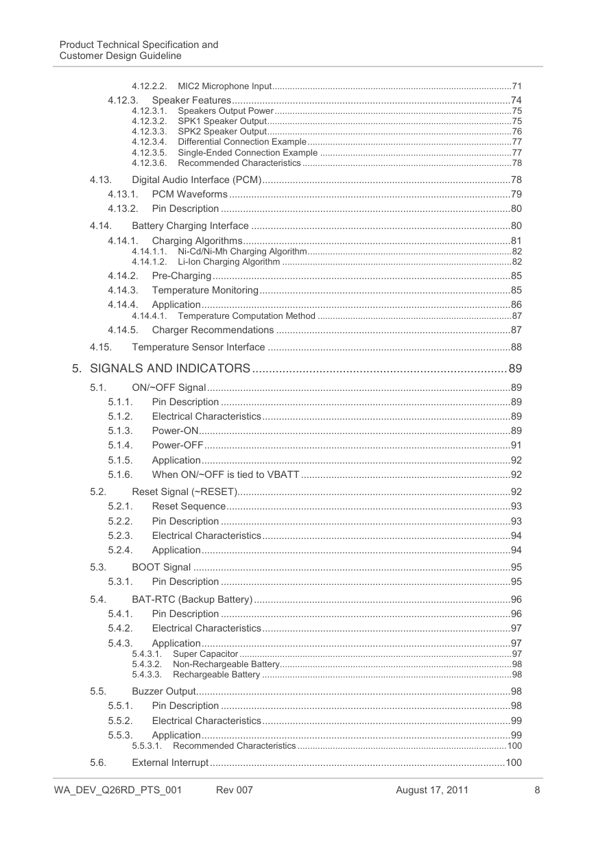
Product Technical Specification and Customer Design Guideline 4.6.1. 4.6.2. 4.7.1. 4.7.2. 4.7.3. 4.7.4. 4.7.5. 4.7.6. 4.5.1. 4.5.2. 4.5.3. 4.5.4. 4.5.5. 4.5.6. Parallel Interface.............................................................................................................. 45 Pin Description ......................................................................................................... 46 Electrical Characteristics .......................................................................................... 47 Asynchronous Access .............................................................................................. 47 Synchronous Access ................................................................................................ 48 Additional Information Regarding Address Size Bus ............................................... 51 Application ................................................................................................................ 51 Keyboard Interface .......................................................................................................... 52 Pin Description ......................................................................................................... 52 Application ................................................................................................................ 53 Main Serial Link (UART1) ................................................................................................ 53 Pin Description ......................................................................................................... 53 Level Shifter Implementation.................................................................................... 54 4.7.2.1. Recommended Components ........................................................................................ 55 V24/CMOS Possible Designs .................................................................................. 55 5-wire Serial Interface .............................................................................................. 56 4-wire Serial Interface .............................................................................................. 56 2-wire Serial Interface .............................................................................................. 57 Auxiliary Serial Link (UART2) .......................................................................................... 57 Pin Description ......................................................................................................... 57 Level Shifter Implementation.................................................................................... 58 4.8.2.1. Recommended Components ........................................................................................ 58 4-wire Serial Interface .............................................................................................. 59 2-wire Serial Interface .............................................................................................. 59 SIM Interface ................................................................................................................... 59 Pin Description ......................................................................................................... 60 Electrical Characteristics .......................................................................................... 60 Application ................................................................................................................ 61 4.9.3.1. SIM Socket Pin Description ........................................................................................... 61 4.9.3.2. Recommended Components ........................................................................................ 62 Embedded SIM ........................................................................................................ 62 4.9.4.1. AT Commands for SIM Selection .................................................................................. 62 USB 2.0 Interface ............................................................................................................ 62 4.10.1. Pin Description ......................................................................................................... 63 4.10.2. Electrical Characteristics .......................................................................................... 63 4.10.3. Application ................................................................................................................ 64 4.10.3.1. Recommended Components ...................................................................................... 64 RF Interface ..................................................................................................................... 64 4.11.1. RF Connections ....................................................................................................... 64 4.11.1.1. UFL Connector ............................................................................................................ 65 4.11.1.2. Soldered Solution ........................................................................................................ 65 4.11.1.3. Precidip Connector ..................................................................................................... 65 4.11.2. RF Performance ....................................................................................................... 65 4.11.3. Antenna Specifications ............................................................................................. 65 4.11.3.1. Application .................................................................................................................. 66 Analog Audio Interface .................................................................................................... 66 4.12.1. Pin Description ......................................................................................................... 66 4.12.2. Microphone Features ............................................................................................... 67 4.12.2.1. MIC1 Microphone Input ............................................................................................... 67 4.8.1. 4.8.2. 4.8.3. 4.8.4. 4.9.1. 4.9.2. 4.9.3. 4.9.4. 4.5. 4.6. 4.7. 4.8. 4.9. 4.10. 4.11. 4.12. WA_DEV_Q26RD_PTS_001 Rev 007 August 17, 2011 7
Product Technical Specification and Customer Design Guideline 4.12.2.2. MIC2 Microphone Input ............................................................................................... 71 4.12.3. Speaker Features ..................................................................................................... 74 4.12.3.1. Speakers Output Power .............................................................................................. 75 4.12.3.2. SPK1 Speaker Output ................................................................................................. 75 4.12.3.3. SPK2 Speaker Output ................................................................................................. 76 4.12.3.4. Differential Connection Example ................................................................................. 77 4.12.3.5. Single-Ended Connection Example ............................................................................ 77 4.12.3.6. Recommended Characteristics ................................................................................... 78 Digital Audio Interface (PCM) .......................................................................................... 78 4.13.1. PCM Waveforms ...................................................................................................... 79 4.13.2. Pin Description ......................................................................................................... 80 Battery Charging Interface .............................................................................................. 80 4.14.1. Charging Algorithms ................................................................................................. 81 4.14.1.1. Ni-Cd/Ni-Mh Charging Algorithm ................................................................................. 82 4.14.1.2. Li-Ion Charging Algorithm ........................................................................................... 82 4.14.2. Pre-Charging ............................................................................................................ 85 4.14.3. Temperature Monitoring ........................................................................................... 85 4.14.4. Application ................................................................................................................ 86 4.14.4.1. Temperature Computation Method ............................................................................. 87 4.14.5. Charger Recommendations ..................................................................................... 87 Temperature Sensor Interface ........................................................................................ 88 4.13. 4.14. 4.15. 5.1. 5.2. 5.2.1. 5.2.2. 5.2.3. 5.2.4. 5. SIGNALS AND INDICATORS ............................................................................ 89 ON/~OFF Signal .............................................................................................................. 89 Pin Description ......................................................................................................... 89 5.1.1. Electrical Characteristics .......................................................................................... 89 5.1.2. Power-ON................................................................................................................. 89 5.1.3. Power-OFF ............................................................................................................... 91 5.1.4. 5.1.5. Application ................................................................................................................ 92 5.1.6. When ON/~OFF is tied to VBATT ............................................................................ 92 Reset Signal (~RESET)................................................................................................... 92 Reset Sequence ....................................................................................................... 93 Pin Description ......................................................................................................... 93 Electrical Characteristics .......................................................................................... 94 Application ................................................................................................................ 94 BOOT Signal ................................................................................................................... 95 Pin Description ......................................................................................................... 95 BAT-RTC (Backup Battery) ............................................................................................. 96 Pin Description ......................................................................................................... 96 Electrical Characteristics .......................................................................................... 97 Application ................................................................................................................ 97 5.4.3.1. Super Capacitor ............................................................................................................ 97 5.4.3.2. Non-Rechargeable Battery ............................................................................................ 98 5.4.3.3. Rechargeable Battery ................................................................................................... 98 Buzzer Output.................................................................................................................. 98 Pin Description ......................................................................................................... 98 Electrical Characteristics .......................................................................................... 99 Application ................................................................................................................ 99 5.5.3.1. Recommended Characteristics ................................................................................... 100 External Interrupt ........................................................................................................... 100 5.4.1. 5.4.2. 5.4.3. 5.5.1. 5.5.2. 5.5.3. 5.3. 5.4. 5.3.1. 5.5. 5.6. WA_DEV_Q26RD_PTS_001 Rev 007 August 17, 2011 8
分享到:
收藏