SEMI E84-0301
SPECIFICATION FOR ENHANCED CARRIER HANDOFF PARALLEL I/O
INTERFACE
This specification was technically approved by the Global Physical Interfaces & Carriers Committee and is
the direct responsibility of the North American Physical Interfaces & Carriers Committee. Current edition
approved by the North American Regional Standards Committee on November 22, 2000. Initially available
at www.semi.org December 2000; to be published March 2001. Originally published June 1999; previously
published October 2000.
1 Purpose
1.1 Due to the migration to large wafer sizes, future
semiconductor factories will use extensive automated
material handling systems (AMHS) to transfer wafer
carriers, including FOUPs and open cassettes, of
increasing weight. The parallel input/output (PI/O)
control signals between the production equipment and
the AMHS must be better defined for more reliable and
efficient carrier handoffs (load/unload) at production
equipment load ports.
1.2 The purpose of this specification is to enhance the
capabilities of the parallel I/O interface defined in
SEMI E23 in order to support improvements in the
reliability and efficiency of carrier
transfer. The
enhanced capabilities
include continuous handoff,
simultaneous handoff, and the capabilities of error
detection on the interface.
NOTE 1: The specifications
this document shall be
considered independent from the specifications in SEMI E23;
therefore, use of this specification does not require SEMI
E23.
in
2 Scope
2.1 The scope of this specification is limited to
communications associated with the material handoff
operations between the active equipment (for example,
AMHS equipment including AGV, RGV and OHT) and
the passive equipment
(for example, production
equipment including process and metrology equipment;
stockers, etc). This scope also extends to interbay
AMHS active equipment (i.e., OHS and stockers
equipped with transfer devices) and passive equipment
(i.e., OHS and stockers not equipped with transfer
devices). This specification defines
the enhanced
parallel I/O interface signals used to handoff carriers
between the production equipment and the AMHS.
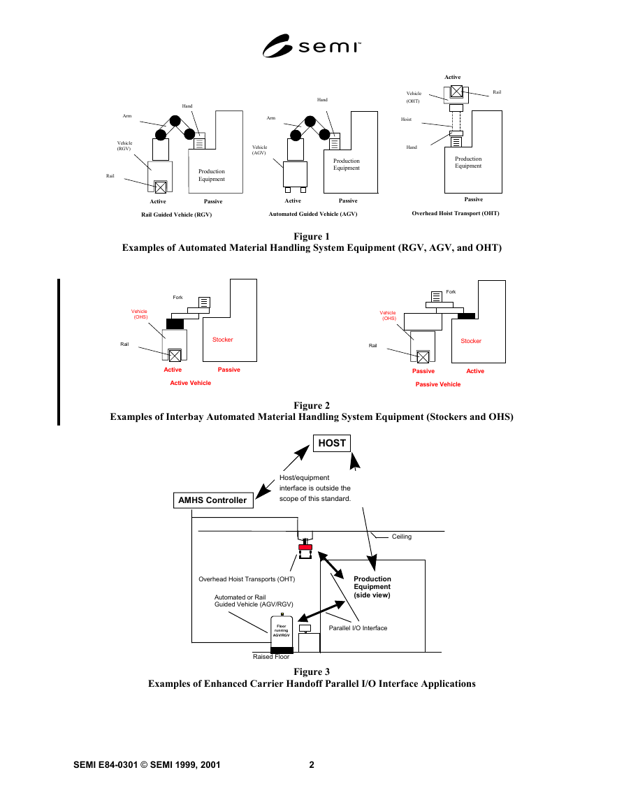
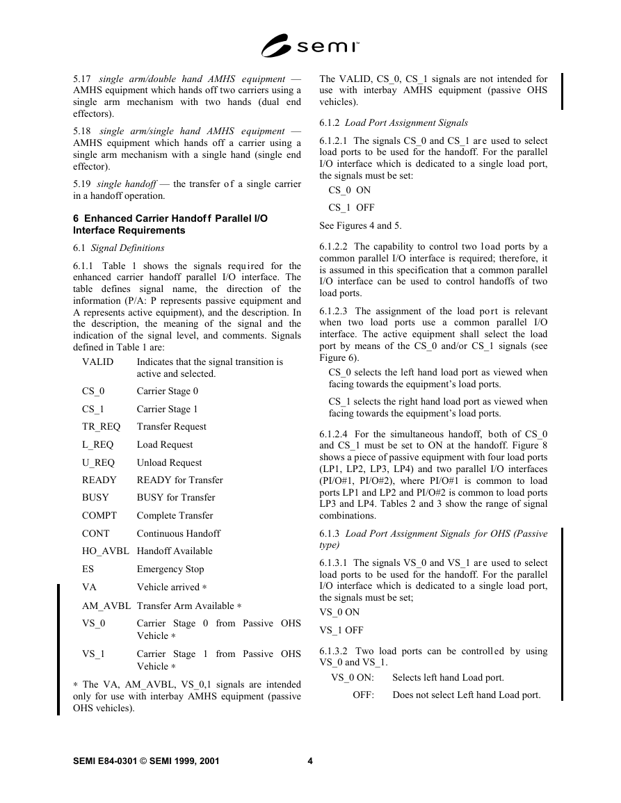
Figures 1 and 2 show examples of types of AMHS
equipment.
2.2 This enhanced carrier handoff parallel I/O
interface specification includes:
• Signal definition including load port assignment
signals (see Section 6.1),
• Carrier handoff sequence definitions and time
diagrams (see Section 6.2),
• Error indication, detection, and recovery (see
Sections 6.3 and 6.4),
• Connector type, signal, and pin assignment (see
Section 6.4), and
Interface sensor unit size to be located at load port
defined by SEMI E15.1 (applicable for systems
designed to handle 300 mm wafer carriers).
•
2.3 The enhanced carrier handoff parallel I/O interface
controls the handoff of a carrier to and from the passive
equipment by the active equipment. This parallel I/O
interface only controls the automated handoff operation
of the carrier. The handoff is the operation in which a
carrier is transferred from one piece of equipment to
another. Both the active and passive equipment manage
this operation. The factory level controller (i.e., host)
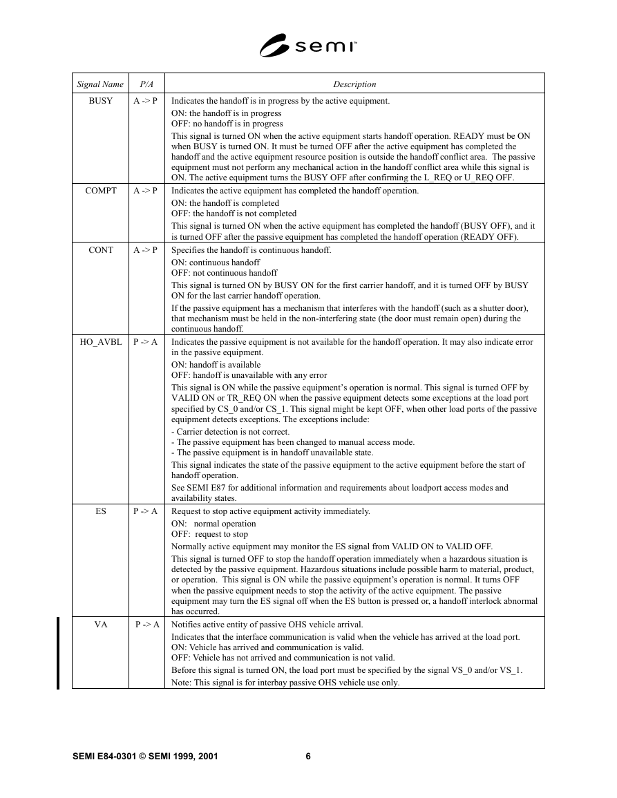
does not manage the handoff operation. Figure 3 shows
applications for the parallel I/O interface specified in
this document.
2.4 This standard does not purport to address safety
issues, if any, associated with its use. It is the
responsibility of the users of this standard to establish
appropriate safety and health practices and determine
the applicability of regulatory limitations prior to use.
3 Limitations
3.1 Data for the material that is transferred (handed
off) is managed through the equipment’s factory
interface. Material management by the factory level
controller is outside the scope of this document.
3.2 This specification defines the signals used to select
a load port. The physical correspondence of the parallel
I/O interface to the load port is not defined in this
document.
3.3 Error recovery procedures may need operator
assistance and/or proprietary procedures specific to the
equipment. Therefore, error recovery procedures are not
defined in this document.
3.4 Signal time diagrams apply to only one parallel
I/O interface.
1
SEMI E84-0301 © SEMI 1999, 2001
�
Arm
Vehicle
(RGV)
Rail
Hand
Hand
Arm
Vehicle
(AGV)
Production
Equipment
Production
Equipment
Active
Passive
Rail Guided Vehicle (RGV)
Active
Passive
Automated Guided Vehicle (AGV)
Active
Rail
Vehicle
(OHT)
Hoist
Hand
Production
Equipment
Passive
Overhead Hoist Transport (OHT)
Examples of Automated Material Handling System Equipment (RGV, AGV, and OHT)
Figure 1
Vehicle
(OHS)
Rail
Fork
Stocker
Active
Passive
Active Vehicle
Vehicle
(OHS)
Rail
Fork
Stocker
Passive
Passive Vehicle
Active
Examples of Interbay Automated Material Handling System Equipment (Stockers and OHS)
Figure 2
HOST
Host/equipment
interface is outside the
scope of this standard.
AMHS Controller
Ceiling
Production
Equipment
(side view)
Parallel I/O Interface
Overhead Hoist Transports (OHT)
Automated or Rail
Guided Vehicle (AGV/RGV)
Floor
running
AGV/RGV
Raised Floor
Examples of Enhanced Carrier Handoff Parallel I/O Interface Applications
Figure 3
SEMI E84-0301 © SEMI 1999, 2001
2
�
3.5 The installation positions of the parallel I/O
interface and the connector on the active and passive
equipment are not defined.
3.6 The swap handoff will be considered beyond the
scope of the standard for interbay AMHS equipment
(i.e., OHS, stockers). During a swap handoff, loading
and unloading occur simultaneously on the same
loadport.
4 Referenced Standards
4.1 SEMI Standards
SEMI E1.9 — Provisional Mechanical Specification for
Cassettes Used to Transport and Store 300 Wafers
SEMI E15.1 — Provisional Specification for 300 mm
Tool Load Port
SEMI E23 — Specification for Cassette Transfer
Parallel I/O Interface
SEMI E30 — Generic Model for Communications and
Control of SEMI Equipment (GEM)
SEMI E47.1 — Provisional Mechanical Specification
for Boxes and Pods Used to Transport and Store 300
mm Wafers
SEMI E87 — Provisional Specification for Carrier
Management (CMS)
4.2 ISO Standard 1
ISO 4902 —
communication — 37-pole DTE/DCE
connector and contact number assignments
NOTE 2: As listed or revised, all documents cited shall be the
latest publications of adopted standards.
technology — Data
interface
Information
5 Terminology
5.1 access mode — a mode in which passive
equipment knows which AMHS equipment (i.e. RGV,
AGV, and OHT/OHV) or operator is permitted to make
a material handoff.
5.2 active equipment — equipment that loads a
cassette onto the cassette stage of another piece of
equipment or unloads a cassette from the cassette stage
of another piece of equipment [SEMI E23].
5.3 automated material handling system (AMHS)
equipment — a piece of equipment which has a carrier
transfer robot that transfers carriers from and to passive
equipment. It includes rail guided vehicles (RGV),
automated guided vehicles (AGV), overhead hoist
transports (OHT), and stockers.
1 ISO Central Secretariat, 1, rue de Varembé, Case postale 56, CH-
1211 Genève 20, Switzerland
5.4 automatic access mode — a mode in which
AMHS equipment performs a material handoff rather
than an operator.
5.5 carrier — any cassette, box, pod, or FOUP that
contains wafers [SEMI E1.9]. Also known as wafer
carrier.
5.6 cassette — an open structure that holds one or
more substrates [SEMI E1.9]. Also known as open
cassette (OC).
5.7 continuous handoff — successive handoffs of two
carriers. Continuous handoff is in series, meaning one
carrier transfer occurs and is then immediately followed
by another. The continuous handoff may involve: load
and load, unload and unload, or unload and load
operations.
5.8 front opening unified pod (FOUP) — a box (that
complies with SEMI E47.1) with a non-removable
cassette (so that its interior complies with SEMI E1.9)
and with a front-opening interface (FIMS) [SEMI
E47.1].
5.9 handoff — is the operation in which a carrier is
transferred (loaded or unloaded) from one piece of
equipment to another.
5.10 handoff conflict area — an area where the active
equipment resource could interfere with the passive
equipment resource during the handoff operation.
5.11 handoff interlock abnormal — the state, which
indicates the passive equipment, has detected abnormal
conditions in the handoff operation. It may indicate the
possibility that the interference of the active equipment
resource with the passive equipment resource has
occurred in the handoff conflict area.
5.12 handoff unavailable — the state, which indicates
the passive equipment, is not available for material
handoff operation.
5.13 load port — the interface location on a tool
where wafer carriers are placed to allow the tool to
process wafers [SEMI E15].
5.14 manual access mode — an access mode in which
an operator performs a material handoff of a carrier
rather than the AMHS equipment.
5.15 passive equipment — equipment that is loaded or
unloaded by active equipment [SEMI E23]. Passive
equipment
includes process equipment, metrology
equipment, stockers, etc.
5.16 simultaneous handoff — concurrent handoff
operations of two carriers. Simultaneous handoff is in
parallel, meaning two carriers are transferred at the
same time.
3
SEMI E84-0301 © SEMI 1999, 2001
�
5.17 single arm/double hand AMHS equipment —
AMHS equipment which hands off two carriers using a
single arm mechanism with two hands (dual end
effectors).
5.18 single arm/single hand AMHS equipment —
AMHS equipment which hands off a carrier using a
single arm mechanism with a single hand (single end
effector).
5.19 single handoff — the transfer of a single carrier
in a handoff operation.
6 Enhanced Carrier Handof f Parallel I/O
Interface Requirements
6.1 Signal Definitions
6.1.1 Table 1 shows the signals required for the
enhanced carrier handoff parallel I/O interface. The
table defines signal name,
the
information (P/A: P represents passive equipment and
A represents active equipment), and the description. In
the description, the meaning of the signal and the
indication of the signal level, and comments. Signals
defined in Table 1 are:
the direction of
VALID
Indicates that the signal transition is
active and selected.
Carrier Stage 0
Carrier Stage 1
Transfer Request
Load Request
Unload Request
READY for Transfer
BUSY for Transfer
Complete Transfer
Continuous Handoff
CS_0
CS_1
TR_REQ
L_REQ
U_REQ
READY
BUSY
COMPT
CONT
HO_AVBL Handoff Available
ES
VA
AM_AVBL Transfer Arm Available ∗
VS_0
Emergency Stop
Vehicle arrived ∗
VS_1
Carrier Stage 0 from Passive OHS
Vehicle ∗
Carrier Stage 1 from Passive OHS
Vehicle ∗
∗ The VA, AM_AVBL, VS_0,1 signals are intended
only for use with interbay AMHS equipment (passive
OHS vehicles).
SEMI E84-0301 © SEMI 1999, 2001
4
The VALID, CS_0, CS_1 signals are not intended for
use with interbay AMHS equipment (passive OHS
vehicles).
6.1.2 Load Port Assignment Signals
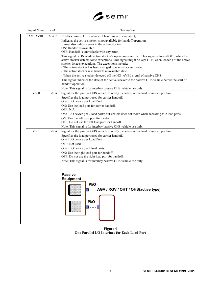
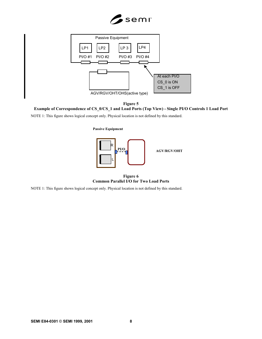
6.1.2.1 The signals CS_0 and CS_1 are used to select
load ports to be used for the handoff. For the parallel
I/O interface which is dedicated to a single load port,
the signals must be set:
CS_0 ON
CS_1 OFF
See Figures 4 and 5.
6.1.2.2 The capability to control two load ports by a
common parallel I/O interface is required; therefore, it
is assumed in this specification that a common parallel
I/O interface can be used to control handoffs of two
load ports.
6.1.2.3 The assignment of the load port is relevant
when two load ports use a common parallel I/O
interface. The active equipment shall select the load
port by means of the CS_0 and/or CS_1 signals (see
Figure 6).
CS_0 selects the left hand load port as viewed when
facing towards the equipment’s load ports.
CS_1 selects the right hand load port as viewed when
facing towards the equipment’s load ports.
6.1.2.4 For the simultaneous handoff, both of CS_0
and CS_1 must be set to ON at the handoff. Figure 8
shows a piece of passive equipment with four load ports
(LP1, LP2, LP3, LP4) and two parallel I/O interfaces
(PI/O#1, PI/O#2), where PI/O#1 is common to load
ports LP1 and LP2 and PI/O#2 is common to load ports
LP3 and LP4. Tables 2 and 3 show the range of signal
combinations.
6.1.3 Load Port Assignment Signals for OHS (Passive
type)
6.1.3.1 The signals VS_0 and VS_1 are used to select
load ports to be used for the handoff. For the parallel
I/O interface which is dedicated to a single load port,
the signals must be set;
VS_0 ON
VS_1 OFF
6.1.3.2 Two load ports can be controlled by using
VS_0 and VS_1.
VS_0 ON:
OFF:
Selects left hand Load port.
Does not select Left hand Load port.
�
VS_1 ON:
OFF:
Selects Right hand Load port.
Does not select Right hand Load port.
VS_0 and VS_1 are controlled individually.
Table 1 Signals for the Enhanced Carrier Handoff Parallel I/O Interface
Signal Name
VALID
P/A
A -> P
CS_0
A -> P
CS_1
A -> P
TR_REQ
A -> P
L_REQ
P -> A
U_REQ
P -> A
READY
P -> A
Description
Indicates that the interface communication is valid.
ON: the communication is valid
OFF: the communication is not valid
Before this signal is turned ON, the load port must be specified by the signal CS_0 and/or CS_1.
Specifies the load port used for carrier handoff (see Section 6.1.2, Load Port Assignment Signals).
One PI/O device per load port
ON: Use the load port for carrier handoff
OFF: N/A
One PI/O device per 2 load ports
ON: Use the left load port for handoff
OFF: Do not use the left load port of handoff
Specifies the load port used for carrier handoff (see Section 6.1.2, Load Port Assignment Signals).
One PI/O device per load port
Not used (OFF)
One PI/O device per 2 load ports
ON: Use the right load port for handoff
OFF: Do not use the right load port of handoff
Requests the handoff to the passive equipment.
ON: the active equipment has requested the handoff
OFF: the active equipment has not requested the handoff
This signal is turned OFF when the BUSY signal transitions to OFF.
Indicates the load port is assigned to load a carrier. L_REQ always indicates a carrier transfer from
Active to Passive equipment.
ON: The load port is assigned to load a carrier
OFF: The load port is not assigned to load a carrier
This signal is turned ON when the load port is specified by CS_0 and/or CS_1 and the VALID signal
is turned ON. This signal is turned OFF when the load port detects the carrier in the correct position.
In simultaneous handoff, the carrier on both load ports shall not be present when this signal is turned
ON, and the carriers shall be present in correct position on both load ports when this signal is turned
OFF.
Indicates the load port is assigned to unload a carrier. U_REQ always indicates a carrier transfer
from Passive to Active equipment.
ON: The load port is assigned to unload a carrier
OFF: The load port is not assigned to unload a carrier
This signal is turned ON when the load port is specified by CS_0 and/or CS_1, and the VALID
signal is turned ON. This signal is turned OFF when the carrier on the load port is removed.
In simultaneous handoff, the carrier on both load ports shall be present in correct position when this
signal is turned ON, and the carriers shall not be present on both load ports when this signal is turned
OFF.
Indicates the passive equipment has accepted the transfer request from the active equipment.
ON: the passive equipment is ready for the handoff
OFF: the passive equipment is not ready for the handoff
This signal is turned ON when the passive equipment accepts the transfer request, and it is turned
OFF when the COMPT signal is turned ON.
5
SEMI E84-0301 © SEMI 1999, 2001
�
Signal Name
BUSY
P/A
A -> P
COMPT
A -> P
CONT
A -> P
HO_AVBL
P -> A
ES
P -> A
Description
Indicates the handoff is in progress by the active equipment.
ON: the handoff is in progress
OFF: no handoff is in progress
This signal is turned ON when the active equipment starts handoff operation. READY must be ON
when BUSY is turned ON. It must be turned OFF after the active equipment has completed the
handoff and the active equipment resource position is outside the handoff conflict area. The passive
equipment must not perform any mechanical action in the handoff conflict area while this signal is
ON. The active equipment turns the BUSY OFF after confirming the L_REQ or U_REQ OFF.
Indicates the active equipment has completed the handoff operation.
ON: the handoff is completed
OFF: the handoff is not completed
This signal is turned ON when the active equipment has completed the handoff (BUSY OFF), and it
is turned OFF after the passive equipment has completed the handoff operation (READY OFF).
Specifies the handoff is continuous handoff.
ON: continuous handoff
OFF: not continuous handoff
This signal is turned ON by BUSY ON for the first carrier handoff, and it is turned OFF by BUSY
ON for the last carrier handoff operation.
If the passive equipment has a mechanism that interferes with the handoff (such as a shutter door),
that mechanism must be held in the non-interfering state (the door must remain open) during the
continuous handoff.
Indicates the passive equipment is not available for the handoff operation. It may also indicate error
in the passive equipment.
ON: handoff is available
OFF: handoff is unavailable with any error
This signal is ON while the passive equipment’s operation is normal. This signal is turned OFF by
VALID ON or TR_REQ ON when the passive equipment detects some exceptions at the load port
specified by CS_0 and/or CS_1. This signal might be kept OFF, when other load ports of the passive
equipment detects exceptions. The exceptions include:
- Carrier detection is not correct.
- The passive equipment has been changed to manual access mode.
- The passive equipment is in handoff unavailable state.
This signal indicates the state of the passive equipment to the active equipment before the start of
handoff operation.
See SEMI E87 for additional information and requirements about loadport access modes and
availability states.
Request to stop active equipment activity immediately.
ON: normal operation
OFF: request to stop
Normally active equipment may monitor the ES signal from VALID ON to VALID OFF.
This signal is turned OFF to stop the handoff operation immediately when a hazardous situation is
detected by the passive equipment. Hazardous situations include possible harm to material, product,
or operation. This signal is ON while the passive equipment’s operation is normal. It turns OFF
when the passive equipment needs to stop the activity of the active equipment. The passive
equipment may turn the ES signal off when the ES button is pressed or, a handoff interlock abnormal
has occurred.
VA
P -> A Notifies active entity of passive OHS vehicle arrival.
Indicates that the interface communication is valid when the vehicle has arrived at the load port.
ON: Vehicle has arrived and communication is valid.
OFF: Vehicle has not arrived and communication is not valid.
Before this signal is turned ON, the load port must be specified by the signal VS_0 and/or VS_1.
Note: This signal is for interbay passive OHS vehicle use only.
SEMI E84-0301 © SEMI 1999, 2001
6
�
Signal Name
AM_AVBL A -> P Notifies passive OHS vehicle of handling arm availability.
Description
P/A
Indicates the active stocker is not available for handoff operation.
It may also indicate error in the active stocker.
ON: Handoff is available.
OFF: Handoff is unavailable with any error.
This signal is ON while active stocker’s operation is normal. This signal is turned OFF, when the
active stocker detects some exceptions. This signal might be kept OFF, when loader’s of the active
stocker detects exceptions. The exceptions include:
- The active stocker has been changed to manual access mode.
- The active stocker is in handoff unavailable state.
- When the active stocker detected off the HO_AVBL signal of passive OHS.
This signal indicates the state of the active stocker to the passive OHS vehicle before the start of
handoff operation.
Note: This signal is for interbay passive OHS vehicle use only.
VS_0
P -> A Signal for the passive OHS vehicle to notify the active of the load or unload position.
Specifies the load port used for carrier handoff.
One PI/O device per Load Port.
ON: Use the load port for carrier handoff.
OFF: N/A
One PI/O device per 2 load ports; but vehicle does not move when accessing to 2 load ports.
ON: Use the left load port for handoff.
OFF: Do not use the left load port for handoff.
Note: This signal is for interbay passive OHS vehicle use only.
VS_1
P -> A Signal for the passive OHS vehicle to notify the active of the load or unload position.
Specifies the load port used for carrier handoff.
One PI/O device per Load Port.
OFF: Not used
One PI/O device per 2 load ports.
ON: Use the right load port for handoff.
OFF: Do not use the right load port for handoff.
Note: This signal is for interbay passive OHS vehicle use only.
Passive
Equipment
PI/O
PI/O
AGV / RGV / OHT / OHS(active type)
One Parallel I/O Interface for Each Load Port
Figure 4
7
SEMI E84-0301 © SEMI 1999, 2001
�
Passive Equipment
LP1
LP2
LP 3
LP4
PI/O #1 PI/O #2
PI/O #3 PI/O #4
At each PI/O
CS_0 is ON
CS_1 is OFF
AGV/RGV/OHT/OHS(active type)
Example of Correspondence of CS_0/CS_1 and Load Ports (Top View) - Single PI/O Controls 1 Load Port
Figure 5
NOTE 1: This figure shows logical concept only. Physical location is not defined by this standard.
Passive Equipment
PI/O
R
L
AGV/RGV/OHT
NOTE 1: This figure shows logical concept only. Physical location is not defined by this standard.
Common Parallel I/O for Two Load Ports
Figure 6
SEMI E84-0301 © SEMI 1999, 2001
8
�





 2023年江西萍乡中考道德与法治真题及答案.doc
 2012年重庆南川中考生物真题及答案.doc
 2013年江西师范大学地理学综合及文艺理论基础考研真题.doc
 2020年四川甘孜小升初语文真题及答案I卷.doc
 2020年注册岩土工程师专业基础考试真题及答案.doc
 2023-2024学年福建省厦门市九年级上学期数学月考试题及答案.doc
 2021-2022学年辽宁省沈阳市大东区九年级上学期语文期末试题及答案.doc
 2022-2023学年北京东城区初三第一学期物理期末试卷及答案.doc
 2018上半年江西教师资格初中地理学科知识与教学能力真题及答案.doc
 2012年河北国家公务员申论考试真题及答案-省级.doc
 2020-2021学年江苏省扬州市江都区邵樊片九年级上学期数学第一次质量检测试题及答案.doc
 2022下半年黑龙江教师资格证中学综合素质真题及答案.doc