Product Specification
IEEE 802.11 a/b/g/n/ac 2T2R SDIO Combo Module
IEEE 802.11 a/b/g/n/ac 2T2R SDIO Combo Module
IEEE 802.11 a/b/g/n/ac 2T2R SDIO Combo Module
With Bluetooth v2.1+EDR/Bluetooth 3.0/3.0+HS/4.1
With Bluetooth v2.1+EDR/Bluetooth 3.0/3.0+HS/4.1
With Bluetooth v2.1+EDR/Bluetooth 3.0/3.0+HS/4.1
Project Name
Realtek RTL8822BS Combo Module
BL-M8822BS1
Model NO
Customer
Customer’s Part NO
Approved:
Lingo.Wang
13510620050
Check:
CRUS.Zeng
Draft:
Mike.Liu
Feedback of customer’s Confirmation
We accept the specification after Confirmed.
Customer
Customer signature
Approved Date
Customer: Agenter :NATER TECH
Add: Add: 2F,NO.27,2 Baomin Rd.,Baoan Dist.SZ City,China
Tel: Tel:+86-755-85250145/13510620050
Fax: Fax:+86-755-61522172
Attn: Attn:Lingo
E-mail: E-mail:hsdgood@163.com
�
BL-M8822BS1
IEEE 802.11 a/b/g/n/ac 2T2R SDIO WIFI Module&BT 2.1/3.0/4.1
型号预览 Model Overview:
型号
安装方式
支持标准
速率
频段
天线接口
备注
BL-M8822BS1
SMD
IEEE802.11 a/b/g/n/ac
866.7Mbps
2.4G/5G
BT 2.1/3.0/4.1
24 Mbps
2.4G
外置天线 3.3V 供电
1. Introduction
BL-M8822BS1 module design is based on RTL8822BS-CG solution, The Realtek RTL8822BS-CG is a
highly integrated single-chip that support 2-stream 802.11ac solutions with Multi-user MIMO
(Multiple-Input, Multiple-Output) with integrated Bluetooth 2.1/3.0/4.1 controller,SDIO (SDIO 1.1/2.0/3.0)
interface, and HS-UART mixed interface. It combines a WLAN MAC, a 2T2R capable WLAN baseband,
and RF in s single chip. The RTL8822BS-CG provides a complete solution for a high-performance
integrated wireless and Bluetooth device.
1.1 RF module Overview
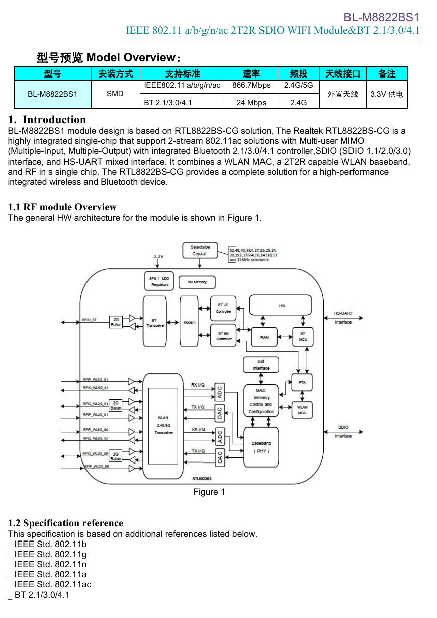
The general HW architecture for the module is shown in Figure 1.
Figure 1
Figure 1
1.2 Specification reference
This specification is based on additional references listed below.
_ IEEE Std. 802.11b
_ IEEE Std. 802.11g
_ IEEE Std. 802.11n
_ IEEE Std. 802.11a
_ IEEE Std. 802.11ac
_ BT 2.1/3.0/4.1
�
BL-M8822BS1
IEEE 802.11 a/b/g/n/ac 2T2R SDIO WIFI Module&BT 2.1/3.0/4.1
1.3 System Functions
Table1: General Specification as below:
RTL8822BS
2.4G/5G
802.11a/b/g/n/ac (2x2)
2.1/3.0/4.1
WIFI:11b: DBPSK, DQPSK and CCK and DSSS
11a/g: BPSK, QPSK, 16QAM, 64QAM and OFDM
11n: BPSK, QPSK, 16QAM, 64QAM and OFDM
11ac:BPSK, QPSK, 16QAM, 64QAM,256QAM and OFDM
BT:FSHH,GFSK,DPSK,DQPSK
11b: 1, 2, 5.5 and 11Mbps
11g: 6, 9, 12, 18, 24, 36, 48 and 54 Mbps
11n: MCS0~15, up to 300Mbps
11ac:MCS0~9,Nss=2,up to 866.7Mbps
BT2.0:up to 3Mbps
BT3.0/4.1:up to 24Mbps
50pins
SDIO/UART/PCM
4-layers design
Typical,13.0mmx 15.0mm x 2.0mm
External Antennas Design
0℃ to +60℃
-15℃ to +45℃
3.0V~3.6V
Main Chipset
Operating Frequency
WIFI Standard
Bluetooth
Modulation
Data rates
Form factor
Host Interface
PCB Stack
Dimension
Antenna
Operation Temperature
Storage Temperature
Operation Voltage
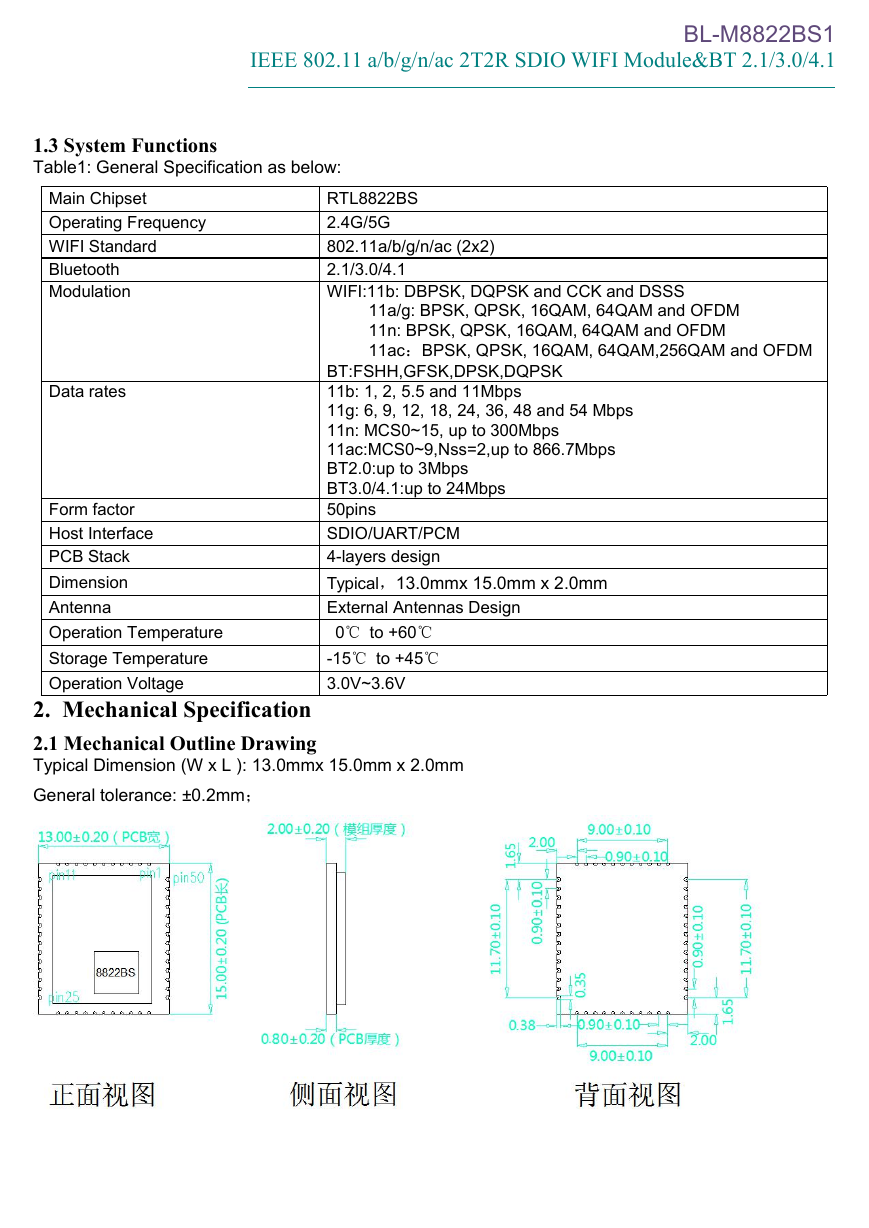
2. Mechanical Specification
2.1 Mechanical Outline Drawing
Typical Dimension (W x L ): 13.0mmx 15.0mm x 2.0mm
General tolerance: ±0.2mm;
�
BL-M8822BS1
IEEE 802.11 a/b/g/n/ac 2T2R SDIO WIFI Module&BT 2.1/3.0/4.1
Pin
26
27
Define
Not connect
PCM_SYNC
Not connect
PCM Synchronization
control, shared with GPIO2
PCM data Input, shared with
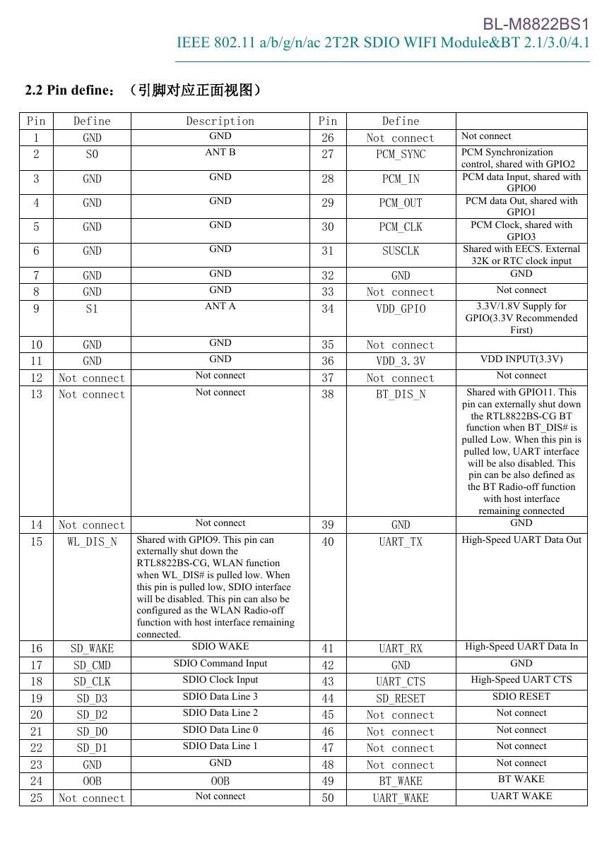
2.2 Pin define:(引脚对应正面视图)
Pin
1
2
3
4
5
6
7
8
9
10
11
12
13
Define
Description
GND
S0
GND
GND
GND
GND
GND
GND
S1
GND
GND
GND
ANT B
GND
GND
GND
GND
GND
GND
ANT A
GND
GND
Not connect
Not connect
Not connect
Not connect
14
15
Not connect
WL_DIS_N
16
17
18
19
20
21
22
23
24
25
SD_WAKE
SD_CMD
SD_CLK
SD_D3
SD_D2
SD_D0
SD_D1
GND
OOB
Not connect
Not connect
Shared with GPIO9. This pin can
externally shut down the
RTL8822BS-CG, WLAN function
when WL_DIS# is pulled low. When
this pin is pulled low, SDIO interface
will be disabled. This pin can also be
configured as the WLAN Radio-off
function with host interface remaining
connected.
SDIO WAKE
SDIO Command Input
SDIO Clock Input
SDIO Data Line 3
SDIO Data Line 2
SDIO Data Line 0
SDIO Data Line 1
GND
OOB
Not connect
28
29
30
31
32
33
34
35
36
37
38
39
40
41
42
43
44
45
46
47
48
49
50
PCM_IN
PCM_OUT
PCM_CLK
SUSCLK
GND
Not connect
VDD_GPIO
Not connect
VDD_3.3V
Not connect
BT_DIS_N
GND
UART_TX
PCM data Out, shared with
PCM Clock, shared with
GPIO0
GPIO1
GPIO3
Shared with EECS. External
32K or RTC clock input
GND
Not connect
3.3V/1.8V Supply for
GPIO(3.3V Recommended
First)
VDD INPUT(3.3V)
Not connect
Shared with GPIO11. This
pin can externally shut down
the RTL8822BS-CG BT
function when BT_DIS# is
pulled Low. When this pin is
pulled low, UART interface
will be also disabled. This
pin can be also defined as
the BT Radio-off function
with host interface
remaining connected
GND
High-Speed UART Data Out
UART_RX
GND
UART_CTS
SD_RESET
Not connect
Not connect
Not connect
Not connect
BT_WAKE
UART_WAKE
High-Speed UART Data In
GND
High-Speed UART CTS
SDIO RESET
Not connect
Not connect
Not connect
Not connect
BT WAKE
UART WAKE
�
BL-M8822BS1
IEEE 802.11 a/b/g/n/ac 2T2R SDIO WIFI Module&BT 2.1/3.0/4.1
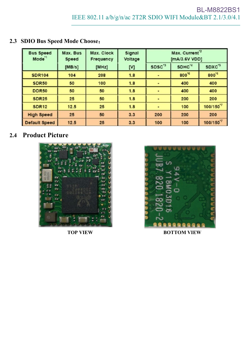
2.3 SDIO Bus Speed Mode Choose:
2.4 Product Picture
TOP VIEW
BOTTOM VIEW
�
BL-M8822BS1
IEEE 802.11 a/b/g/n/ac 2T2R SDIO WIFI Module&BT 2.1/3.0/4.1
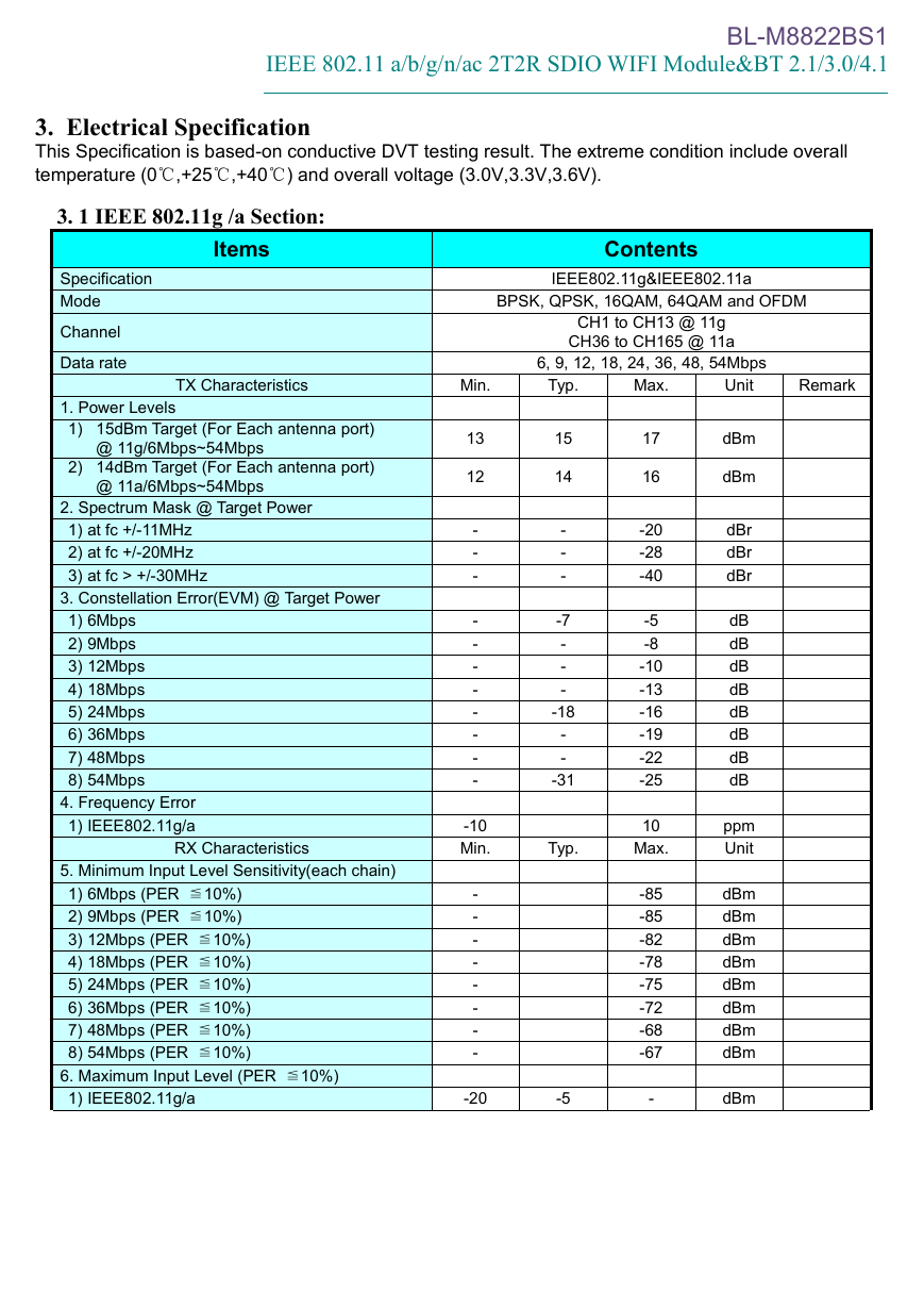
3. Electrical Specification
This Specification is based-on conductive DVT testing result. The extreme condition include overall
temperature (0℃,+25℃,+40℃) and overall voltage (3.0V,3.3V,3.6V).
3. 1 IEEE 802.11g /a Section:
Items
Specification
Mode
Channel
Data rate
Contents
IEEE802.11g&IEEE802.11a
BPSK, QPSK, 16QAM, 64QAM and OFDM
CH1 to CH13 @ 11g
CH36 to CH165 @ 11a
6, 9, 12, 18, 24, 36, 48, 54Mbps
TX Characteristics
Min.
Typ.
Max.
Unit
Remark
1. Power Levels
1) 15dBm Target (For Each antenna port)
@ 11g/6Mbps~54Mbps
2) 14dBm Target (For Each antenna port)
@ 11a/6Mbps~54Mbps
2. Spectrum Mask @ Target Power
1) at fc +/-11MHz
2) at fc +/-20MHz
3) at fc > +/-30MHz
3. Constellation Error(EVM) @ Target Power
1) 6Mbps
2) 9Mbps
3) 12Mbps
4) 18Mbps
5) 24Mbps
6) 36Mbps
7) 48Mbps
8) 54Mbps
4. Frequency Error
1) IEEE802.11g/a
RX Characteristics
5. Minimum Input Level Sensitivity(each chain)
1) 6Mbps (PER ≦10%)
2) 9Mbps (PER ≦10%)
3) 12Mbps (PER ≦10%)
4) 18Mbps (PER ≦10%)
5) 24Mbps (PER ≦10%)
6) 36Mbps (PER ≦10%)
7) 48Mbps (PER ≦10%)
8) 54Mbps (PER ≦10%)
6. Maximum Input Level (PER ≦10%)
1) IEEE802.11g/a
13
12
-
-
-
-
-
-
-
-
-
-
-
15
14
-
-
-
-7
-
-
-
-18
-
-
-31
17
16
-20
-28
-40
-5
-8
-10
-13
-16
-19
-22
-25
-10
Min.
Typ.
10
Max.
-
-
-
-
-
-
-
-
-20
-5
-85
-85
-82
-78
-75
-72
-68
-67
-
dBm
dBm
dBr
dBr
dBr
dB
dB
dB
dB
dB
dB
dB
dB
ppm
Unit
dBm
dBm
dBm
dBm
dBm
dBm
dBm
dBm
dBm
�
BL-M8822BS1
IEEE 802.11 a/b/g/n/ac 2T2R SDIO WIFI Module&BT 2.1/3.0/4.1
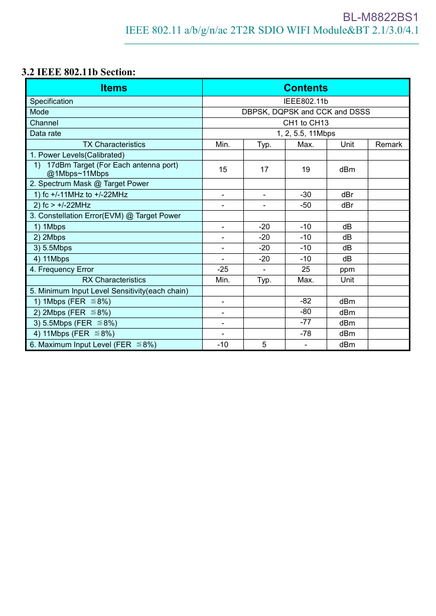
3.2 IEEE 802.11b Section:
Items
Specification
Mode
Channel
Data rate
Contents
IEEE802.11b
DBPSK, DQPSK and CCK and DSSS
CH1 to CH13
1, 2, 5.5, 11Mbps
TX Characteristics
Min.
Typ.
Max.
Unit
Remark
1. Power Levels(Calibrated)
1) 17dBm Target (For Each antenna port)
@1Mbps~11Mbps
2. Spectrum Mask @ Target Power
1) fc +/-11MHz to +/-22MHz
2) fc > +/-22MHz
3. Constellation Error(EVM) @ Target Power
1) 1Mbps
2) 2Mbps
3) 5.5Mbps
4) 11Mbps
4. Frequency Error
RX Characteristics
5. Minimum Input Level Sensitivity(each chain)
1) 1Mbps (FER ≦8%)
2) 2Mbps (FER ≦8%)
3) 5.5Mbps (FER ≦8%)
4) 11Mbps (FER ≦8%)
6. Maximum Input Level (FER ≦8%)
15
-
-
-
-
-
-
-25
Min.
-
-
-
-
-10
17
-
-
-20
-20
-20
-20
-
Typ.
5
19
-30
-50
-10
-10
-10
-10
25
Max.
-82
-80
-77
-78
-
dBm
dBr
dBr
dB
dB
dB
dB
ppm
Unit
dBm
dBm
dBm
dBm
dBm
�
BL-M8822BS1
IEEE 802.11 a/b/g/n/ac 2T2R SDIO WIFI Module&BT 2.1/3.0/4.1
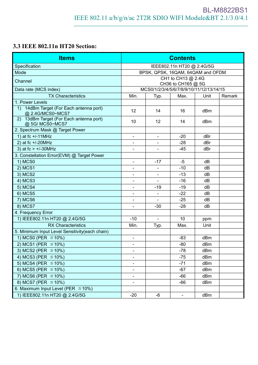
3.3 IEEE 802.11n HT20 Section:
Items
Specification
Mode
Channel
Data rate (MCS index)
Contents
IEEE802.11n HT20 @ 2.4G/5G
BPSK, QPSK, 16QAM, 64QAM and OFDM
CH1 to CH13 @ 2.4G
CH36 to CH165 @ 5G
MCS0/1/2/3/4/5/6/7/8/9/10/11/12/13/14/15
TX Characteristics
Min.
Typ.
Max.
Unit
Remark
1. Power Levels
1) 14dBm Target (For Each antenna port)
@ 2.4G/MCS0~MCS7
2) 13dBm Target (For Each antenna port)
@ 5G/ MCS0~MCS7
2. Spectrum Mask @ Target Power
1) at fc +/-11MHz
2) at fc +/-20MHz
3) at fc > +/-30MHz
3. Constellation Error(EVM) @ Target Power
1) MCS0
2) MCS1
3) MCS2
4) MCS3
5) MCS4
6) MCS5
7) MCS6
8) MCS7
4. Frequency Error
1) IEEE802.11n HT20 @ 2.4G/5G
RX Characteristics
5. Minimum Input Level Sensitivity(each chain)
1) MCS0 (PER ≦10%)
2) MCS1 (PER ≦10%)
3) MCS2 (PER ≦10%)
4) MCS3 (PER ≦10%)
5) MCS4 (PER ≦10%)
6) MCS5 (PER ≦10%)
7) MCS6 (PER ≦10%)
8) MCS7 (PER ≦10%)
6. Maximum Input Level (PER ≦10%)
1) IEEE802.11n HT20 @ 2.4G/5G
12
10
-
-
-
-
-
-
-
-
-
-
-
14
12
-
-
-
-17
-
-
-
-19
-
-
-30
16
14
-20
-28
-45
-5
-10
-13
-16
-19
-22
-25
-28
-10
Min.
-
Typ.
10
Max.
-
-
-
-
-
-
-
-
-20
-6
-83
-80
-78
-75
-71
-67
-66
-66
-
dBm
dBm
dBr
dBr
dBr
dB
dB
dB
dB
dB
dB
dB
dB
ppm
Unit
dBm
dBm
dBm
dBm
dBm
dBm
dBm
dBm
dBm
�



 2023年江西萍乡中考道德与法治真题及答案.doc
 2012年重庆南川中考生物真题及答案.doc
 2013年江西师范大学地理学综合及文艺理论基础考研真题.doc
 2020年四川甘孜小升初语文真题及答案I卷.doc
 2020年注册岩土工程师专业基础考试真题及答案.doc
 2023-2024学年福建省厦门市九年级上学期数学月考试题及答案.doc
 2021-2022学年辽宁省沈阳市大东区九年级上学期语文期末试题及答案.doc
 2022-2023学年北京东城区初三第一学期物理期末试卷及答案.doc
 2018上半年江西教师资格初中地理学科知识与教学能力真题及答案.doc
 2012年河北国家公务员申论考试真题及答案-省级.doc
 2020-2021学年江苏省扬州市江都区邵樊片九年级上学期数学第一次质量检测试题及答案.doc
 2022下半年黑龙江教师资格证中学综合素质真题及答案.doc