logo资料库

disperse软件的用户手册.pdf

第1页 / 共207页
第2页 / 共207页
第3页 / 共207页
第4页 / 共207页
第5页 / 共207页
第6页 / 共207页
第7页 / 共207页
第8页 / 共207页
资料共207页,剩余部分请下载后查看
1 Introduction
1.1 What Disperse Can Model
1.2 Limitations
1.3 What Else Disperse Can Do
1.4 Installing and running Disperse
1.5 Display Logic and Mouse Actions
1.6 New Features for Version 2.0
1.7 Warnings
2 Getting Started Quickly
2.1 Quick Start - Flat Isotropic Free Plate
2.2 Quick Start - Flat Isotropic Plate in Water
3 Defining the Structure
3.1 Getting Started
3.2 Defining the Geometry
3.2.1 Some Simple Examples
3.3 Defining a Layer
3.3.1 Liquid
3.3.2 Isotropic
3.3.3 Anisotropic
3.3.4 Variation of properties with frequency
3.3.5 Interface
3.3.6 Boundary
3.4 Opening an Existing File
4 Tracing the Dispersion Curves
4.1 Overview
4.2 Automatic Tracing of Dispersion Curves
4.3 Manually Tracing Dispersion Curves
4.3.1 Sweeping
4.3.2 Tracing
4.3.3 Converging on Roots
4.4 Special Solution Options
4.4.1 Types of Solution
4.4.2 Material Property Variation
5 Displaying the Dispersion Curves
5.1 The Basics
5.2 Default two-dimensional Display Types
5.2.1 Phase Velocity
5.2.2 Group Velocity
5.2.3 Attenuation
5.2.4 Real Wave Number
5.3 Other Forms of Display
5.3.1 Second Graph
5.3.2 Select Axes
5.3.3 Hide Curves
5.3.4 Derived Data
5.3.5 Sweep Results
5.4 Using the Display
5.4.1 Zooming and Moving
5.4.2 Using the Pointer in the Display Window
5.4.3 Toolbar and Edit Options
5.5 Preferences
6 Tools for Processing the Results
6.1 Mode Shapes
6.1.1 Lines
6.1.2 Grid
6.1.3 Power
6.2 Simulated signal
6.2.1 Excitation
6.2.2 Multi-mode
6.3 Calculate function
6.3.1 Input Using Menu Options
6.3.2 Input Using General Equation
6.3.3 Sampling Information
6.4 Show Bulk Velocities
6.5 Verify Solution
6.6 Resample Data
6.7 Input and Output of Information
6.7.1 Saving
6.7.2 Exporting
6.7.3 Import Text File
6.7.4 Copy and Paste
6.7.5 Printing
6.8 Labels
7 Wave Propagation Model
7.1 Wave Equations in Bulk Isotropic Media - General Theory
7.1.1 Properties of the Wave Equation with Attenuation
7.1.2 Treatment for Fluid Materials
7.2 Wave Propagation in Isotropic Flat Plate Structures
7.2.1 Historical Background
7.2.2 Plane Waves in an Infinite Elastic Solid
7.2.3 Plane waves in a Two-Dimensional Space
7.2.4 The Superposition of Plane Waves in a Layered Plate
7.3 Cylindrical Wave Propagation in Isotropic Materials
7.3.1 Historical Background of Cylindrical Wave Propagation
7.3.2 Assumptions and Limitations
7.3.3 Boundary Conditions
7.3.4 Waves in Finite Layers
7.4 Cartesian Wave Propagation in Orthotropic Media
7.4.1 Bulk Waves in Anisotropic Media
7.4.2 Lamb-Type Modes
7.4.3 Shear Horizontal Modes
7.4.4 The Layer Matrix
7.5 Global Matrix Method
7.6 Spring Interface
7.7 Analytical Solutions for Leaky Lamb Case
7.8 Finding a Root
7.9 Tracing a Dispersion Curve
7.10 Mode Shapes
8 Cartesian Examples
8.1 Lamb Waves
8.1.1 Tracing the Curves
8.1.2 Interpreting the Results
8.2 Leaky Lamb Waves
8.3 Surface and Interface Waves
8.3.1 True Rayleigh Waves
8.3.2 Leaky Rayleigh Waves
8.3.3 Stoneley Waves
8.3.4 Thin Layer on a Half-Space
8.4 Visco-Elastic Layers
8.5 Multi-Layered Structures
8.6 Embedded Layers
8.7 Anisotropic Layers
9 Cylindrical Examples
9.1 Cylinders in Vacuum
9.1.1 Tracing the Dispersion Curves
9.1.2 Projections
9.1.3 Naming
9.1.4 Nature of the Modes in Solid Cylinders
9.1.5 Nature of the Modes in Hollow Cylinders
9.1.6 Effect of Changing the Radius
9.2 Cylinders Immersed in a Fluid
9.2.1 Modelling the Fluid Inside the Cylinder
9.2.2 Leakage into the Surrounding Medium
9.3 Cylinders Embedded in a Solid
9.3.1 Different Types of Leakage
9.3.2 Multi-layered, Visco-elastic, Pipes, Embedded in a Solid
10 Additional Information
10.1 File Structure
10.2 How to Get in Contact
10.3 This User Manual
A Summary of Useful Relations
A.1 Relations between Lambda, Rho and Mu
A.2 Wave Speeds
A.3 Constitutive and Compatibility Relations for Elastic Isotropic Material
A.4 Relations between Velocity and Attenuation Constants for Isotropic Materials
A.5 Engineering and Cij Constants for Orthotropic Materials
A.6 Attenuation of waves in materials with complex Cij constants
A.7 Bessel Function Recurrence Relations
A.8 Operations in Cylindrical Coordinates
B List of Examples
C Common Material Properties
D Bibliography
E Index
DISPERSEUser'sManualMichaelLoweandBrianPavlakovicAsystemforGeneratingDispersionCurvesVersion2.0.20aJuly2013Non-DestructiveTestingLaboratoryDepartmentofMechanicalEngineeringImperialCollegeLondonLondon,SW72AZUKEmail:m.lowe@imperial.ac.ukWeb:www.imperial.ac.uk/ndeCopyrightMLowe,BPavlakovic(c)2013
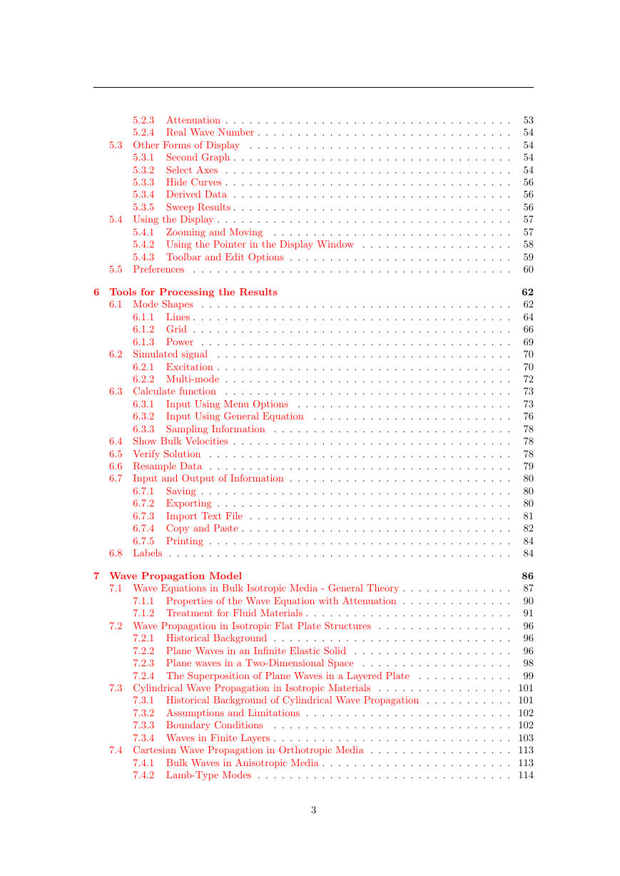
Contents 1 Introduction 1.1 What Disperse Can Model . . . . . . . . . . . . . . . . . . . . . . . . . . . . . . . . 1.2 Limitations . . . . . . . . . . . . . . . . . . . . . . . . . . . . . . . . . . . . . . . . 1.3 What Else Disperse Can Do . . . . . . . . . . . . . . . . . . . . . . . . . . . . . . . 1.4 Installing and running Disperse . . . . . . . . . . . . . . . . . . . . . . . . . . . . . 1.5 Display Logic and Mouse Actions . . . . . . . . . . . . . . . . . . . . . . . . . . . . 1.6 New Features for Version 2.0 . . . . . . . . . . . . . . . . . . . . . . . . . . . . . . . . . . . . . . . . . . . . . . . . . . . . . . . . . . . . . . . . . . . . . . . 1.7 Warnings 2 Getting Started Quickly 2.1 Quick Start - Flat Isotropic Free Plate . . . . . . . . . . . . . . . . . . . . . . . . . 2.2 Quick Start - Flat Isotropic Plate in Water . . . . . . . . . . . . . . . . . . . . . . 3 Defining the Structure 3.2.1 Some Simple Examples 3.3 Defining a Layer 3.1 Getting Started . . . . . . . . . . . . . . . . . . . . . . . . . . . . . . . . . . . . . . 3.2 Defining the Geometry . . . . . . . . . . . . . . . . . . . . . . . . . . . . . . . . . . . . . . . . . . . . . . . . . . . . . . . . . . . . . . . . . . . . . . . . . . . . . . . . . . . . . . . . . . . . . . . . . . . . 3.3.1 Liquid . . . . . . . . . . . . . . . . . . . . . . . . . . . . . . . . . . . . . . . 3.3.2 Isotropic . . . . . . . . . . . . . . . . . . . . . . . . . . . . . . . . . . . . . . 3.3.3 Anisotropic . . . . . . . . . . . . . . . . . . . . . . . . . . . . . . . . . . . . 3.3.4 Variation of properties with frequency . . . . . . . . . . . . . . . . . . . . . 3.3.5 Interface . . . . . . . . . . . . . . . . . . . . . . . . . . . . . . . . . . . . . . 3.3.6 Boundary . . . . . . . . . . . . . . . . . . . . . . . . . . . . . . . . . . . . . . . . . . . . . . . . . . . . . . . . . . . . . . . . . . . . . 3.4 Opening an Existing File 4 Tracing the Dispersion Curves 4.1 Overview . . . . . . . . . . . . . . . . . . . . . . . . . . . . . . . . . . . . . . . . . 4.2 Automatic Tracing of Dispersion Curves . . . . . . . . . . . . . . . . . . . . . . . . 4.3 Manually Tracing Dispersion Curves . . . . . . . . . . . . . . . . . . . . . . . . . . 4.3.1 Sweeping . . . . . . . . . . . . . . . . . . . . . . . . . . . . . . . . . . . . . 4.3.2 Tracing . . . . . . . . . . . . . . . . . . . . . . . . . . . . . . . . . . . . . . 4.3.3 Converging on Roots . . . . . . . . . . . . . . . . . . . . . . . . . . . . . . . 4.4 Special Solution Options . . . . . . . . . . . . . . . . . . . . . . . . . . . . . . . . . 4.4.1 Types of Solution . . . . . . . . . . . . . . . . . . . . . . . . . . . . . . . . . 4.4.2 Material Property Variation . . . . . . . . . . . . . . . . . . . . . . . . . . . 5 Displaying the Dispersion Curves 5.1 The Basics 5.2 Default two-dimensional Display Types . . . . . . . . . . . . . . . . . . . . . . . . . . . . . . . . . . . . . . . . . . . . . . . . . . . . . . . . . . . . . . . . 5.2.1 Phase Velocity . . . . . . . . . . . . . . . . . . . . . . . . . . . . . . . . . . 5.2.2 Group Velocity . . . . . . . . . . . . . . . . . . . . . . . . . . . . . . . . . . 2 10 10 11 11 12 13 14 15 16 17 18 20 20 20 23 23 24 25 26 33 34 35 35 36 36 37 39 40 41 42 46 46 48 51 51 52 52 52
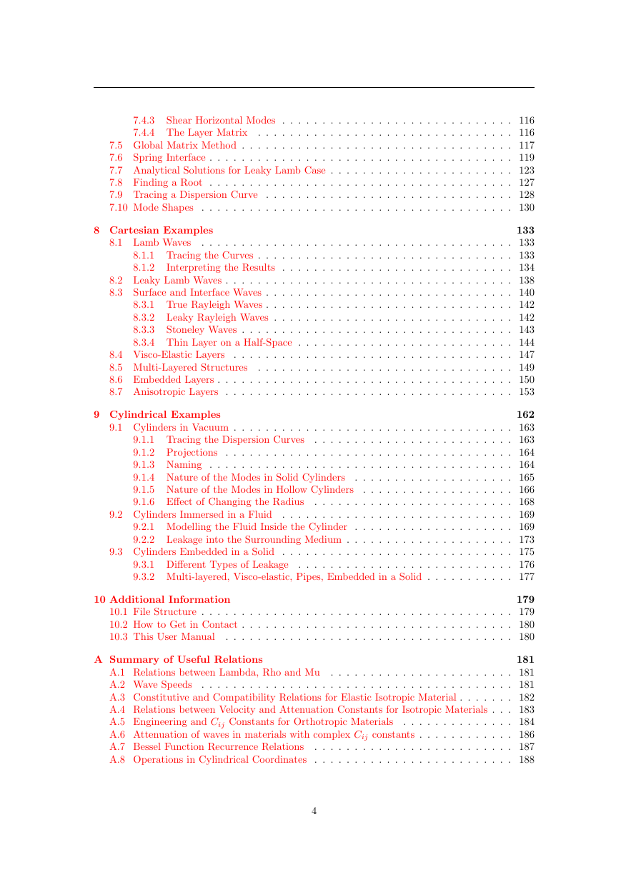
5.2.3 Attenuation . . . . . . . . . . . . . . . . . . . . . . . . . . . . . . . . . . . . 5.2.4 Real Wave Number . . . . . . . . . . . . . . . . . . . . . . . . . . . . . . . . 5.3 Other Forms of Display . . . . . . . . . . . . . . . . . . . . . . . . . . . . . . . . . Second Graph . . . . . . . . . . . . . . . . . . . . . . . . . . . . . . . . . . . 5.3.1 5.3.2 Select Axes . . . . . . . . . . . . . . . . . . . . . . . . . . . . . . . . . . . . 5.3.3 Hide Curves . . . . . . . . . . . . . . . . . . . . . . . . . . . . . . . . . . . . 5.3.4 Derived Data . . . . . . . . . . . . . . . . . . . . . . . . . . . . . . . . . . . 5.3.5 Sweep Results . . . . . . . . . . . . . . . . . . . . . . . . . . . . . . . . . . . 5.4 Using the Display . . . . . . . . . . . . . . . . . . . . . . . . . . . . . . . . . . . . . 5.4.1 Zooming and Moving . . . . . . . . . . . . . . . . . . . . . . . . . . . . . . 5.4.2 Using the Pointer in the Display Window . . . . . . . . . . . . . . . . . . . 5.4.3 Toolbar and Edit Options . . . . . . . . . . . . . . . . . . . . . . . . . . . . . . . . . . . . . . . . . . . . . . . . . . . . . . . . . . . . . . . . . . . . 5.5 Preferences 6 Tools for Processing the Results 6.3.1 6.3.2 6.3.3 6.2 Simulated signal 6.1 Mode Shapes . . . . . . . . . . . . . . . . . . . . . . . . . . . . . . . . . . . . . . . 6.1.1 Lines . . . . . . . . . . . . . . . . . . . . . . . . . . . . . . . . . . . . . . . . 6.1.2 Grid . . . . . . . . . . . . . . . . . . . . . . . . . . . . . . . . . . . . . . . . 6.1.3 Power . . . . . . . . . . . . . . . . . . . . . . . . . . . . . . . . . . . . . . . . . . . . . . . . . . . . . . . . . . . . . . . . . . . . . . . . . . . . 6.2.1 Excitation . . . . . . . . . . . . . . . . . . . . . . . . . . . . . . . . . . . . . 6.2.2 Multi-mode . . . . . . . . . . . . . . . . . . . . . . . . . . . . . . . . . . . . 6.3 Calculate function . . . . . . . . . . . . . . . . . . . . . . . . . . . . . . . . . . . . Input Using Menu Options . . . . . . . . . . . . . . . . . . . . . . . . . . . Input Using General Equation . . . . . . . . . . . . . . . . . . . . . . . . . Sampling Information . . . . . . . . . . . . . . . . . . . . . . . . . . . . . . 6.4 Show Bulk Velocities . . . . . . . . . . . . . . . . . . . . . . . . . . . . . . . . . . . 6.5 Verify Solution . . . . . . . . . . . . . . . . . . . . . . . . . . . . . . . . . . . . . . 6.6 Resample Data . . . . . . . . . . . . . . . . . . . . . . . . . . . . . . . . . . . . . . Input and Output of Information . . . . . . . . . . . . . . . . . . . . . . . . . . . . 6.7 6.7.1 Saving . . . . . . . . . . . . . . . . . . . . . . . . . . . . . . . . . . . . . . . 6.7.2 Exporting . . . . . . . . . . . . . . . . . . . . . . . . . . . . . . . . . . . . . 6.7.3 Import Text File . . . . . . . . . . . . . . . . . . . . . . . . . . . . . . . . . 6.7.4 Copy and Paste . . . . . . . . . . . . . . . . . . . . . . . . . . . . . . . . . . 6.7.5 Printing . . . . . . . . . . . . . . . . . . . . . . . . . . . . . . . . . . . . . . 6.8 Labels . . . . . . . . . . . . . . . . . . . . . . . . . . . . . . . . . . . . . . . . . . . 53 54 54 54 54 56 56 56 57 57 58 59 60 62 62 64 66 69 70 70 72 73 73 76 78 78 78 79 80 80 80 81 82 84 84 7 Wave Propagation Model 7.1 Wave Equations in Bulk Isotropic Media - General Theory . . . . . . . . . . . . . . 7.1.1 Properties of the Wave Equation with Attenuation . . . . . . . . . . . . . . 7.1.2 Treatment for Fluid Materials . . . . . . . . . . . . . . . . . . . . . . . . . . 7.2 Wave Propagation in Isotropic Flat Plate Structures . . . . . . . . . . . . . . . . . 7.2.1 Historical Background . . . . . . . . . . . . . . . . . . . . . . . . . . . . . . 7.2.2 Plane Waves in an Infinite Elastic Solid . . . . . . . . . . . . . . . . . . . . 7.2.3 Plane waves in a Two-Dimensional Space . . . . . . . . . . . . . . . . . . . 7.2.4 The Superposition of Plane Waves in a Layered Plate . . . . . . . . . . . . 86 87 90 91 96 96 96 98 99 7.3 Cylindrical Wave Propagation in Isotropic Materials . . . . . . . . . . . . . . . . . 101 7.3.1 Historical Background of Cylindrical Wave Propagation . . . . . . . . . . . 101 7.3.2 Assumptions and Limitations . . . . . . . . . . . . . . . . . . . . . . . . . . 102 7.3.3 Boundary Conditions . . . . . . . . . . . . . . . . . . . . . . . . . . . . . . 102 7.3.4 Waves in Finite Layers . . . . . . . . . . . . . . . . . . . . . . . . . . . . . . 103 7.4 Cartesian Wave Propagation in Orthotropic Media . . . . . . . . . . . . . . . . . . 113 7.4.1 Bulk Waves in Anisotropic Media . . . . . . . . . . . . . . . . . . . . . . . . 113 7.4.2 Lamb-Type Modes . . . . . . . . . . . . . . . . . . . . . . . . . . . . . . . . 114 3
7.4.3 Shear Horizontal Modes . . . . . . . . . . . . . . . . . . . . . . . . . . . . . 116 7.4.4 The Layer Matrix . . . . . . . . . . . . . . . . . . . . . . . . . . . . . . . . 116 7.5 Global Matrix Method . . . . . . . . . . . . . . . . . . . . . . . . . . . . . . . . . . 117 7.6 Spring Interface . . . . . . . . . . . . . . . . . . . . . . . . . . . . . . . . . . . . . . 119 7.7 Analytical Solutions for Leaky Lamb Case . . . . . . . . . . . . . . . . . . . . . . . 123 7.8 Finding a Root . . . . . . . . . . . . . . . . . . . . . . . . . . . . . . . . . . . . . . 127 7.9 Tracing a Dispersion Curve . . . . . . . . . . . . . . . . . . . . . . . . . . . . . . . 128 7.10 Mode Shapes . . . . . . . . . . . . . . . . . . . . . . . . . . . . . . . . . . . . . . . 130 8 Cartesian Examples 8.1 Lamb Waves 133 . . . . . . . . . . . . . . . . . . . . . . . . . . . . . . . . . . . . . . . 133 8.1.1 Tracing the Curves . . . . . . . . . . . . . . . . . . . . . . . . . . . . . . . . 133 8.1.2 Interpreting the Results . . . . . . . . . . . . . . . . . . . . . . . . . . . . . 134 8.2 Leaky Lamb Waves . . . . . . . . . . . . . . . . . . . . . . . . . . . . . . . . . . . . 138 8.3 Surface and Interface Waves . . . . . . . . . . . . . . . . . . . . . . . . . . . . . . . 140 8.3.1 True Rayleigh Waves . . . . . . . . . . . . . . . . . . . . . . . . . . . . . . . 142 8.3.2 Leaky Rayleigh Waves . . . . . . . . . . . . . . . . . . . . . . . . . . . . . . 142 8.3.3 Stoneley Waves . . . . . . . . . . . . . . . . . . . . . . . . . . . . . . . . . . 143 8.3.4 Thin Layer on a Half-Space . . . . . . . . . . . . . . . . . . . . . . . . . . . 144 . . . . . . . . . . . . . . . . . . . . . . . . . . . . . . . . . . . 147 8.4 Visco-Elastic Layers 8.5 Multi-Layered Structures . . . . . . . . . . . . . . . . . . . . . . . . . . . . . . . . 149 8.6 Embedded Layers . . . . . . . . . . . . . . . . . . . . . . . . . . . . . . . . . . . . . 150 8.7 Anisotropic Layers . . . . . . . . . . . . . . . . . . . . . . . . . . . . . . . . . . . . 153 9 Cylindrical Examples 162 9.1 Cylinders in Vacuum . . . . . . . . . . . . . . . . . . . . . . . . . . . . . . . . . . . 163 9.1.1 Tracing the Dispersion Curves . . . . . . . . . . . . . . . . . . . . . . . . . 163 9.1.2 Projections . . . . . . . . . . . . . . . . . . . . . . . . . . . . . . . . . . . . 164 9.1.3 Naming . . . . . . . . . . . . . . . . . . . . . . . . . . . . . . . . . . . . . . 164 . . . . . . . . . . . . . . . . . . . . 165 9.1.4 Nature of the Modes in Solid Cylinders . . . . . . . . . . . . . . . . . . . 166 9.1.5 Nature of the Modes in Hollow Cylinders 9.1.6 Effect of Changing the Radius . . . . . . . . . . . . . . . . . . . . . . . . . 168 9.2 Cylinders Immersed in a Fluid . . . . . . . . . . . . . . . . . . . . . . . . . . . . . 169 9.2.1 Modelling the Fluid Inside the Cylinder . . . . . . . . . . . . . . . . . . . . 169 9.2.2 Leakage into the Surrounding Medium . . . . . . . . . . . . . . . . . . . . . 173 9.3 Cylinders Embedded in a Solid . . . . . . . . . . . . . . . . . . . . . . . . . . . . . 175 9.3.1 Different Types of Leakage . . . . . . . . . . . . . . . . . . . . . . . . . . . 176 9.3.2 Multi-layered, Visco-elastic, Pipes, Embedded in a Solid . . . . . . . . . . . 177 10 Additional Information 179 10.1 File Structure . . . . . . . . . . . . . . . . . . . . . . . . . . . . . . . . . . . . . . . 179 10.2 How to Get in Contact . . . . . . . . . . . . . . . . . . . . . . . . . . . . . . . . . . 180 10.3 This User Manual . . . . . . . . . . . . . . . . . . . . . . . . . . . . . . . . . . . . 180 A Summary of Useful Relations 181 A.1 Relations between Lambda, Rho and Mu . . . . . . . . . . . . . . . . . . . . . . . 181 A.2 Wave Speeds . . . . . . . . . . . . . . . . . . . . . . . . . . . . . . . . . . . . . . . 181 A.3 Constitutive and Compatibility Relations for Elastic Isotropic Material . . . . . . . 182 A.4 Relations between Velocity and Attenuation Constants for Isotropic Materials . . . 183 A.5 Engineering and Cij Constants for Orthotropic Materials . . . . . . . . . . . . . . 184 A.6 Attenuation of waves in materials with complex Cij constants . . . . . . . . . . . . 186 A.7 Bessel Function Recurrence Relations . . . . . . . . . . . . . . . . . . . . . . . . . 187 A.8 Operations in Cylindrical Coordinates . . . . . . . . . . . . . . . . . . . . . . . . . 188 4
B List of Examples C Common Material Properties D Bibliography E Index 189 191 194 200 5
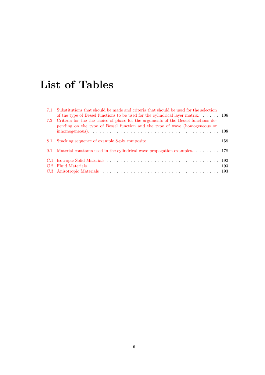
List of Tables 7.1 Substitutions that should be made and criteria that should be used for the selection of the type of Bessel functions to be used for the cylindrical layer matrix. . . . . . 106 7.2 Criteria for the the choice of phase for the arguments of the Bessel functions de- pending on the type of Bessel function and the type of wave (homogeneous or inhomogeneous). . . . . . . . . . . . . . . . . . . . . . . . . . . . . . . . . . . . . . 108 8.1 Stacking sequence of example 8-ply composite. . . . . . . . . . . . . . . . . . . . . 158 9.1 Material constants used in the cylindrical wave propagation examples. . . . . . . . 178 C.1 Isotropic Solid Materials . . . . . . . . . . . . . . . . . . . . . . . . . . . . . . . . . 192 C.2 Fluid Materials . . . . . . . . . . . . . . . . . . . . . . . . . . . . . . . . . . . . . . 193 C.3 Anisotropic Materials . . . . . . . . . . . . . . . . . . . . . . . . . . . . . . . . . . 193 6
List of Figures the fibres. 3.1 A Bond transformation matrix is used to rotate an anisotropic material. The orien- tation is specified by a rotation about the ˆx axis, followed by a rotation about the ˆy axis and a second rotation about the ˆx axis. The angles are specified in degrees. 3.2 A fibrous material is typically defined in the literature with the X axis parallel to . . . . . . . . . . . . . . . . . . . . . . . . . . . . . . . . . . . . . . . . . 3.3 View of how Disperse sees the example material after the constants have been entered using “Trans.Isotropic (Cij’s - along x)” but before any rotation angles have been specified. . . . . . . . . . . . . . . . . . . . . . . . . . . . . . . . . . . . 3.4 View of the example material after the constants have been entered and a theta . . . . . . . . . . . . . . . . . . . . . . . . 3.5 View of the defined material after a theta rotation of 90 degrees followed by a psi . . . . . . . . . . . . . . . . . . . . . . . . . . . . . . . . . . rotation of 90 degrees has been applied. rotation of 45 degrees. 27 31 32 32 33 7.1 Sample geometry of a five layer flat plate system showing the partial waves in each layer (L+-, SV+-, and SH+-) that combine to produce a guided wave. The SH+- partial waves are omitted in the case of Lamb waves in an isotropic plate, leaving just 4 partial waves in each layer. The L+- and SV+- partial waves are omitted in the case of Love waves in an isotropic plate, leaving just two partial waves in each layer. . . . . . . . . . . . . . . . . . . . . . . . . . . . . . . . . . . . . . . . . . . . . 7.2 Sample geometry of a five layer cylindrical system showing the partial waves in each . . . . . . . 7.3 The structure of the global matrix for a (a) solid, (b) liquid, and (c) vacuum half- space, where blank spaces are zeros, Dij is the layer matrix, and L+-, SV+-, and SH+- are the partial waves amplitudes in the various layers. . . . . . . . . . . . . . 119 layer (L+-, SV+-, and SH+-) that combine to produce a guided wave. 88 87 7.4 The process of finding a root involves a coarse sweep (thick line) to find an initial minimum and a fine search (dashed lines) to narrow down on a root (solid circle). The example above shows the absolute value of the determinant of the global matrix for a 1 mm steel plate immersed in water at a wave number of 4 rad/mm. . . . . . 128 7.5 Using an extrapolating routine to trace modes dramatically improves the program’s speed and reliability. . . . . . . . . . . . . . . . . . . . . . . . . . . . . . . . . . . . 129 8.1 8.2 (a) Phase velocity and (b) group velocity dispersion curves for a typical Lamb wave problem, a 1 mm thick steel plate in vacuum . . . . . . . . . . . . . . . . . . . . . 136 (a) Wave number and (b) angle of incidence dispersion curves for a typical Lamb wave problem, a 1 mm steel plate in vacuum . . . . . . . . . . . . . . . . . . . . . 137 8.3 Mode shapes for the two fundamental Lamb wave modes overlaid on the phase velocity dispersion curves. . . . . . . . . . . . . . . . . . . . . . . . . . . . . . . . . 138 8.4 Phase velocity dispersion curves for the “SH” modes for a 1 mm thick steel plate 8.5 in vacuum . . . . . . . . . . . . . . . . . . . . . . . . . . . . . . . . . . . . . . . . . 139 (a) Phase velocity and (b) attenuation dispersion curves for a typical leaky Lamb wave problem, a 1 mm steel plate in water . . . . . . . . . . . . . . . . . . . . . . . 141 7
8.6 The mode shape of a Rayleigh wave propagating on the surface of an aluminum half- space, shown (a) as a deformed grid and (b) as lines representing the displacement profiles. . . . . . . . . . . . . . . . . . . . . . . . . . . . . . . . . . . . . . . . . . . 143 8.7 The mode shape of a leaky Rayleigh wave propagating on the surface of an aluminum half-space which is water loaded, shown (a) as a deformed grid and (b) as lines representing the displacement profiles. . . . . . . . . . . . . . . . . . . . . . . . . . 144 8.8 The (a) in-plane and (b) normal displacement components of a Stoneley wave prop- agating at the interface of aluminum and steel half-spaces. The vertical axis cor- responds to the direction perpendicular to the interface and shows a depth of ap- proximately 5 wavelengths of the Stoneley wave. . . . . . . . . . . . . . . . . . . . 145 8.9 Phase velocity dispersion curves for a 0.1 mm thick epoxy layer on an aluminium half space. . . . . . . . . . . . . . . . . . . . . . . . . . . . . . . . . . . . . . . . . . 146 8.10 Phase velocity dispersion curve for the fundamental mode of a 0.1 mm thick epoxy layer on an aluminium half space. . . . . . . . . . . . . . . . . . . . . . . . . . . . . 146 8.11 The grid mode shapes for the fundamental mode of a 0.1 mm thick epoxy layer on an aluminium half space at (a) 2.0 MHz and (b) 8.0 MHz, showing the change in behaviour from a mode that is dominated by the properties of the aluminium properties to one that is dominated by those of the epoxy. . . . . . . . . . . . . . . 147 8.12 The (a) phase velocity and (b) attenuation dispersion curves for a layer of high performance polyethylene. . . . . . . . . . . . . . . . . . . . . . . . . . . . . . . . . 148 8.13 The phase velocity dispersion curves for a aluminum-epoxy-aluminum adhesive joint when the epoxy is 0.1 mm thick and has a stiffness of 4 GPa and the plates are 1 mm thick. . . . . . . . . . . . . . . . . . . . . . . . . . . . . . . . . . . . . . . . . . 150 8.14 The (a) phase velocity and (b) attenuation dispersion curves for a aluminum-epoxy- aluminum adhesive joint in water. The plates are 1 mm thick and the epoxy is 0.1 mm thick. . . . . . . . . . . . . . . . . . . . . . . . . . . . . . . . . . . . . . . . . . 151 8.15 The phase velocity dispersion curves for the example aluminum-epoxy-aluminum adhesive joint, when the epoxy has been artificially weakened by (a) lowering the stiffness to 3 GPa and (b) lowering the stiffness to 1 GPa and reducing the density by half. . . . . . . . . . . . . . . . . . . . . . . . . . . . . . . . . . . . . . . . . . . 151 8.16 The (a) phase velocity and (b) attenuation dispersion curves for an epoxy layer embedded in aluminum half-spaces. . . . . . . . . . . . . . . . . . . . . . . . . . . . 153 8.17 The (a) phase velocity and (b) group velocity dispersion curves for modes propa- gating parallel to the fibre direction in a unidirectional composite laminate. . . . . 155 8.18 (a) Displacement and (b) stress mode shapes for S0 mode parallel to fibres in unidirectional composite at 1 MHz. . . . . . . . . . . . . . . . . . . . . . . . . . . . 156 8.19 The (a) phase velocity and (b) group velocity dispersion curves for modes propa- gating at 45 degrees to the fibre direction in a unidirectional composite laminate. . 157 8.20 (a) Displacement and (b) stress mode shapes for S0 mode at 45 degrees to fibres in unidirectional composite at 1 MHz. . . . . . . . . . . . . . . . . . . . . . . . . . . . 157 8.21 Phase velocity curves for propagation in an 8 ply quasi-isotropic laminate, (a) in the direction of the fibres in layers 3 and 6 and (b) at 45 to that in (a). . . . . . . 159 8.22 Displacement and stress mode shapes for the (a) S0 mode and (b) A0 mode at 1 MHz in the example 8-ply quasi-isotropic composite plate. . . . . . . . . . . . . . . 160 8.23 (a) Displacement and (b) stress mode shapes for S0 mode propagating at 0 degrees in an 8-ply 0/90 composite at 1 MHz-mm. . . . . . . . . . . . . . . . . . . . . . . . 161 9.1 Various views of the dispersion curves for a 2 mm diameter steel bar in water: (a) real wave number, (b) phase velocity, (c) group velocity, and (d) angle of incidence. 165 9.2 Phase velocity dispersion curves for a 2 mm diameter steel steel bar with mode shapes super-imposed on the (a) fundamental modes and (b) higher order modes. . 167 9.3 Phase velocity and group velocity dispersion curves for an empty 1 mm thick steel pipe with an inner radius of 2 mm. . . . . . . . . . . . . . . . . . . . . . . . . . . . 168 8
分享到:
收藏