Chapter13
Design Example
Cell Name
XOR2X1, XNOR2X1
TIELO, TIEHI
OAI22X1, OAI21X1
NOR3X1, NOR2X2, NOR2X1
NAND3X1, NAND2X2, NAND2X1
MUX2X2, MUX2NX1
LCX1, LCNX1
INVX1, INVX2, INVX4, INVX8, INVX16
FILL8, FILL4, FILL2, FILL
ENINVX1, ENINVX2
DCX1, DCNX1, DCBX1, DCBNX1
BUFX8, BUFX4, BUFX2
AOI22X1, AOI21X1
AND3X1
Description
2-input XOR and XNOR
Cells used to tie inputs to logic 1 or 0
OR-AND-Invert gates with 4 (22) and 3 (21) inputs
2- and 3-input NOR
2- and 3-input NAND
2-input MUX, and 2-input inverting mux (N)
Gated latches
Inverters
Filler cells of various widths
These are used to fill empty spots in standard cell rows
Enabled inverters (tri-state inverters)
Edge triggered flip-flops
non-inverting buffers
AND-OR-Invert gates with 4 (22) and 3 (21) inputs
3-input AND
Figure 13.1: Cells contained in the UofU Digital v1 2 cell library. The cell names are coded
with output drive strengths: X1 is unit drive strength, and Xn is n-times that unit drive
strength. Sequential cells are coded with a C if they have a clear signal, B if they have
both Q and Qbar outputs, and N if they are clocked on a negative edge or level.
�
260
CHAPTER 13: Design Example
#/* -*- c -*- */
#/**********************************************************************/
#/* Defaults can be found in $SYNOPSYS/admin/setup/.synopsys_dc.setup */
#/**********************************************************************/
set company {University of Utah}
set designer {Erik Brunvand}
#/**********************************************************************/
set plot_command {lpr -Pcsps}
set text_print_command {lpr -Pcsps}
set text_editor_command {emacs %s &}
set command_log_file "./synopsys-dc_shell.log"
set view_command_log_file "./synopsys-dc_shell-view.log"
set find_converts_name_lists "false"
#/**********************************************************************/
set SynopsysInstall [getenv "SYNOPSYS"]
# You can add to this search path if you have your libraries
# stored somewhere else...
set search_path [list . \
[format "%s%s"
$SynopsysInstall /libraries/syn] \
[format "%s%s"
$SynopsysInstall /dw/sim_ver] ]
#/* ================================================= */
#/* Define a work library in the current project dir
*/
#/* to hold temporary files and keep the project area */
#/* uncluttered. Note: You must create a subdirectory */
#/* in your project directory called WORK.
*/
#/* ================================================= */
define_design_lib WORK -path ./WORK
#/* ================================================= */
#/* General configuration settings.
*/
#/* ================================================= */
set hdlin_check_no_latch true
set compile_fix_multiple_port_nets true
set hdlin_translate_off_skip_text true
set verilogout_write_components true
set verilogout_architecture_name "structural"
set verilogout_no_tri true
set hdlin_translate_off_skip_text true
set bus_naming_style {%s[%d]}
set target_library [list UofU_Digital_v1_2.db]
set synthetic_library [list dw_foundation.sldb]
set synlib_wait_for_design_license [list "DesignWare-Foundation"]
set link_library [concat
\
[concat
"*" $target_library] $synthetic_library]
set symbol_library [list generic.sdb]
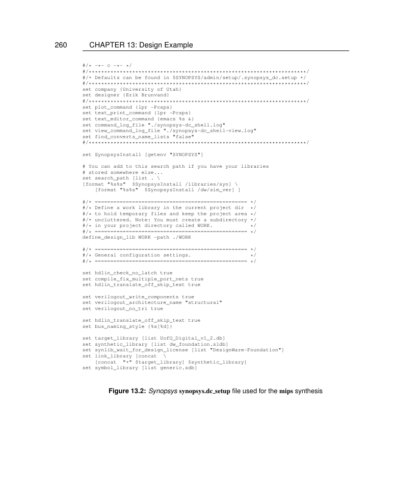
Figure 13.2: Synopsys synopsys.dc setup file used for the mips synthesis
�
261
################################################
# Synopsys Design Compiler synthesis script
# Erik Brunvand, Univeristy of Utah
################################################
#
# Target library list should include all target .db files
set target_library [list UofU_Digital_v1_2.db]
# Synthetic library is DesignWare from Synopsys which has
# details of arithmetic functions (among other things)
set synthetic_library [list dw_foundation.sldb]
set synlib_wait_for_design_license [list "DesignWare-Foundation"]
# Link library is a list of libraries to link the design against
set link_library [concat
"*" $target_library]
$synthetic_library]
[concat
# Generic symbols from Synopsys
set symbol_library [list generic.sdb]
# below are parameters that you will want to set for each design
# list of all HDL files in the design
set myFiles [list mips.v] ;# All the mips Verilog in one file
set fileFormat verilog
set basename mips
set myClk clk
set virtual 0
;# verilog or VHDL
;# Top-level module name
;# The name of your clock
;# 1 if virtual clock, 0 if real clock
# compiler switches...
set useUltra 1
;# 1 for compile_ultra, 0 for compile
# Timing and loading information
set myPeriod_ns 5
set myInDelay_ns 0.25
set myOutDelay_ns 0.25
set myInputBuf INVX4
set myLoadLibrary UofU_Digital_v1_2 ;# name of lib the cell is from
set myLoadPin A
;# desired clock period (sets speed goal)
;# delay from clock to inputs valid
;# delay from clock to output valid
;# name of cell driving the inputs
;# name of pin that outputs drive
# Control the writing of result files
set runname struct
;# Name appended to output files
# the following control which output files you want. They
# should be set to 1 if you want the file, 0 if not
set write_v 1
set write_ddc 1
set write_sdf 0
set write_sdc 1
set write_rep 1
set write_pow 0
;# compiled structural Verilog file
;# compiled file in ddc format (XG-mode)
;# sdf file for back-annotated timing sim
;# sdc constraint file for place and route
;# report file from compilation
;# report file for power estimate
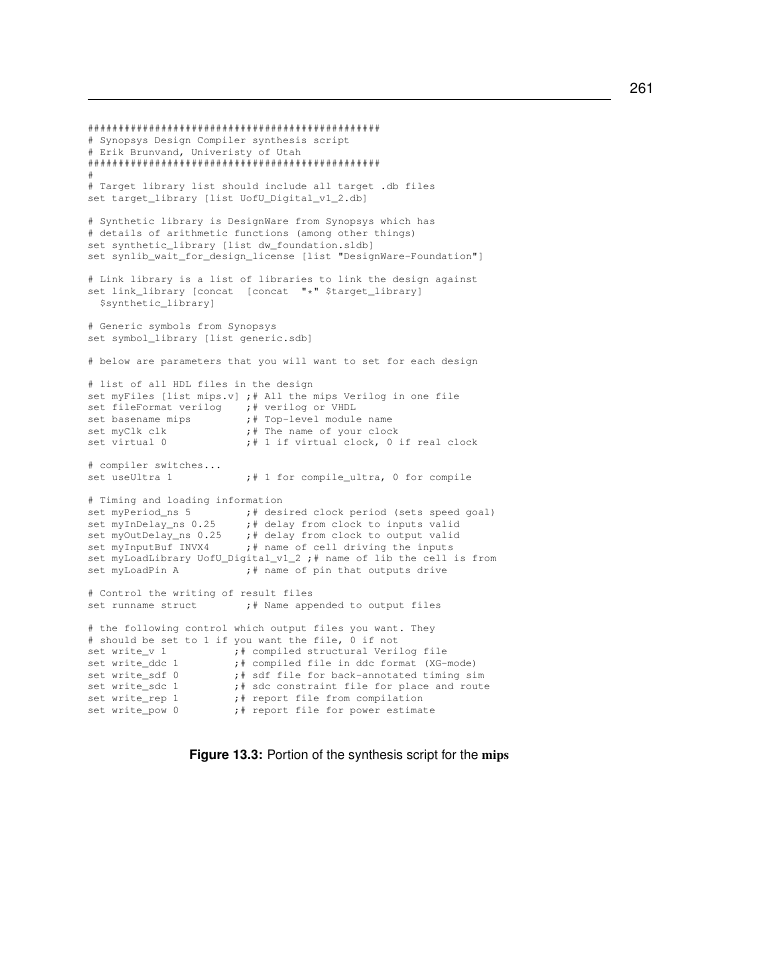
Figure 13.3: Portion of the synthesis script for the mips
�
262
CHAPTER 13: Design Example
module mips ( clk, reset, memdata, memread, memwrite, adr, writedata);
input [7:0] memdata;
output [7:0] adr;
output [7:0] writedata;
input clk, reset;
output memread, memwrite;
wire
dp_aluout_2_,
cont_N17, cont_N16, cont_state_0_, cont_state_1_,
dp_aluout_3_, dp_aluout_4_, dp_aluout_5_, dp_aluout_6_,
dp_aluout_7_,
dp_aluresult_2_, dp_aluresult_3_, dp_aluresult_7_, dp_pc_2_,
dp_pc_4_,
dp_pc_5_, dp_pc_6_, dp_pc_7_, dp_rf_N114, dp_rf_N110,
dp_rf_N109,
dp_rf_N108, dp_rf_N107, dp_rf_N104, dp_rf_N103, dp_rf_N102,
dp_rf_N101, dp_rf_N100, dp_rf_N99, dp_rf_N98, dp_rf_N97,
dp_rf_RAM_0__0_, dp_rf_RAM_0__1_, dp_rf_RAM_0__2_,
dp_rf_RAM_0__3_,
dp_rf_RAM_0__4_, dp_rf_RAM_0__5_, dp_rf_RAM_0__6_,
... 1302 lines deleted ...
MUX2X2 U1179 ( .A(memdata[4]), .B(instr[12]), .S(n845), .Y(n494) );
MUX2X2 U1180 ( .A(memdata[3]), .B(instr[11]), .S(n845), .Y(n496) );
MUX2NX1 U1181 ( .A(n703), .B(n150), .S(n838), .Y(n498) );
MUX2NX1 U1182 ( .A(n152), .B(n153), .S(n838), .Y(n500) );
MUX2NX1 U1183 ( .A(n154), .B(n959), .S(n838), .Y(n502) );
MUX2NX1 U1184 ( .A(n156), .B(n157), .S(n838), .Y(n504) );
MUX2NX1 U1185 ( .A(n158), .B(n159), .S(n838), .Y(n506) );
MUX2NX1 U1186 ( .A(n160), .B(n960), .S(n838), .Y(n508) );
MUX2NX1 U1187 ( .A(n160), .B(n1020), .S(n958), .Y(n510) );
MUX2NX1 U1188 ( .A(n158), .B(n1021), .S(n958), .Y(n512) );
MUX2NX1 U1189 ( .A(n156), .B(n953), .S(n958), .Y(n514) );
MUX2NX1 U1190 ( .A(n167), .B(n1022), .S(n958), .Y(n516) );
MUX2NX1 U1191 ( .A(n169), .B(n1023), .S(n958), .Y(n518) );
MUX2NX1 U1192 ( .A(n154), .B(n824), .S(n958), .Y(n520) );
MUX2NX1 U1193 ( .A(n152), .B(n1024), .S(n958), .Y(n522) );
MUX2NX1 U1194 ( .A(n703), .B(n1025), .S(n958), .Y(n524) );
AOI21X1 U1195 ( .A(instr[29]), .B(instr[31]), .C(n1027), .Y(n1029) );
AOI22X1 U1196 ( .A(n702), .B(n1037), .C(n1036), .D(n1035), .Y(n1038) );
endmodule
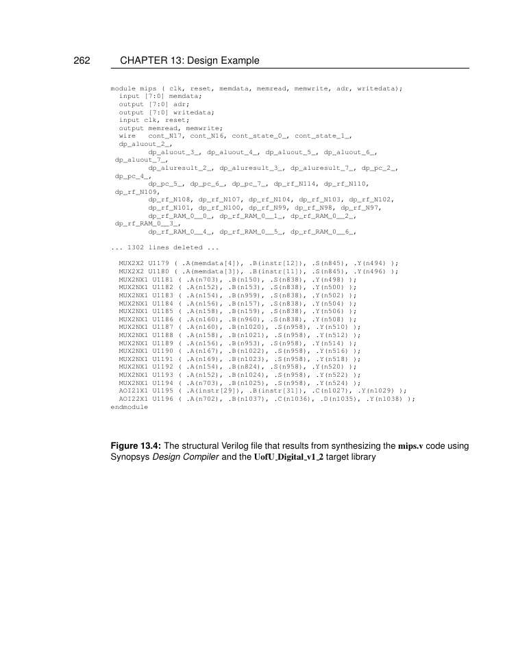
Figure 13.4: The structural Verilog file that results from synthesizing the mips.v code using
Synopsys Design Compiler and the UofU Digital v1 2 target library
�
263
###################################################################
# Created by write_sdc on Sun Sep 28 15:38:44 2008
###################################################################
set sdc_version 1.7
set_units -time ns -resistance kOhm -capacitance pF -voltage V -current uA
set_driving_cell -lib_cell INVX4 -library UofU_Digital_v1_2 [get_ports clk]
set_driving_cell -lib_cell INVX4 -library UofU_Digital_v1_2 [get_ports reset]
set_driving_cell -lib_cell INVX4 -library UofU_Digital_v1_2 [get_ports {memdata[7]}]
set_driving_cell -lib_cell INVX4 -library UofU_Digital_v1_2 [get_ports {memdata[6]}]
set_driving_cell -lib_cell INVX4 -library UofU_Digital_v1_2 [get_ports {memdata[5]}]
set_driving_cell -lib_cell INVX4 -library UofU_Digital_v1_2 [get_ports {memdata[4]}]
set_driving_cell -lib_cell INVX4 -library UofU_Digital_v1_2 [get_ports {memdata[3]}]
set_driving_cell -lib_cell INVX4 -library UofU_Digital_v1_2 [get_ports {memdata[2]}]
set_driving_cell -lib_cell INVX4 -library UofU_Digital_v1_2 [get_ports {memdata[1]}]
set_driving_cell -lib_cell INVX4 -library UofU_Digital_v1_2 [get_ports {memdata[0]}]
set_load -pin_load 0.0659726 [get_ports memread]
set_load -pin_load 0.0659726 [get_ports memwrite]
set_load -pin_load 0.0659726 [get_ports {adr[7]}]
... 29 Lines deleted ...
set_output_delay -clock clk
set_output_delay -clock clk
set_output_delay -clock clk
set_output_delay -clock clk
set_output_delay -clock clk
set_output_delay -clock clk
set_output_delay -clock clk
set_output_delay -clock clk
set_output_delay -clock clk
set_output_delay -clock clk
set_output_delay -clock clk
set_output_delay -clock clk
set_output_delay -clock clk
0.25
0.25
0.25
0.25
0.25
0.25
0.25
0.25
0.25
0.25
0.25
0.25
0.25
[get_ports {adr[4]}]
[get_ports {adr[3]}]
[get_ports {adr[2]}]
[get_ports {adr[1]}]
[get_ports {adr[0]}]
[get_ports {writedata[7]}]
[get_ports {writedata[6]}]
[get_ports {writedata[5]}]
[get_ports {writedata[4]}]
[get_ports {writedata[3]}]
[get_ports {writedata[2]}]
[get_ports {writedata[1]}]
[get_ports {writedata[0]}]
Figure 13.5: Timing file that results from synthesis of the mips.v code. This information is
used by the place and route process.
�
264
CHAPTER 13: Design Example
****************************************
Report : timing
-path full
-delay max
-max_paths 1
Design : mips
Version: Z-2007.03-SP4
Date
****************************************
: Sun Sep 28 15:38:44 2008
Operating Conditions: typical
Wire Load Model Mode: top
Library: UofU_Digital_v1_2
Startpoint: cont_state_reg_2_
(rising edge-triggered flip-flop clocked by clk)
Endpoint: dp_pcreg_q_reg_1_
(rising edge-triggered flip-flop clocked by clk)
Path Group: clk
Path Type: max
Point
--------------------------------------------------------------------------
clock clk (rise edge)
clock network delay (ideal)
cont_state_reg_2_/CLK (DCBX1)
cont_state_reg_2_/QB (DCBX1)
U843/Y (NOR2X1)
U606/Y (NAND2X2)
U611/Y (NAND3X1)
U876/Y (NOR2X2)
U785/Y (AOI22X1)
U787/Y (NAND2X1)
0.00
0.00
0.00 r
0.61 r
1.34 f
1.80 r
2.08 f
2.30 r
2.47 f
2.73 r
Path
Incr
0.00
0.00
0.00
0.61
0.73
0.46
0.28
0.22
0.17
0.26
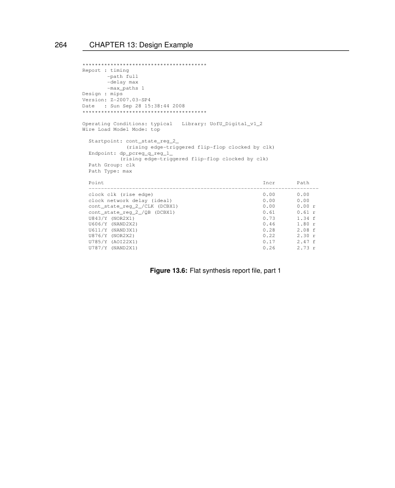
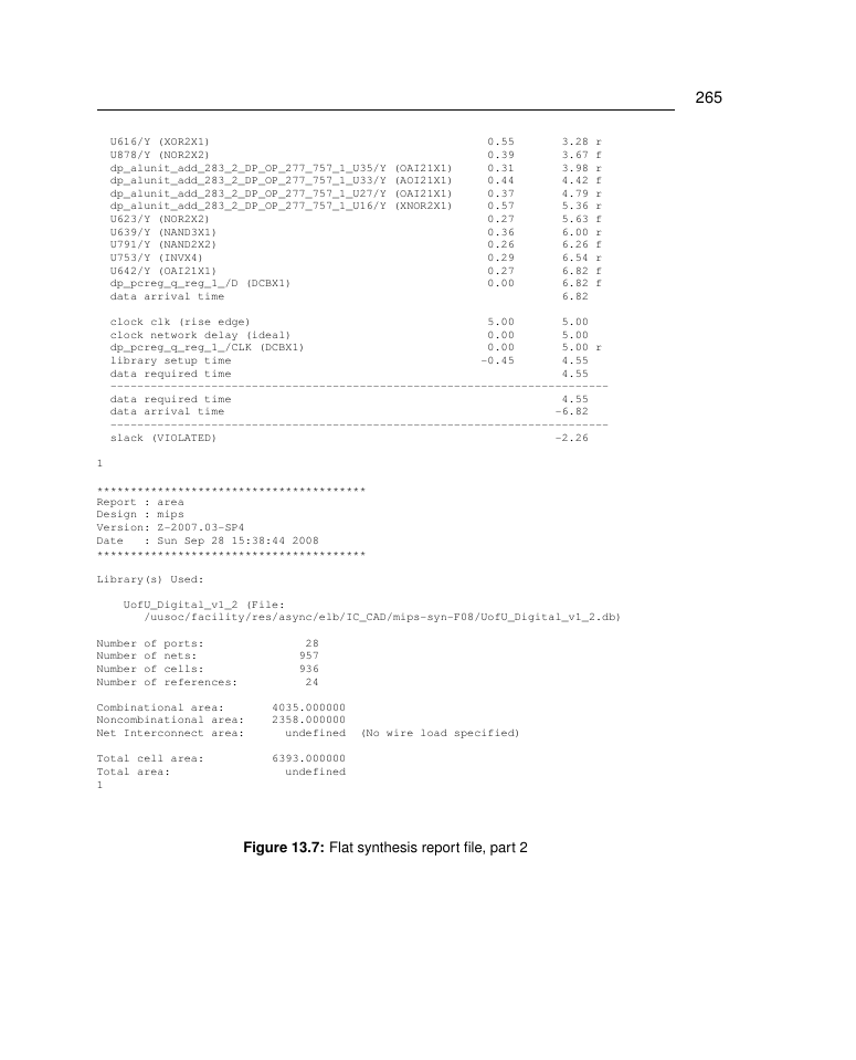
Figure 13.6: Flat synthesis report file, part 1
�
265
U616/Y (XOR2X1)
U878/Y (NOR2X2)
dp_alunit_add_283_2_DP_OP_277_757_1_U35/Y (OAI21X1)
dp_alunit_add_283_2_DP_OP_277_757_1_U33/Y (AOI21X1)
dp_alunit_add_283_2_DP_OP_277_757_1_U27/Y (OAI21X1)
dp_alunit_add_283_2_DP_OP_277_757_1_U16/Y (XNOR2X1)
U623/Y (NOR2X2)
U639/Y (NAND3X1)
U791/Y (NAND2X2)
U753/Y (INVX4)
U642/Y (OAI21X1)
dp_pcreg_q_reg_1_/D (DCBX1)
data arrival time
0.55
0.39
0.31
0.44
0.37
0.57
0.27
0.36
0.26
0.29
0.27
0.00
3.28 r
3.67 f
3.98 r
4.42 f
4.79 r
5.36 r
5.63 f
6.00 r
6.26 f
6.54 r
6.82 f
6.82 f
6.82
clock clk (rise edge)
clock network delay (ideal)
dp_pcreg_q_reg_1_/CLK (DCBX1)
library setup time
data required time
--------------------------------------------------------------------------
data required time
data arrival time
--------------------------------------------------------------------------
slack (VIOLATED)
5.00
5.00
5.00 r
4.55
4.55
5.00
0.00
0.00
-0.45
4.55
-6.82
-2.26
1
****************************************
Report : area
Design : mips
Version: Z-2007.03-SP4
Date
****************************************
: Sun Sep 28 15:38:44 2008
Library(s) Used:
UofU_Digital_v1_2 (File:
/uusoc/facility/res/async/elb/IC_CAD/mips-syn-F08/UofU_Digital_v1_2.db)
Number of ports:
Number of nets:
Number of cells:
Number of references:
28
957
936
24
Combinational area:
Noncombinational area:
Net Interconnect area:
4035.000000
2358.000000
undefined
Total cell area:
Total area:
1
6393.000000
undefined
(No wire load specified)
Figure 13.7: Flat synthesis report file, part 2
�
266
CHAPTER 13: Design Example
Encounter Input configuration file
Erik Brunvand, University of Utah
{../mips_struct.v}
{mips}
################################################
#
#
#
#
################################################
global rda_Input
#
#########################################################
# Here are the parts you need to update for your design
#########################################################
#
# Your input is structural verilog. Set the top module name
# and also give the .sdc file you used in synthesis for the
# clock timing constraints.
set rda_Input(ui_netlist)
set rda_Input(ui_topcell)
set rda_Input(ui_timingcon_file) {../mips_struct.sdc}
#
# Leave min and max empty if you have only one timing library
# (space-separated if you have more than one)
set rda_Input(ui_timelib)
set rda_Input(ui_timelib,min)
set rda_Input(ui_timelib,max)
#
# Set the name of your lef file or files
# (space-separated if you have more than one).
set rda_Input(ui_leffile) {UofU_Digital_v1_2.lef}
#
# Include the footprints of your cells that fit these uses. Delay
# can be an inverter or a buffer. Leave buf blank if you don’t
# have a non-inverting buffer. These are the "footprints" in
# the .lib file, not the cell names.
set rda_Input(ui_buf_footprint)
{buf}
set rda_Input(ui_delay_footprint)
{buf}
set rda_Input(ui_inv_footprint)
{inv}
set rda_Input(ui_cts_cell_footprint) {inv}
#
... Additional lines deleted
{UofU_Digital_v1_2.lib}
{}
{}
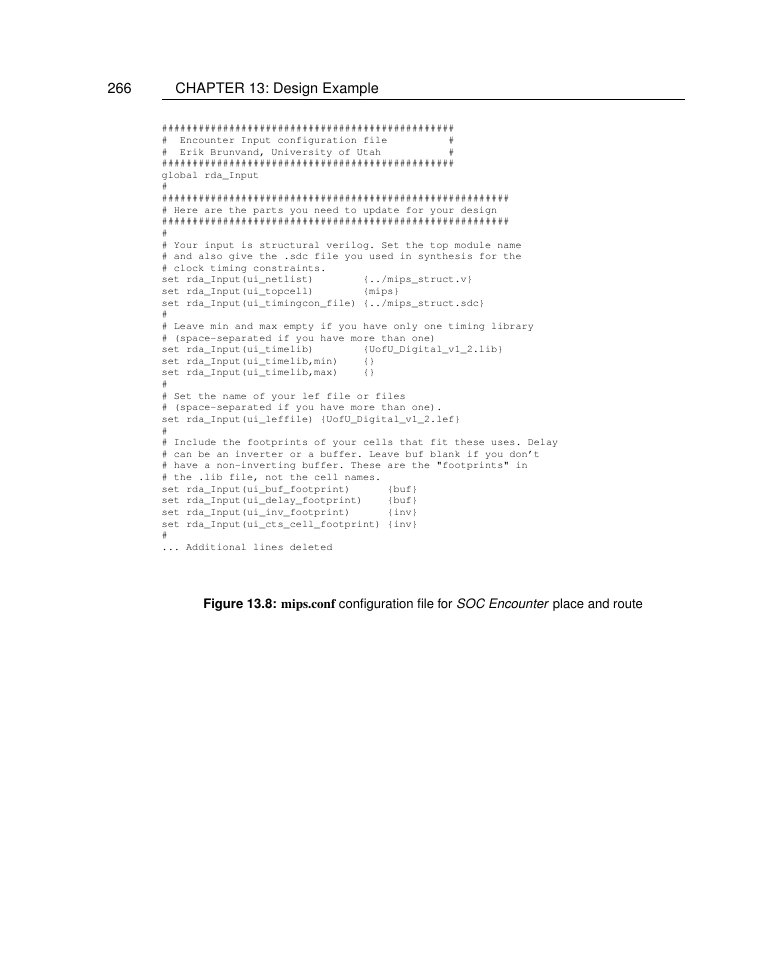
Figure 13.8: mips.conf configuration file for SOC Encounter place and route
�




 2023年江西萍乡中考道德与法治真题及答案.doc
 2012年重庆南川中考生物真题及答案.doc
 2013年江西师范大学地理学综合及文艺理论基础考研真题.doc
 2020年四川甘孜小升初语文真题及答案I卷.doc
 2020年注册岩土工程师专业基础考试真题及答案.doc
 2023-2024学年福建省厦门市九年级上学期数学月考试题及答案.doc
 2021-2022学年辽宁省沈阳市大东区九年级上学期语文期末试题及答案.doc
 2022-2023学年北京东城区初三第一学期物理期末试卷及答案.doc
 2018上半年江西教师资格初中地理学科知识与教学能力真题及答案.doc
 2012年河北国家公务员申论考试真题及答案-省级.doc
 2020-2021学年江苏省扬州市江都区邵樊片九年级上学期数学第一次质量检测试题及答案.doc
 2022下半年黑龙江教师资格证中学综合素质真题及答案.doc