DT0101
Design tip
Setting up single-tap and double-tap recognition
with ST’s MEMS accelerometers
By Vladimir JANOUSEK, Zuzana JIRANKOVA, and Petr STUKJUNGER
LIS2DW12
LIS2DH12
Main components
MEMS digital output motion sensor:
high-performance ultra-low-power 3-axis "femto" accelerometer
MEMS digital output motion sensor:
ultra-low-power high-performance 3-axis "femto" accelerometer
Purpose and benefits
This design tip explains how to enable and personalize the single-tap and double-tap
recognition feature of MEMS accelerometers from STMicroelectronics.
First we explain this embedded feature, what it does and how it can be parameterized.
Then we discuss the impact of its parameters on detection results. Finally, we show
using the two most frequently used ST accelerometers, LIS2DW12 and LIS2DH12,
exact settings and example source codes for implementing the single-tap and double-
tap recognition feature in applications.
Description
The single-tap and double-tap recognition feature allows detecting actions similar to the
single click and double click of a mouse. The difference in using a MEMS accelerometer
is that there is no need for a mechanical button to be pressed. This feature allows easy
implementation of user interfaces of wearable, portable and other devices. Replacing the
mechanical button brings more robust, user-friendly and cheaper design as well as the
possibility of a higher degree of system integration.
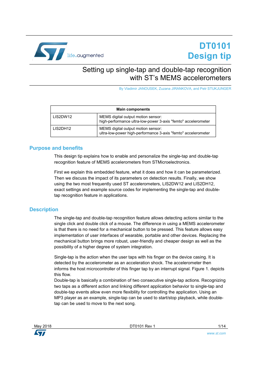
Single-tap is the action when the user taps with his finger on the device casing. It is
detected by the accelerometer as an acceleration shock. The accelerometer then
informs the host microcontroller of this finger tap by an interrupt signal. Figure 1. depicts
this flow.
Double-tap is basically a combination of two consecutive single-tap actions. Recognizing
two taps as a different action and linking different application behavior to single-tap and
double-tap events allow even more flexibility for controlling the application. Using an
MP3 player as an example, single-tap can be used to start/stop playback, while double-
tap can be used to move to the next song.
May 2018
DT0101 Rev 1
1/14
www.st.com
�
Figure 1. Tap event recognition flow
Tap
Acceleration
Shock
Tap
Recognition
INT
User action
handling
MEMS
accelerometer
Microcontroller
Parameterization
For single-tap recognition there are two parameters to set up – threshold and shock
time window.
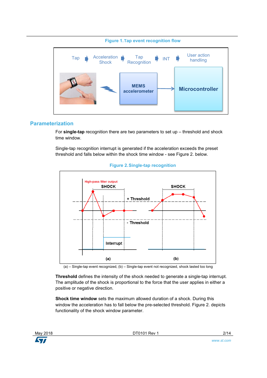
Single-tap recognition interrupt is generated if the acceleration exceeds the preset
threshold and falls below within the shock time window - see Figure 2. below.
Figure 2. Single-tap recognition
(a) – Single-tap event recognized, (b) – Single-tap event not recognized, shock lasted too long
Threshold defines the intensity of the shock needed to generate a single-tap interrupt.
The amplitude of the shock is proportional to the force that the user applies in either a
positive or negative direction.
Shock time window sets the maximum allowed duration of a shock. During this
window the acceleration has to fall below the pre-selected threshold. Figure 2. depicts
functionality of the shock window parameter.
May 2018
DT0101 Rev 1
2/14
www.st.com
�
For double-tap recognition there are four parameters to set up. Besides the threshold
and shock time window which are the same as for single-tap recognition, there are also
the quiet time window and latency time window parameters.
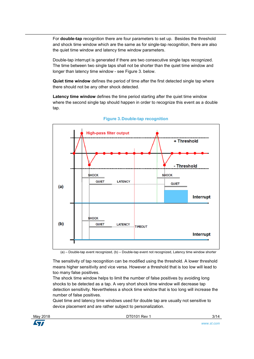
Double-tap interrupt is generated if there are two consecutive single taps recognized.
The time between two single taps shall not be shorter than the quiet time window and
longer than latency time window - see Figure 3. below.
Quiet time window defines the period of time after the first detected single tap where
there should not be any other shock detected.
Latency time window defines the time period starting after the quiet time window
where the second single tap should happen in order to recognize this event as a double
tap.
Figure 3. Double-tap recognition
(a) – Double-tap event recognized, (b) – Double-tap event not recognized, Latency time window shorter
The sensitivity of tap recognition can be modified using the threshold. A lower threshold
means higher sensitivity and vice versa. However a threshold that is too low will lead to
too many false positives.
The shock time window helps to limit the number of false positives by avoiding long
shocks to be detected as a tap. A very short shock time window will decrease tap
detection sensitivity. Nevertheless a shock time window that is too long will increase the
number of false positives.
Quiet time and latency time windows used for double tap are usually not sensitive to
device placement and are rather subject to personalization.
May 2018
DT0101 Rev 1
3/14
www.st.com
�
For single-tap and double-tap recognition it is usually enough to utilize the lowest full
scale (±2 g), because of the high sensitivity required. In some cases where shocks are
bigger, full scale (±4 g) could be recommended.
Output data rate (ODR) selection also affects tap recognition. As acceleration shocks
generated by tap events are usually short, ODRs of 400 Hz and higher are
recommended. For low-power applications an ODR of 200 Hz could be used, carefully
considering the configuration of the tap parameters.
Single-tap and double-tap recognition has to be always fine-tuned carefully for each
application case. The reason is that each application uses a different mounting for the
sensor – it makes a significant difference whether the device is on a wrist, in a shirt
pocket, on one’s head (headphones) or lying on a table. Each position will change the
acceleration profile generated by a tap action. This has to be considered case-by-case.
A GUI application for evaluation of sensor functionality (e.g. ST’s Unicleo-GUI or Unico)
can greatly help with the process of fine-tuning the parameters of tap recognition.
Single-tap and double-tap in the LIS2DW12 and LIS2DH12
What was described so far is valid for both the LIS2DW12 and LIS2DH12. However
there are some differences between the two sensors in functionality and naming when
using the single-tap and double-tap recognition feature (see Table 1.).
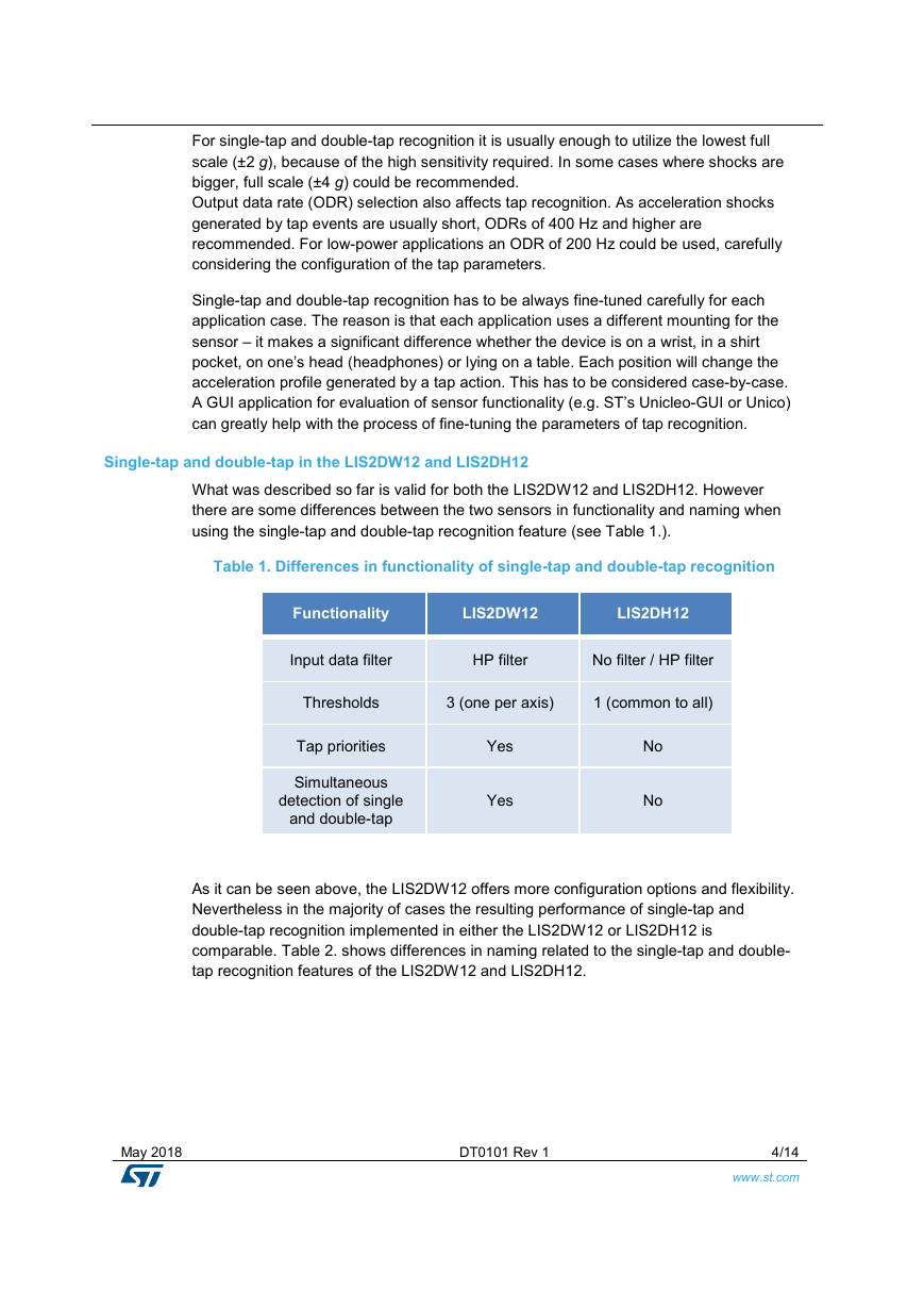
Table 1. Differences in functionality of single-tap and double-tap recognition
Functionality
LIS2DW12
LIS2DH12
Input data filter
HP filter
No filter / HP filter
Thresholds
3 (one per axis)
1 (common to all)
Tap priorities
Simultaneous
detection of single
and double-tap
Yes
Yes
No
No
As it can be seen above, the LIS2DW12 offers more configuration options and flexibility.
Nevertheless in the majority of cases the resulting performance of single-tap and
double-tap recognition implemented in either the LIS2DW12 or LIS2DH12 is
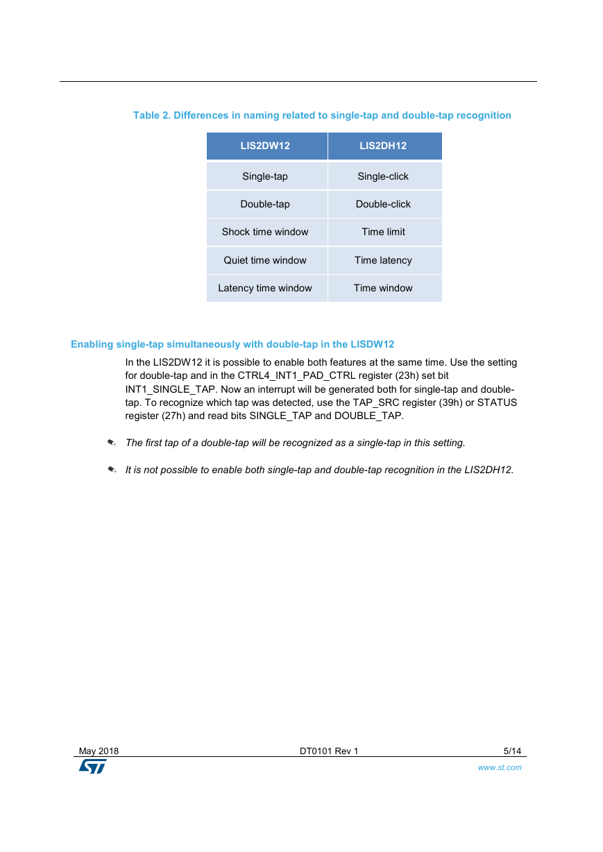
comparable. Table 2. shows differences in naming related to the single-tap and double-
tap recognition features of the LIS2DW12 and LIS2DH12.
May 2018
DT0101 Rev 1
4/14
www.st.com
�
Table 2. Differences in naming related to single-tap and double-tap recognition
LIS2DW12
Single-tap
Double-tap
LIS2DH12
Single-click
Double-click
Shock time window
Time limit
Quiet time window
Time latency
Latency time window
Time window
Enabling single-tap simultaneously with double-tap in the LISDW12
In the LIS2DW12 it is possible to enable both features at the same time. Use the setting
for double-tap and in the CTRL4_INT1_PAD_CTRL register (23h) set bit
INT1_SINGLE_TAP. Now an interrupt will be generated both for single-tap and double-
tap. To recognize which tap was detected, use the TAP_SRC register (39h) or STATUS
register (27h) and read bits SINGLE_TAP and DOUBLE_TAP.
✎ The first tap of a double-tap will be recognized as a single-tap in this setting.
✎ It is not possible to enable both single-tap and double-tap recognition in the LIS2DH12.
May 2018
DT0101 Rev 1
5/14
www.st.com
�
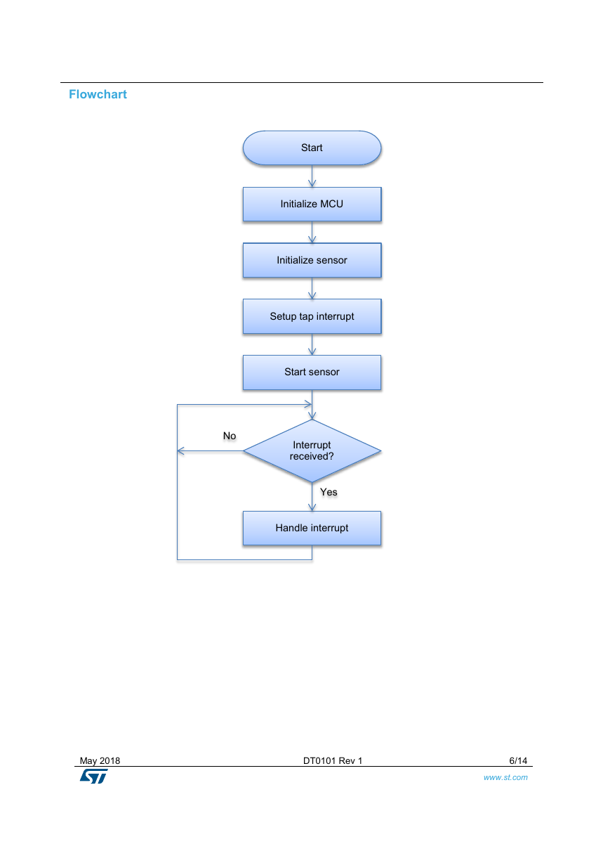
Flowchart
Start
Initialize MCU
Initialize sensor
Setup tap interrupt
Start sensor
No
Interrupt
received?
Yes
Handle interrupt
May 2018
DT0101 Rev 1
6/14
www.st.com
�
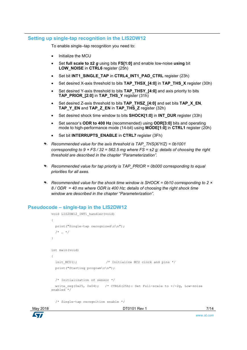
Setting up single-tap recognition in the LIS2DW12
To enable single–tap recognition you need to:
Initialize the MCU
•
• Set full scale to ±2 g using bits FS[1:0] and enable low-noise using bit
LOW_NOISE in CTRL6 register (25h)
• Set bit INT1_SINGLE_TAP in CTRL4_INT1_PAD_CTRL register (23h)
• Set desired X-axis threshold to bits TAP_THSX_[4:0] in TAP_THS_X register (30h)
• Set desired Y-axis threshold to bits TAP_THSY_[4:0] and axis priority to bits
TAP_PRIOR_[2:0] in TAP_THS_Y register (31h)
• Set desired Z-axis threshold to bits TAP_THSZ_[4:0] and set bits TAP_X_EN,
TAP_Y_EN and TAP_Z_EN in TAP_THS_Z register (32h)
• Set desired shock time window to bits SHOCK[1:0] in INT_DUR register (33h)
• Set sensor’s ODR to 400 Hz (recommended) using ODR[3:0] bits and operating
mode to high-performance mode (14-bit) using MODE[1:0] in CTRL1 register (20h)
• Set bit INTERRUPTS_ENABLE in CTRL7 register (3Fh)
✎ Recommended value for the axis threshold is TAP_THS(X/Y/Z) = 0b1001
corresponding to 9 × FS / 32 = 562.5 mg where FS = ±2 g; details of choosing the right
threshold are described in the chapter “Parameterization”.
✎ Recommended value for tap priority is TAP_PRIOR = 0b000 corresponding to equal
priorities for all axes.
✎ Recommended value for the shock time window is SHOCK = 0b10 corresponding to 2 ×
8 / ODR = 40 ms where ODR is 400 Hz; details of choosing the right shock time
window are described in the chapter “Parameterization”.
Pseudocode – single-tap in the LIS2DW12
void LIS2DW12_INT1_handler(void)
{
print("Single-tap recognized\r\n");
/* … */
}
int main(void)
{
init_MCU();
print("Starting program\r\n");
/* Initialization of sensor */
write_reg(0x25, 0x04); /* CTRL6(25h): Set Full-scale to +/-2g, Low-noise
enabled */
/* Single-tap recognition enable */
/* Initialize MCU clock and pins */
May 2018
DT0101 Rev 1
7/14
www.st.com
�
write_reg(0x23, 0x40); /* CTRL4_INT1_PAD_CTRL(23h): Enable Single-tap
interrupt */
write_reg(0x30, 0x09); /* TAP_THS_X (30h): Threshold on X */
write_reg(0x31, 0x09); /* TAP_THS_Y (31h): Threshold on Y and default
priority*/
write_reg(0x32, 0xe9); /* TAP_THS_Z (32h): Threshold on Z and enable all axes
in tap recognition */
write_reg(0x33, 0x02); /* INT_DUR (33h): Shock duration */
/* Start sensor */
write_reg(0x20, 0x74); /* CTRL1(20h): Set ODR 400Hz, High performance mode
(14 bit) */
delay(3); /* Settling time ( 1 sample, i.e. 1/ODR ) */
write_reg(0x3f, 0x20); /* CTRL7 (3Fh): Enable interrupts */
while (1)
{
/* … */
}
}
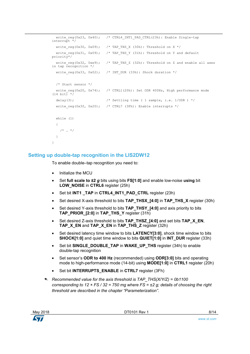
Setting up double-tap recognition in the LIS2DW12
To enable double–tap recognition you need to:
Initialize the MCU
•
• Set full scale to ±2 g bits using bits FS[1:0] and enable low-noise using bit
LOW_NOISE in CTRL6 register (25h)
• Set bit INT1 _TAP in CTRL4_INT1_PAD_CTRL register (23h)
• Set desired X-axis threshold to bits TAP_THSX_[4:0] in TAP_THS_X register (30h)
• Set desired Y-axis threshold to bits TAP_THSY_[4:0] and axis priority to bits
TAP_PRIOR_[2:0] in TAP_THS_Y register (31h)
• Set desired Z-axis threshold to bits TAP_THSZ_[4:0] and set bits TAP_X_EN,
TAP_X_EN and TAP_X_EN in TAP_THS_Z register (32h)
• Set desired latency time window to bits LATENCY[3:0], shock time window to bits
SHOCK[1:0] and quiet time window to bits QUIET[1:0] in INT_DUR register (33h)
• Set bit SINGLE_DOUBLE_TAP in WAKE_UP_THS register (34h) to enable
double-tap recognition
• Set sensor’s ODR to 400 Hz (recommended) using ODR[3:0] bits and operating
mode to high-performance mode (14-bit) using MODE[1:0] in CTRL1 register (20h)
• Set bit INTERRUPTS_ENABLE in CTRL7 register (3Fh)
✎ Recommended value for the axis threshold is TAP_THS(X/Y/Z) = 0b1100
corresponding to 12 × FS / 32 = 750 mg where FS = ±2 g; details of choosing the right
threshold are described in the chapter “Parameterization”.
May 2018
DT0101 Rev 1
8/14
www.st.com
�


 2023年江西萍乡中考道德与法治真题及答案.doc
 2012年重庆南川中考生物真题及答案.doc
 2013年江西师范大学地理学综合及文艺理论基础考研真题.doc
 2020年四川甘孜小升初语文真题及答案I卷.doc
 2020年注册岩土工程师专业基础考试真题及答案.doc
 2023-2024学年福建省厦门市九年级上学期数学月考试题及答案.doc
 2021-2022学年辽宁省沈阳市大东区九年级上学期语文期末试题及答案.doc
 2022-2023学年北京东城区初三第一学期物理期末试卷及答案.doc
 2018上半年江西教师资格初中地理学科知识与教学能力真题及答案.doc
 2012年河北国家公务员申论考试真题及答案-省级.doc
 2020-2021学年江苏省扬州市江都区邵樊片九年级上学期数学第一次质量检测试题及答案.doc
 2022下半年黑龙江教师资格证中学综合素质真题及答案.doc