Moxa Tech Note
The Secrets of UART FIFO
Casper Yang, Senior Product Manager
support@moxa.com
A UART (universal asynchronous receiver transmitter) is a key component of
RS-232/422/485 serial communication hardware, and documents that introduce
UARTs are readily available. A UART’s FIFO buffer is designed to improve
communication performance, although if it is configured incorrectly, you may find
that your communication performance is degraded. In this paper we give a simple
introduction to the UART FIFO, discuss how it influences communication behavior,
and provide instructions on the proper way to configure a FIFO.
Why FIFO?
A FIFO (First In First Out) is a UART buffer that forces each byte of your serial
communication to be passed on in the order received. For an 8250 or 16450 UART,
for example, the FIFO has a size of only one byte. This means that the UART will
issue an interrupt to the system for each byte of data received, which uses a lot of
CPU resources. If you don’t read the data from the UART in time, the next byte will
overwrite the data. For higher baudrate applications (higher than 115200 bps, for
example), a 1-byte limitation will make it more likely that data will be lost.
Copyright © 2009 Moxa Inc.
Released on Oct.01, 2009
About Moxa
Moxa manufactures one of the world’s leading brands of device networking solutions. Products include serial
boards, USB-to-serial hubs, media converters, device servers, embedded computers, Ethernet I/O servers,
terminal servers, Modbus gateways, industrial switches, and Ethernet-to-fiber converters. Our products are key
components of many networking applications, including industrial automation, manufacturing, POS, and medical
treatment facilities.
How to Contact Moxa
Tel:
1-714-528-6777
Fax: 1-714-528-6778
Web: www.moxa.com
Email: info@moxa.com
This document was produced by the Moxa Technical Writing Center (TWC). Please send your comments or
suggestions about this or other Moxa documents to twc@moxa.com.
�
Moxa Tech Note
The Secrets of UART FIFO
The Trouble with FIFO—Timeout Design
The data loss that can result from a 1-byte limitation on FIFO size is why most
advanced UARTs, such as the 16550A, support a FIFO size of 16 bytes or more.
With a larger FIFO, for each interrupt that is issued you can often read all of the
data at one time, which saves system CPU resources since you won’t be reading
data all the time. This is good for large data transfers, but may not be good for real
time control. The frequency with which interrupts are issued can be controlled by
adjusting the RTL (receive trigger level) value. When the amount of received data
reaches the RTL, the UART will issue an interrupt. The 16550A with its 16-byte FIFO
supports 4 RTL levels: 1, 4, 8, and 14. This means an interrupt will be issued when
the UART FIFO receives 1, 4, 8, or 14 bytes of data. Note that the highest level is
14 instead of 16 to prevent overflow.
Another problem you need to consider is this: If the amount of received data hasn’t
reached the RTL value, when will the UART issue an interrupt? For example, if you
configure the trigger level to 14 (the default), but the device only sends 4 bytes
(substantially lower than 14), how long will you need to wait until the UART issues
the receive interrupt?
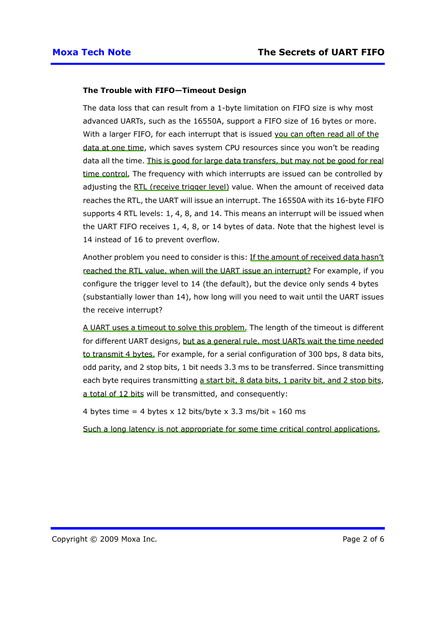
A UART uses a timeout to solve this problem. The length of the timeout is different
for different UART designs, but as a general rule, most UARTs wait the time needed
to transmit 4 bytes. For example, for a serial configuration of 300 bps, 8 data bits,
odd parity, and 2 stop bits, 1 bit needs 3.3 ms to be transferred. Since transmitting
each byte requires transmitting a start bit, 8 data bits, 1 parity bit, and 2 stop bits,
a total of 12 bits will be transmitted, and consequently:
4 bytes time = 4 bytes x 12 bits/byte x 3.3 ms/bit ≈ 160 ms
Such a long latency is not appropriate for some time critical control applications.
Copyright © 2009 Moxa Inc.
Page 2 of 6
�
Moxa Tech Note
The Secrets of UART FIFO
RX
Data (< RTL)
Interrupt
Data (< RTL)
ISR
FIFO timeout causes latency.
Fig. 2: FIFO Timeout Causes Latency
Receiving—Throughput or Latency?
In serial communication, there is a tradeoff between throughput and latency, and
you can only choose one, which is fortunate since most applications only need one
of the two. Applications such as downloading firmware or file downloads in CNC
control only need good throughput. For such applications, you can simply configure
the UART to the highest RTL value (for example, 14 bytes for the 16550A). But for
other applications, you need to disable the FIFO or set the RTL value to 1 to get
good (i.e., short) latency. This means that you need to respond as soon as possible
when you receive data from the serial line. In software flow control for example, if
you receive an XOFF character, you need to stop transmitting data immediately.
Transmitting—Slow Throughput with Lag for Slow Devices
The above discussion focuses on receiving data, but you also need to control how
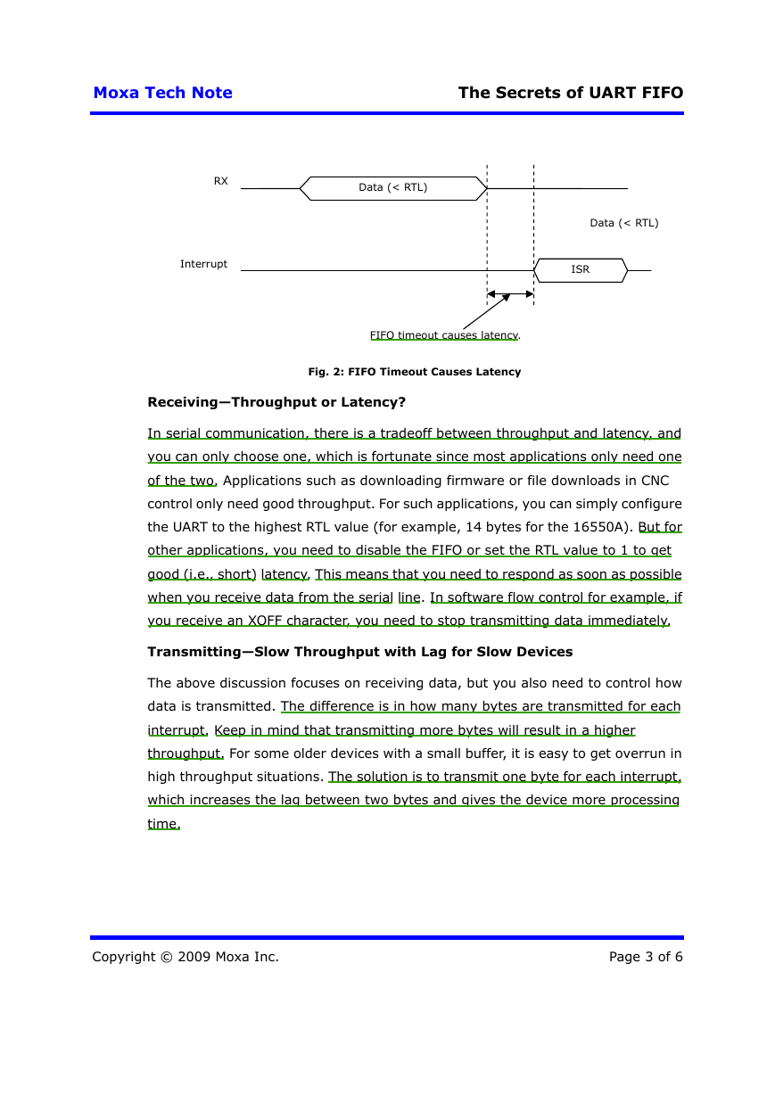
data is transmitted. The difference is in how many bytes are transmitted for each
interrupt. Keep in mind that transmitting more bytes will result in a higher
throughput. For some older devices with a small buffer, it is easy to get overrun in
high throughput situations. The solution is to transmit one byte for each interrupt,
which increases the lag between two bytes and gives the device more processing
time.
Copyright © 2009 Moxa Inc.
Page 3 of 6
�
Moxa Tech Note
The Secrets of UART FIFO
Tx
Datax1
Datax1
Datax1
Interrupt
ISR
ISR
Transmit Lag, slow throughput
Tx
Datax3
Interrupt
ISR
Fig. 3: A FIFO provides better Tx throughput, and fewer
interrupts means using fewer CPU resources.
Better Receive Throughput—High/Low Water for Flow Control
Many advanced UARTs provide an on-chip flow control function that uses both a
receive high water level (RBH) and low water level (RBL), as opposed to just one
trigger level. If a UART only supports one receive trigger, it will issue an interrupt
and turn off the RTS when the length of the data reaches a certain level, and it will
turn on the RTS when all of the data has been read. At that moment there will be no
data in the FIFO and the system will waste time waiting for additional data. For
better throughput, set the RBL value to a non-zero number. For example, if you set
RBH to 120 bytes and set RBL to 16 bytes for a UART with a 128-byte FIFO, the RTS
will switch off when the received data length is greater then 120 bytes. The RTS will
turn on again when fewer than 16 bytes are in the FIFO after the system moves
some data to memory. The UART also provides an interrupt level (RBI) setting,
which is equal to a traditional trigger level. For this UART, this means that the
timing for issuing an interrupt and turning off the RTS can be different (note that
traditional UARTs only use the RTL value).
Copyright © 2009 Moxa Inc.
Page 4 of 6
�
Moxa Tech Note
The Secrets of UART FIFO
Better Transmit Throughput—High/Low Water
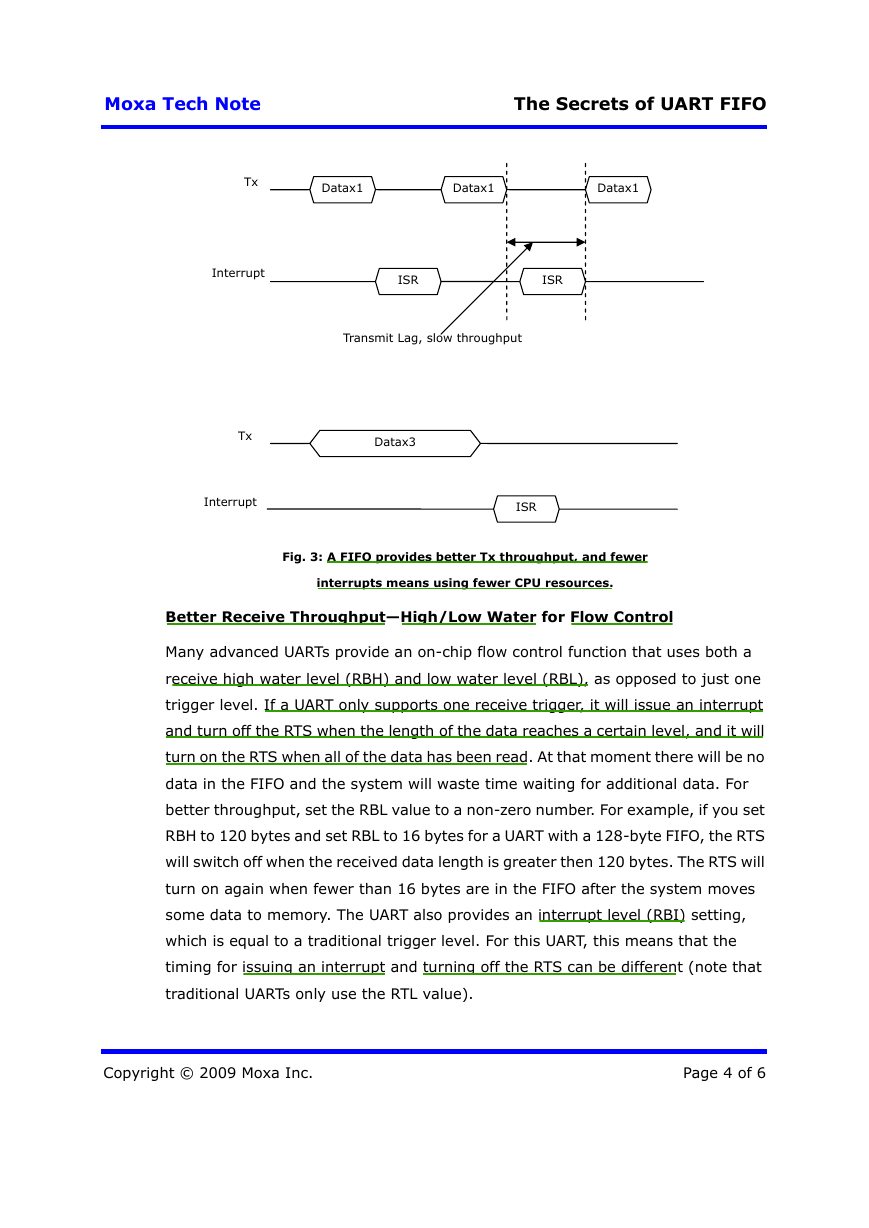
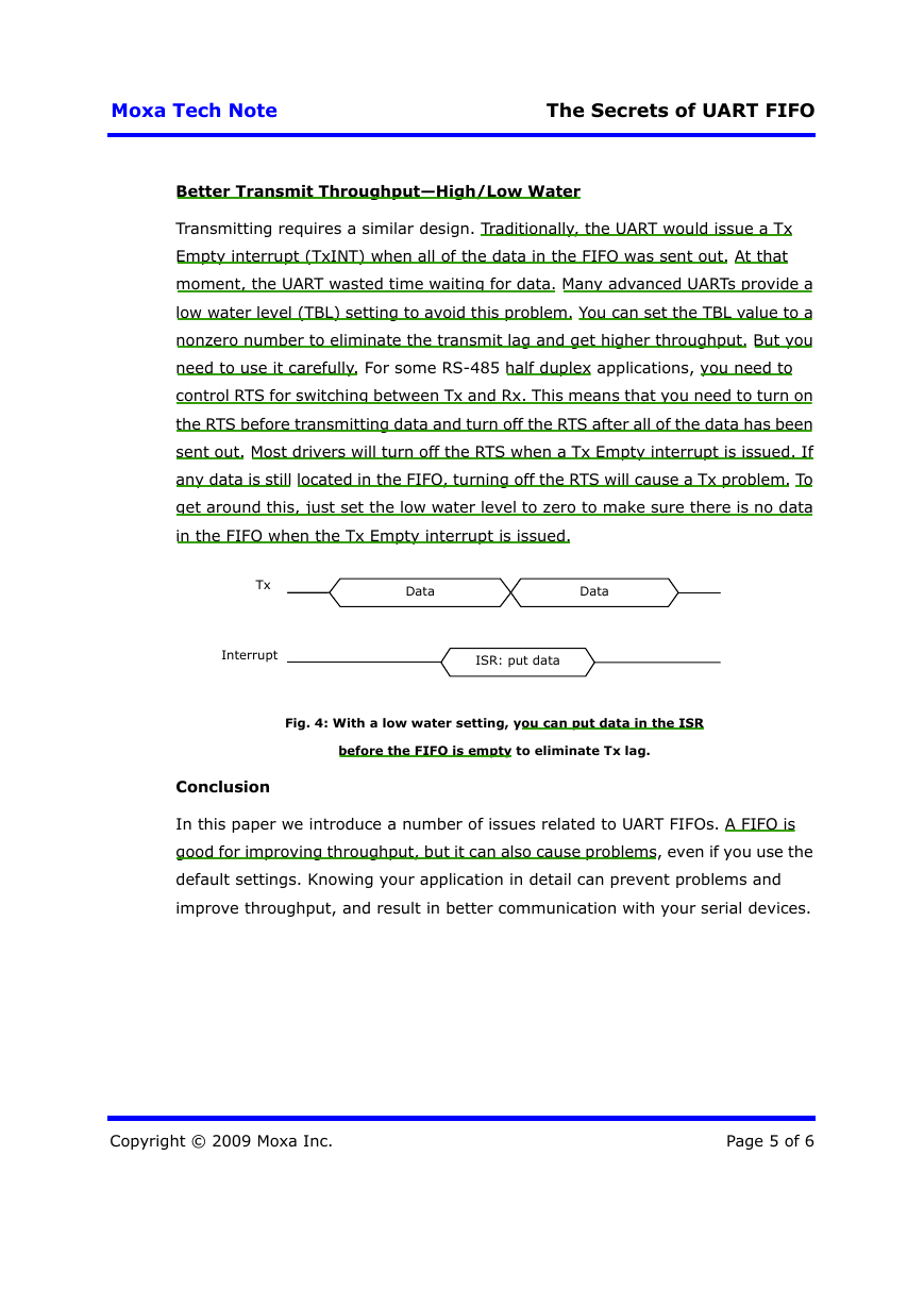
Transmitting requires a similar design. Traditionally, the UART would issue a Tx
Empty interrupt (TxINT) when all of the data in the FIFO was sent out. At that
moment, the UART wasted time waiting for data. Many advanced UARTs provide a
low water level (TBL) setting to avoid this problem. You can set the TBL value to a
nonzero number to eliminate the transmit lag and get higher throughput. But you
need to use it carefully. For some RS-485 half duplex applications, you need to
control RTS for switching between Tx and Rx. This means that you need to turn on
the RTS before transmitting data and turn off the RTS after all of the data has been
sent out. Most drivers will turn off the RTS when a Tx Empty interrupt is issued. If
any data is still located in the FIFO, turning off the RTS will cause a Tx problem. To
get around this, just set the low water level to zero to make sure there is no data
in the FIFO when the Tx Empty interrupt is issued.
Tx
Interrupt
Conclusion
Data
Data
ISR: put data
Fig. 4: With a low water setting, you can put data in the ISR
before the FIFO is empty to eliminate Tx lag.
In this paper we introduce a number of issues related to UART FIFOs. A FIFO is
good for improving throughput, but it can also cause problems, even if you use the
default settings. Knowing your application in detail can prevent problems and
improve throughput, and result in better communication with your serial devices.
Copyright © 2009 Moxa Inc.
Page 5 of 6
�
Moxa Tech Note
FAQ Question
1 How can I get the best Rx latency?
2 If my serial device is slow and has a
small buffer, what can I do to prevent
data overflow?
3 Is there any way to get better Rx
throughput or eliminate Rx lag?
The Secrets of UART FIFO
Answer
Disable the FIFO, or set the Rx trigger
level to 1.
Disable the FIFO, or set RTL=1 and
send one byte for each interrupt.
Use an advanced UART with RBH and
RBL, and set the RBL to a nonzero
value.
4 Is there any way to get better Tx
throughput or eliminate the Tx lag?
Use an advanced UART with TBH and
TBL, and set TBL to a nonzero value.
5 What is the proper FIFO setting when
working with RS-485 with RTS flow
control?
Set TBL to zero if using an advanced
UART.
6 I’m using XON/XOFF flow control but
am getting data overflow. How can I
solve this problem?
For a UART that does not have on-chip
XON/XOFF flow control, try disabling
the FIFO.
Copyright © 2009 Moxa Inc.
Page 6 of 6
�


 2023年江西萍乡中考道德与法治真题及答案.doc
 2012年重庆南川中考生物真题及答案.doc
 2013年江西师范大学地理学综合及文艺理论基础考研真题.doc
 2020年四川甘孜小升初语文真题及答案I卷.doc
 2020年注册岩土工程师专业基础考试真题及答案.doc
 2023-2024学年福建省厦门市九年级上学期数学月考试题及答案.doc
 2021-2022学年辽宁省沈阳市大东区九年级上学期语文期末试题及答案.doc
 2022-2023学年北京东城区初三第一学期物理期末试卷及答案.doc
 2018上半年江西教师资格初中地理学科知识与教学能力真题及答案.doc
 2012年河北国家公务员申论考试真题及答案-省级.doc
 2020-2021学年江苏省扬州市江都区邵樊片九年级上学期数学第一次质量检测试题及答案.doc
 2022下半年黑龙江教师资格证中学综合素质真题及答案.doc