logo资料库

DDR4 SDRAM SODIMM Design Specification.pdf

第1页 / 共44页
第2页 / 共44页
第3页 / 共44页
第4页 / 共44页
第5页 / 共44页
第6页 / 共44页
第7页 / 共44页
第8页 / 共44页
资料共44页,剩余部分请下载后查看
1 Product Description
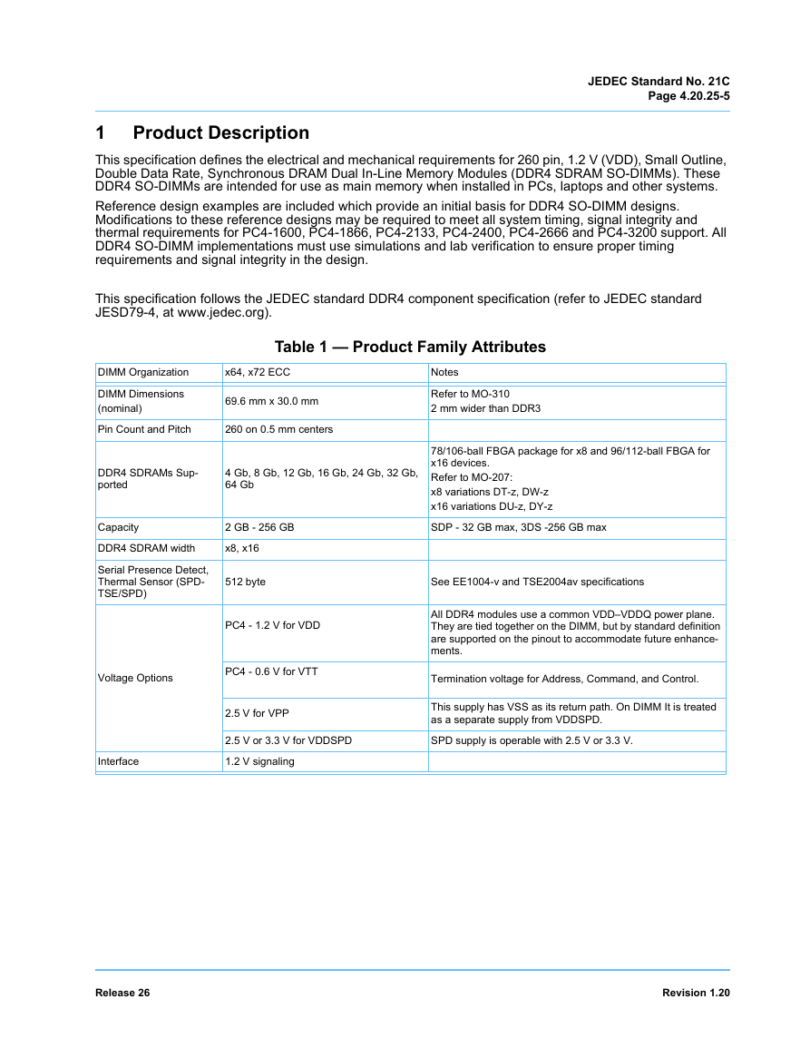
Table 1 — Product Family Attributes
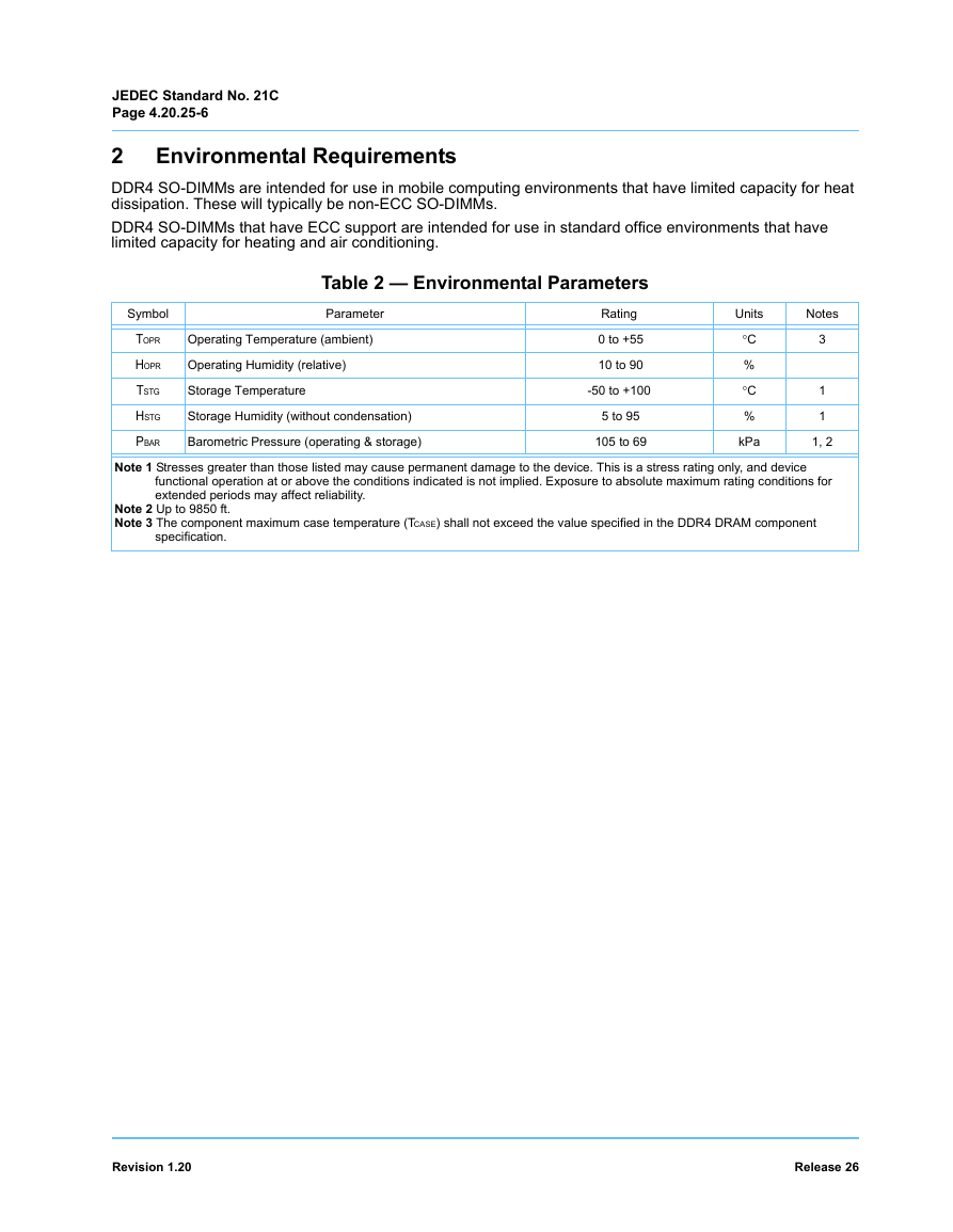
2 Environmental Requirements
Table 2 — Environmental Parameters
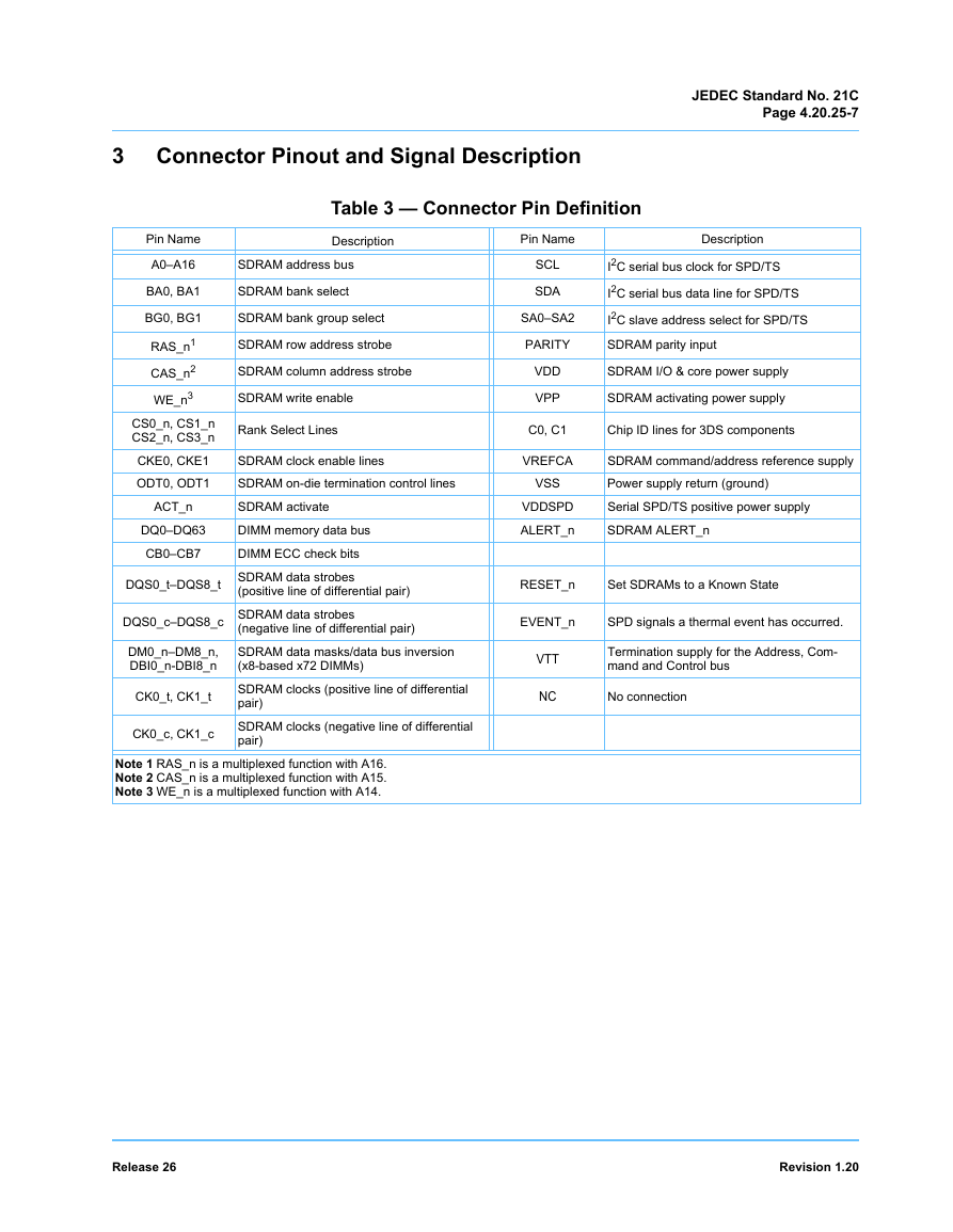
3 Connector Pinout and Signal Description
Table 3 — Connector Pin Definition
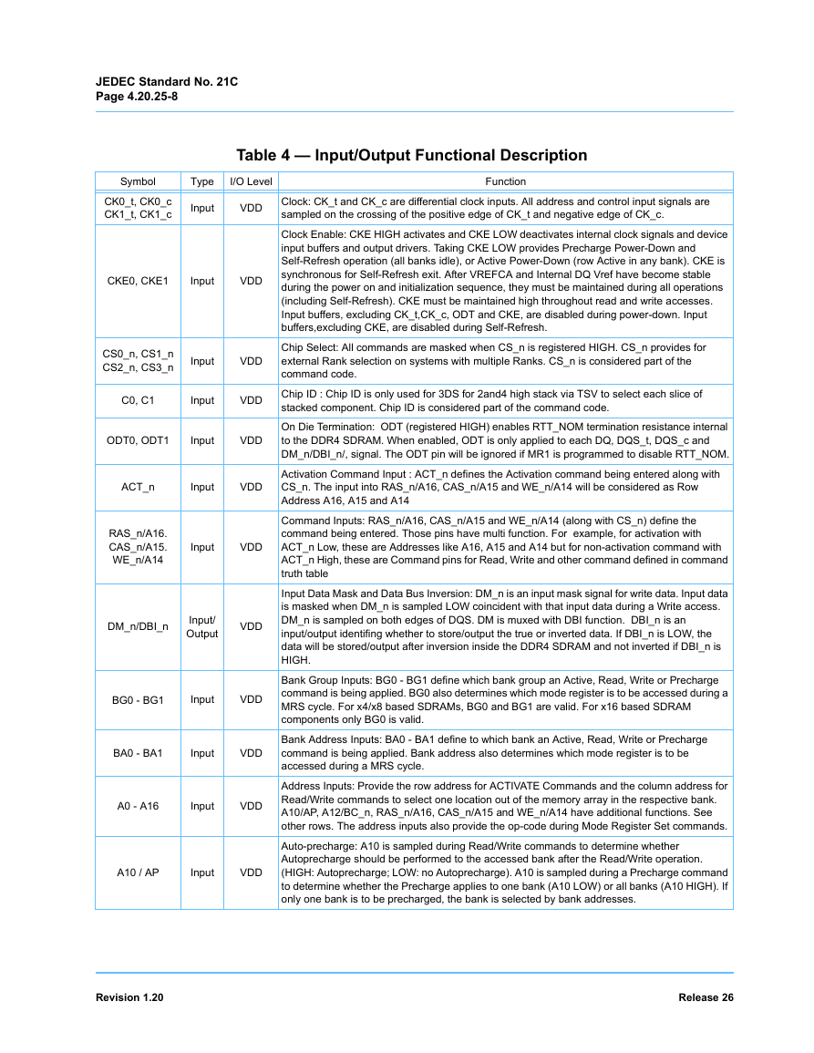
Table 4 — Input/Output Functional Description
3.1 DDR4 SO-DIMM Connector Pin Assignments
Table 5 — DDR4 SO-DIMM 260 Pin Connector Pin Wiring Assignments
4 Power Details
4.1 DIMM Voltage Requirements
Table 6 — DDR4 SO-DIMM DC Operating Voltage1,2,3 - 1.2 V operation
4.2 Rules for Power-Up Sequence
Figure 1 — Graphical View of Recommended Power Sequence
Figure 2 — Graphical View of Recommended Power Down Sequence
4.3 Feed Through Voltage (VFT)
5 Component Details
Figure 3 — DIMM Ball Patterns for DDR4 SDRAM Components
Table 7 — DDR4 x8 SDRAM DIMM Pad Array
Table 8 — DDR4 x16 SDRAM DIMM Pad Array
5.1 Component Types and Placement
5.2 Decoupling Guidelines
Table 9 — DDR4 SO-DIMM Decoupling Capacitor Guidelines
6 DIMM Design Details
6.1 Signal Groups
Figure 4 — Example SO-DIMM Fly-By Topology
6.2 Explanation of Net Structure Diagrams
Figure 5 — Net Structure Example
6.3 General Net Structure Routing Rules
Table 10 — CK, CTRL, and ADD/CMD Group Length Matching Rules
Figure 6 — Example Address routing topology
Table 11 — Data and Strobe Group Length Matching Rules
Figure 7 — ALERT_n Wiring Illustration
Figure 8 — Via Compensation Diagram
Table 12 — Plane Referencing
6.4 Address Mirroring
Table 13 — DIMM Wiring Definition for Address Mirroring
6.5 DIMM Routing Space Constraints
Table 14 — Routing Space Constraints
6.6 DIMM Physical Requirements
6.7 Reference Stackups
Table 15 — Preferred 10 Layer Stackup for SO-DIMMs
Table 16 — Preferred 8 Layer Stackup for SO-DIMMs
Table 17 — Preferred 6 Layer Stackup for SO-DIMMs
6.8 Impedance Targets
Table 18 — Impedance Assignments by Signal Type
6.9 SPD Wiring and Placement
Figure 9 — Block Diagram: SPD-TSE/ SPD
6.10 DQ Mapping to Support CRC
Table 19 — SPD DQ Nibble Map for CRC
Table 20 — Nibble/Byte DQ Map Patterns for CRC
Figure 10 — Example of DQ Wiring with Mapping for CRC
Table 21 — Example of DQ Mapping for CRC
7 Serial Presence Detect Component Specification
7.1 Serial Presence Detect Definition
Table 22 — SPD Address Map
Table 23 — Block 0: Base Configuration and DRAM Parameters
8 Product Label
8.1 DDR4 DIMM Label Format for DRAM-only module types
8.2 DDR4 DIMM Label Format for Hybrid module types
9 JEDEC Process
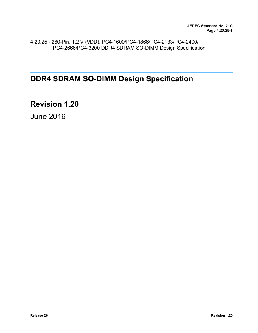
4.20.25 - 260-Pin, 1.2 V (VDD), PC4-1600/PC4-1866/PC4-2133/PC4-2400/ PC4-2666/PC4-3200 DDR4 SDRAM SO-DIMM Design Specification JEDEC Standard No. 21C Page 4.20.25-1 DDR4 SDRAM SO-DIMM Design Specification Revision 1.20 June 2016 Release 26 Revision 1.20
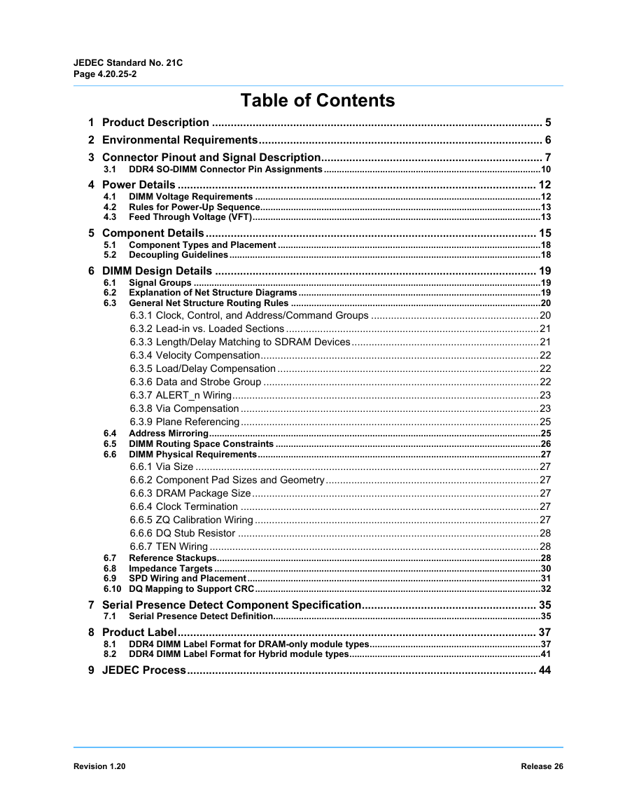
JEDEC Standard No. 21C Page 4.20.25-2 Table of Contents 1 Product Description .......................................................................................................... 5 2 Environmental Requirements........................................................................................... 6 3 Connector Pinout and Signal Description....................................................................... 7 3.1 DDR4 SO-DIMM Connector Pin Assignments.....................................................................................10 4 Power Details ................................................................................................................... 12 4.1 DIMM Voltage Requirements ................................................................................................................12 4.2 Rules for Power-Up Sequence..............................................................................................................13 4.3 Feed Through Voltage (VFT).................................................................................................................13 5 Component Details.......................................................................................................... 15 5.1 Component Types and Placement .......................................................................................................18 5.2 Decoupling Guidelines..........................................................................................................................18 6 DIMM Design Details ....................................................................................................... 19 6.1 Signal Groups ........................................................................................................................................19 6.2 Explanation of Net Structure Diagrams...............................................................................................19 6.3 General Net Structure Routing Rules ..................................................................................................20 6.3.1 Clock, Control, and Address/Command Groups ...........................................................20 6.3.2 Lead-in vs. Loaded Sections .........................................................................................21 6.3.3 Length/Delay Matching to SDRAM Devices..................................................................21 6.3.4 Velocity Compensation..................................................................................................22 6.3.5 Load/Delay Compensation ............................................................................................22 6.3.6 Data and Strobe Group .................................................................................................22 6.3.7 ALERT_n Wiring............................................................................................................23 6.3.8 Via Compensation .........................................................................................................23 6.3.9 Plane Referencing.........................................................................................................25 6.4 Address Mirroring..................................................................................................................................25 6.5 DIMM Routing Space Constraints ........................................................................................................26 6.6 DIMM Physical Requirements...............................................................................................................27 6.6.1 Via Size .........................................................................................................................27 6.6.2 Component Pad Sizes and Geometry...........................................................................27 6.6.3 DRAM Package Size.....................................................................................................27 6.6.4 Clock Termination .........................................................................................................27 6.6.5 ZQ Calibration Wiring ....................................................................................................27 6.6.6 DQ Stub Resistor ..........................................................................................................28 6.6.7 TEN Wiring ....................................................................................................................28 6.7 Reference Stackups...............................................................................................................................28 Impedance Targets ................................................................................................................................30 6.8 6.9 SPD Wiring and Placement...................................................................................................................31 6.10 DQ Mapping to Support CRC................................................................................................................32 7 Serial Presence Detect Component Specification........................................................ 35 Serial Presence Detect Definition.........................................................................................................35 8 Product Label................................................................................................................... 37 8.1 DDR4 DIMM Label Format for DRAM-only module types...................................................................37 8.2 DDR4 DIMM Label Format for Hybrid module types...........................................................................41 9 JEDEC Process................................................................................................................ 44 7.1 Revision 1.20 Release 26
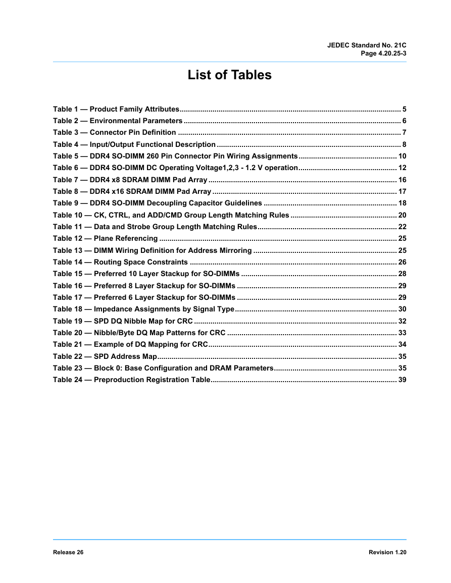
JEDEC Standard No. 21C Page 4.20.25-3 List of Tables Table 1 — Product Family Attributes............................................................................................................ 5 Table 2 — Environmental Parameters .......................................................................................................... 6 Table 3 — Connector Pin Definition ............................................................................................................. 7 Table 4 — Input/Output Functional Description .......................................................................................... 8 Table 5 — DDR4 SO-DIMM 260 Pin Connector Pin Wiring Assignments................................................ 10 Table 6 — DDR4 SO-DIMM DC Operating Voltage1,2,3 - 1.2 V operation................................................ 12 Table 7 — DDR4 x8 SDRAM DIMM Pad Array ............................................................................................ 16 Table 8 — DDR4 x16 SDRAM DIMM Pad Array .......................................................................................... 17 Table 9 — DDR4 SO-DIMM Decoupling Capacitor Guidelines ................................................................. 18 Table 10 — CK, CTRL, and ADD/CMD Group Length Matching Rules .................................................... 20 Table 11 — Data and Strobe Group Length Matching Rules.................................................................... 22 Table 12 — Plane Referencing .................................................................................................................... 25 Table 13 — DIMM Wiring Definition for Address Mirroring ...................................................................... 25 Table 14 — Routing Space Constraints ..................................................................................................... 26 Table 15 — Preferred 10 Layer Stackup for SO-DIMMs ............................................................................ 28 Table 16 — Preferred 8 Layer Stackup for SO-DIMMs .............................................................................. 29 Table 17 — Preferred 6 Layer Stackup for SO-DIMMs .............................................................................. 29 Table 18 — Impedance Assignments by Signal Type............................................................................... 30 Table 19 — SPD DQ Nibble Map for CRC ................................................................................................... 32 Table 20 — Nibble/Byte DQ Map Patterns for CRC ................................................................................... 33 Table 21 — Example of DQ Mapping for CRC............................................................................................ 34 Table 22 — SPD Address Map..................................................................................................................... 35 Table 23 — Block 0: Base Configuration and DRAM Parameters............................................................ 35 Table 24 — Preproduction Registration Table........................................................................................... 39 Release 26 Revision 1.20
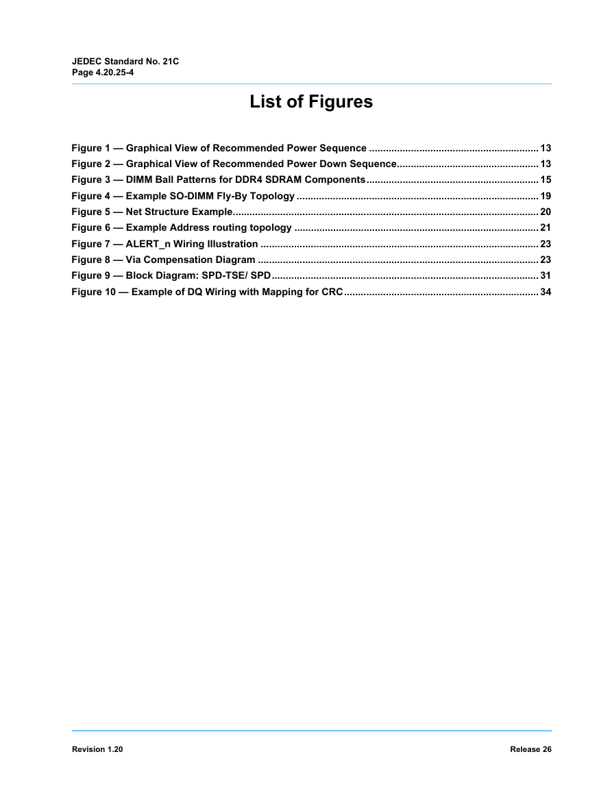
JEDEC Standard No. 21C Page 4.20.25-4 List of Figures Figure 1 — Graphical View of Recommended Power Sequence ............................................................. 13 Figure 2 — Graphical View of Recommended Power Down Sequence................................................... 13 Figure 3 — DIMM Ball Patterns for DDR4 SDRAM Components.............................................................. 15 Figure 4 — Example SO-DIMM Fly-By Topology ....................................................................................... 19 Figure 5 — Net Structure Example.............................................................................................................. 20 Figure 6 — Example Address routing topology ........................................................................................ 21 Figure 7 — ALERT_n Wiring Illustration .................................................................................................... 23 Figure 8 — Via Compensation Diagram ..................................................................................................... 23 Figure 9 — Block Diagram: SPD-TSE/ SPD................................................................................................ 31 Figure 10 — Example of DQ Wiring with Mapping for CRC...................................................................... 34 Revision 1.20 Release 26
JEDEC Standard No. 21C Page 4.20.25-5 Product Description 1 This specification defines the electrical and mechanical requirements for 260 pin, 1.2 V (VDD), Small Outline, Double Data Rate, Synchronous DRAM Dual In-Line Memory Modules (DDR4 SDRAM SO-DIMMs). These DDR4 SO-DIMMs are intended for use as main memory when installed in PCs, laptops and other systems. Reference design examples are included which provide an initial basis for DDR4 SO-DIMM designs. Modifications to these reference designs may be required to meet all system timing, signal integrity and thermal requirements for PC4-1600, PC4-1866, PC4-2133, PC4-2400, PC4-2666 and PC4-3200 support. All DDR4 SO-DIMM implementations must use simulations and lab verification to ensure proper timing requirements and signal integrity in the design. This specification follows the JEDEC standard DDR4 component specification (refer to JEDEC standard JESD79-4, at www.jedec.org). Table 1 — Product Family Attributes DIMM Organization x64, x72 ECC DIMM Dimensions (nominal) 69.6 mm x 30.0 mm Pin Count and Pitch 260 on 0.5 mm centers Notes Refer to MO-310 2 mm wider than DDR3 DDR4 SDRAMs Sup- ported 4 Gb, 8 Gb, 12 Gb, 16 Gb, 24 Gb, 32 Gb, 64 Gb 78/106-ball FBGA package for x8 and 96/112-ball FBGA for x16 devices. Refer to MO-207: x8 variations DT-z, DW-z x16 variations DU-z, DY-z Capacity 2 GB - 256 GB SDP - 32 GB max, 3DS -256 GB max DDR4 SDRAM width x8, x16 Serial Presence Detect, Thermal Sensor (SPD- TSE/SPD) 512 byte PC4 - 1.2 V for VDD Voltage Options PC4 - 0.6 V for VTT 2.5 V for VPP See EE1004-v and TSE2004av specifications All DDR4 modules use a common VDD–VDDQ power plane. They are tied together on the DIMM, but by standard definition are supported on the pinout to accommodate future enhance- ments. Termination voltage for Address, Command, and Control. This supply has VSS as its return path. On DIMM It is treated as a separate supply from VDDSPD. Interface 1.2 V signaling 2.5 V or 3.3 V for VDDSPD SPD supply is operable with 2.5 V or 3.3 V. Release 26 Revision 1.20
JEDEC Standard No. 21C Page 4.20.25-6 Environmental Requirements 2 DDR4 SO-DIMMs are intended for use in mobile computing environments that have limited capacity for heat dissipation. These will typically be non-ECC SO-DIMMs. DDR4 SO-DIMMs that have ECC support are intended for use in standard office environments that have limited capacity for heating and air conditioning. Table 2 — Environmental Parameters Rating Parameter Operating Temperature (ambient) Operating Humidity (relative) Storage Temperature Storage Humidity (without condensation) Barometric Pressure (operating & storage) 0 to +55 10 to 90 -50 to +100 5 to 95 105 to 69 Symbol TOPR HOPR TSTG HSTG PBAR Units Notes C % C % 3 1 1 kPa 1, 2 Note 1 Stresses greater than those listed may cause permanent damage to the device. This is a stress rating only, and device functional operation at or above the conditions indicated is not implied. Exposure to absolute maximum rating conditions for extended periods may affect reliability. Note 2 Up to 9850 ft. Note 3 The component maximum case temperature (TCASE) shall not exceed the value specified in the DDR4 DRAM component specification. Revision 1.20 Release 26
3 Connector Pinout and Signal Description Table 3 — Connector Pin Definition JEDEC Standard No. 21C Page 4.20.25-7 Pin Name A0–A16 Description SDRAM address bus BA0, BA1 SDRAM bank select BG0, BG1 SDRAM bank group select RAS_n1 CAS_n2 WE_n3 CS0_n, CS1_n CS2_n, CS3_n CKE0, CKE1 ODT0, ODT1 ACT_n DQ0–DQ63 CB0–CB7 DQS0_t–DQS8_t SDRAM row address strobe SDRAM column address strobe SDRAM write enable Rank Select Lines SDRAM clock enable lines SDRAM on-die termination control lines SDRAM activate DIMM memory data bus DIMM ECC check bits SDRAM data strobes (positive line of differential pair) DQS0_c–DQS8_c SDRAM data strobes DM0_n–DM8_n, DBI0_n-DBI8_n CK0_t, CK1_t CK0_c, CK1_c (negative line of differential pair) SDRAM data masks/data bus inversion (x8-based x72 DIMMs) SDRAM clocks (positive line of differential pair) SDRAM clocks (negative line of differential pair) Pin Name SCL SDA SA0–SA2 PARITY VDD VPP Description I2C serial bus clock for SPD/TS I2C serial bus data line for SPD/TS I2C slave address select for SPD/TS SDRAM parity input SDRAM I/O & core power supply SDRAM activating power supply C0, C1 Chip ID lines for 3DS components VREFCA VSS VDDSPD ALERT_n SDRAM command/address reference supply Power supply return (ground) Serial SPD/TS positive power supply SDRAM ALERT_n RESET_n Set SDRAMs to a Known State EVENT_n SPD signals a thermal event has occurred. VTT NC Termination supply for the Address, Com- mand and Control bus No connection Note 1 RAS_n is a multiplexed function with A16. Note 2 CAS_n is a multiplexed function with A15. Note 3 WE_n is a multiplexed function with A14. Release 26 Revision 1.20
JEDEC Standard No. 21C Page 4.20.25-8 Symbol CK0_t, CK0_c CK1_t, CK1_c Type Input VDD Table 4 — Input/Output Functional Description I/O Level Function CKE0, CKE1 Input VDD CS0_n, CS1_n CS2_n, CS3_n Input VDD C0, C1 Input VDD ODT0, ODT1 Input VDD ACT_n Input VDD RAS_n/A16. CAS_n/A15. WE_n/A14 Input VDD DM_n/DBI_n Input/ Output VDD BG0 - BG1 Input VDD BA0 - BA1 Input VDD A0 - A16 Input VDD A10 / AP Input VDD Clock: CK_t and CK_c are differential clock inputs. All address and control input signals are sampled on the crossing of the positive edge of CK_t and negative edge of CK_c. Clock Enable: CKE HIGH activates and CKE LOW deactivates internal clock signals and device input buffers and output drivers. Taking CKE LOW provides Precharge Power-Down and Self-Refresh operation (all banks idle), or Active Power-Down (row Active in any bank). CKE is synchronous for Self-Refresh exit. After VREFCA and Internal DQ Vref have become stable during the power on and initialization sequence, they must be maintained during all operations (including Self-Refresh). CKE must be maintained high throughout read and write accesses. Input buffers, excluding CK_t,CK_c, ODT and CKE, are disabled during power-down. Input buffers,excluding CKE, are disabled during Self-Refresh. Chip Select: All commands are masked when CS_n is registered HIGH. CS_n provides for external Rank selection on systems with multiple Ranks. CS_n is considered part of the command code. Chip ID : Chip ID is only used for 3DS for 2and4 high stack via TSV to select each slice of stacked component. Chip ID is considered part of the command code. On Die Termination: ODT (registered HIGH) enables RTT_NOM termination resistance internal to the DDR4 SDRAM. When enabled, ODT is only applied to each DQ, DQS_t, DQS_c and DM_n/DBI_n/, signal. The ODT pin will be ignored if MR1 is programmed to disable RTT_NOM. Activation Command Input : ACT_n defines the Activation command being entered along with CS_n. The input into RAS_n/A16, CAS_n/A15 and WE_n/A14 will be considered as Row Address A16, A15 and A14 Command Inputs: RAS_n/A16, CAS_n/A15 and WE_n/A14 (along with CS_n) define the command being entered. Those pins have multi function. For example, for activation with ACT_n Low, these are Addresses like A16, A15 and A14 but for non-activation command with ACT_n High, these are Command pins for Read, Write and other command defined in command truth table Input Data Mask and Data Bus Inversion: DM_n is an input mask signal for write data. Input data is masked when DM_n is sampled LOW coincident with that input data during a Write access. DM_n is sampled on both edges of DQS. DM is muxed with DBI function. DBI_n is an input/output identifing whether to store/output the true or inverted data. If DBI_n is LOW, the data will be stored/output after inversion inside the DDR4 SDRAM and not inverted if DBI_n is HIGH. Bank Group Inputs: BG0 - BG1 define which bank group an Active, Read, Write or Precharge command is being applied. BG0 also determines which mode register is to be accessed during a MRS cycle. For x4/x8 based SDRAMs, BG0 and BG1 are valid. For x16 based SDRAM components only BG0 is valid. Bank Address Inputs: BA0 - BA1 define to which bank an Active, Read, Write or Precharge command is being applied. Bank address also determines which mode register is to be accessed during a MRS cycle. Address Inputs: Provide the row address for ACTIVATE Commands and the column address for Read/Write commands to select one location out of the memory array in the respective bank. A10/AP, A12/BC_n, RAS_n/A16, CAS_n/A15 and WE_n/A14 have additional functions. See other rows. The address inputs also provide the op-code during Mode Register Set commands. Auto-precharge: A10 is sampled during Read/Write commands to determine whether Autoprecharge should be performed to the accessed bank after the Read/Write operation. (HIGH: Autoprecharge; LOW: no Autoprecharge). A10 is sampled during a Precharge command to determine whether the Precharge applies to one bank (A10 LOW) or all banks (A10 HIGH). If only one bank is to be precharged, the bank is selected by bank addresses. Revision 1.20 Release 26
分享到:
收藏