电 子 科 技 大 学
实
验
报
告
一、实验室名称:虚拟仪器实验室
二、实验项目名称:交通灯设计实验
三、实验学时:4 学时
四、实验原理
1
�
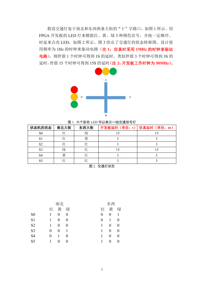
假设交通灯处于南北和东西两条大街的“十”字路口,如图 1 所示。用
FPGA 开发板的 LED 灯来模拟红、黄、绿 3 种颜色信号,并按一定顺序、
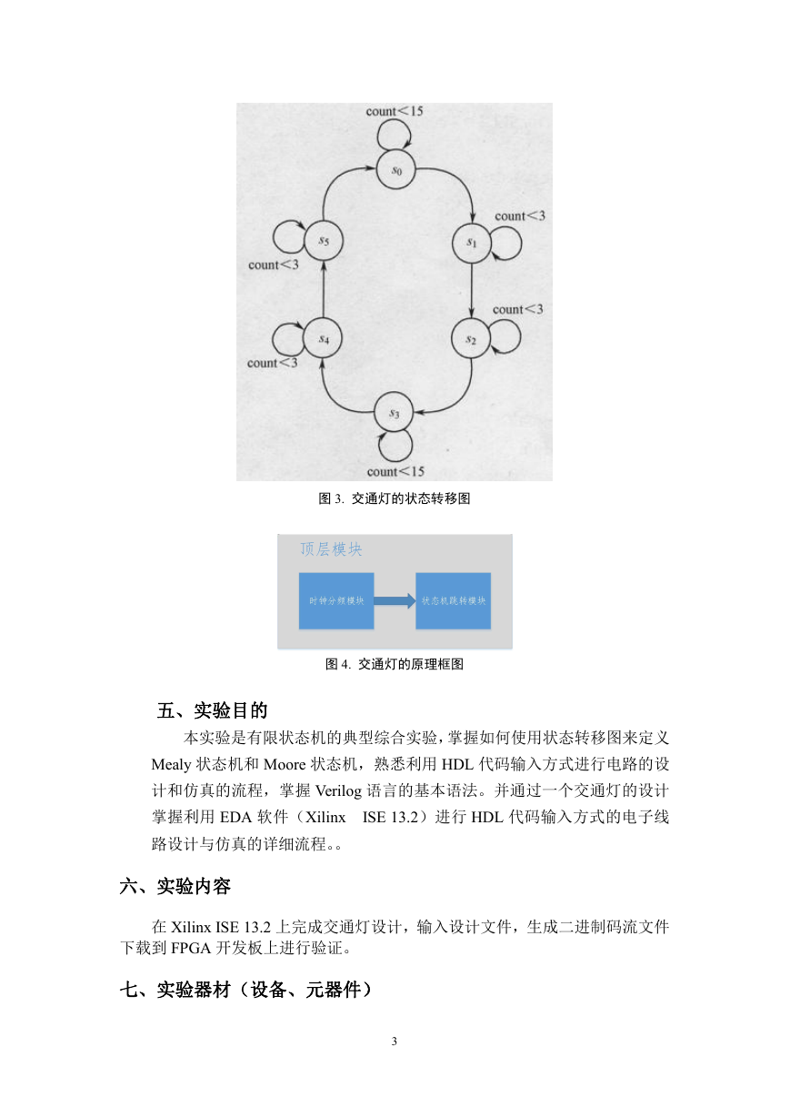
时延来点亮 LED,如图 2 所示。图 3 给出了交通灯的状态转移图。设计使
用频率为 1Hz 的时钟来驱动电路(注 1:仿真时采用 1MHz 的时钟来驱动
电路),则停留 1 个时钟可得到 1S 的延时,类似停留 3 个时钟可得到 3S 的
延时,停留 15 个时钟可得到 15S 的延时(注 2:开发板工作时钟为 50MHz)。
状态机的状态 南北大街
东西大街 开发板延时(单位:s) 仿真延时(单位:us)
图 1. 六个彩色 LED 可以表示一组交通信号灯
S0
S1
S2
S3
S4
S5
红
红
红
绿
黄
红
绿
黄
红
红
红
红
15
3
3
15
3
3
图 2. 交通灯状态
15
3
3
15
3
3
南北
红 黄 绿
1
0
0
1
0
1
0
1
0
0
1
0
0
0
0
0
1
0
S0
S1
S2
S3
S4
S5
东西
红 黄 绿
0
1
0
0
0
1
1
0
0
1
1
0
0
1
0
0
0
0
2
�
图 3. 交通灯的状态转移图
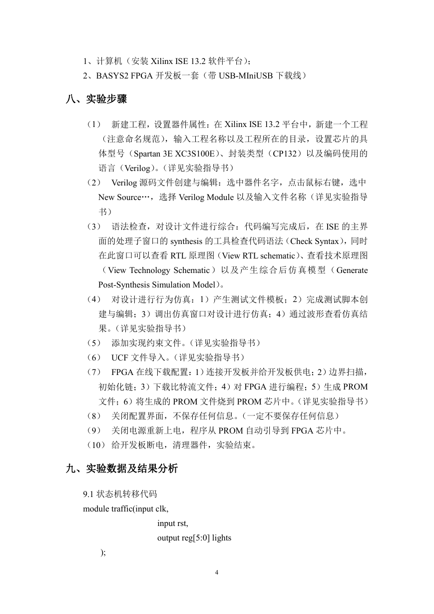
图 4. 交通灯的原理框图
五、实验目的
本实验是有限状态机的典型综合实验,掌握如何使用状态转移图来定义
Mealy 状态机和 Moore 状态机,熟悉利用 HDL 代码输入方式进行电路的设
计和仿真的流程,掌握 Verilog 语言的基本语法。并通过一个交通灯的设计
掌握利用 EDA 软件(Xilinx
ISE 13.2)进行 HDL 代码输入方式的电子线
路设计与仿真的详细流程。。
六、实验内容
在 Xilinx ISE 13.2 上完成交通灯设计,输入设计文件,生成二进制码流文件
下载到 FPGA 开发板上进行验证。
七、实验器材(设备、元器件)
3
�
1、计算机(安装 Xilinx ISE 13.2 软件平台);
2、BASYS2 FPGA 开发板一套(带 USB-MIniUSB 下载线)
八、实验步骤
(1) 新建工程,设置器件属性:在 Xilinx ISE 13.2 平台中,新建一个工程
(注意命名规范),输入工程名称以及工程所在的目录,设置芯片的具
体型号(Spartan 3E XC3S100E)、封装类型(CP132)以及编码使用的
语言(Verilog)。(详见实验指导书)
(2) Verilog 源码文件创建与编辑:选中器件名字,点击鼠标右键,选中
New Source…,选择 Verilog Module 以及输入文件名称(详见实验指导
书)
(3) 语法检查,对设计文件进行综合:代码编写完成后,在 ISE 的主界
面的处理子窗口的 synthesis 的工具检查代码语法(Check Syntax),同时
在此窗口可以查看 RTL 原理图(View RTL schematic)、查看技术原理图
(View Technology Schematic ) 以及 产生 综合 后仿 真模 型(Generate
Post-Synthesis Simulation Model)。
(4) 对设计进行行为仿真:1)产生测试文件模板;2)完成测试脚本创
建与编辑;3)调出仿真窗口对设计进行仿真;4)通过波形查看仿真结
果。(详见实验指导书)
(5) 添加实现约束文件。(详见实验指导书)
(6) UCF 文件导入。(详见实验指导书)
(7) FPGA 在线下载配置:1)连接开发板并给开发板供电;2)边界扫描,
初始化链;3)下载比特流文件;4)对 FPGA 进行编程;5)生成 PROM
文件;6)将生成的 PROM 文件烧到 PROM 芯片中。(详见实验指导书)
(8) 关闭配置界面,不保存任何信息。(一定不要保存任何信息)
(9) 关闭电源重新上电,程序从 PROM 自动引导到 FPGA 芯片中。
(10) 给开发板断电,清理器件,实验结束。
九、实验数据及结果分析
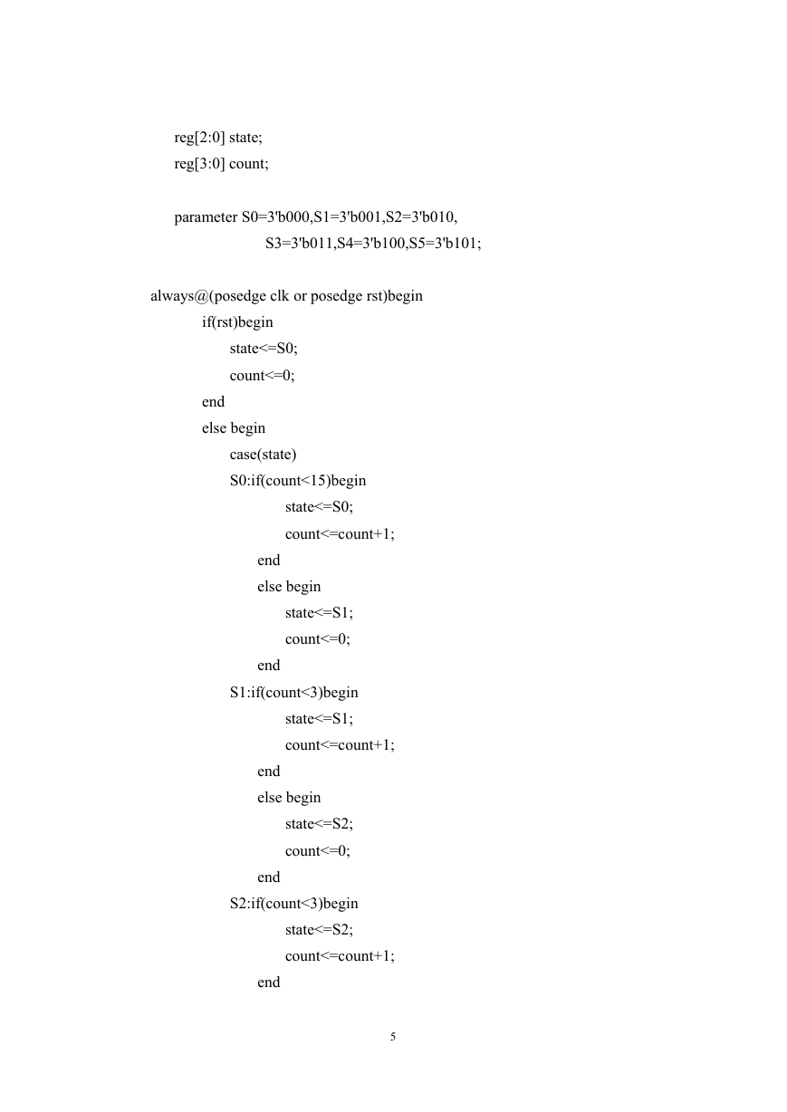
9.1 状态机转移代码
module traffic(input clk,
);
input rst,
output reg[5:0] lights
4
�
reg[2:0] state;
reg[3:0] count;
parameter S0=3'b000,S1=3'b001,S2=3'b010,
S3=3'b011,S4=3'b100,S5=3'b101;
always@(posedge clk or posedge rst)begin
if(rst)begin
state<=S0;
count<=0;
end
else begin
case(state)
S0:if(count<15)begin
state<=S0;
count<=count+1;
end
else begin
state<=S1;
count<=0;
end
S1:if(count<3)begin
state<=S1;
count<=count+1;
end
else begin
state<=S2;
count<=0;
end
S2:if(count<3)begin
state<=S2;
count<=count+1;
end
5
�
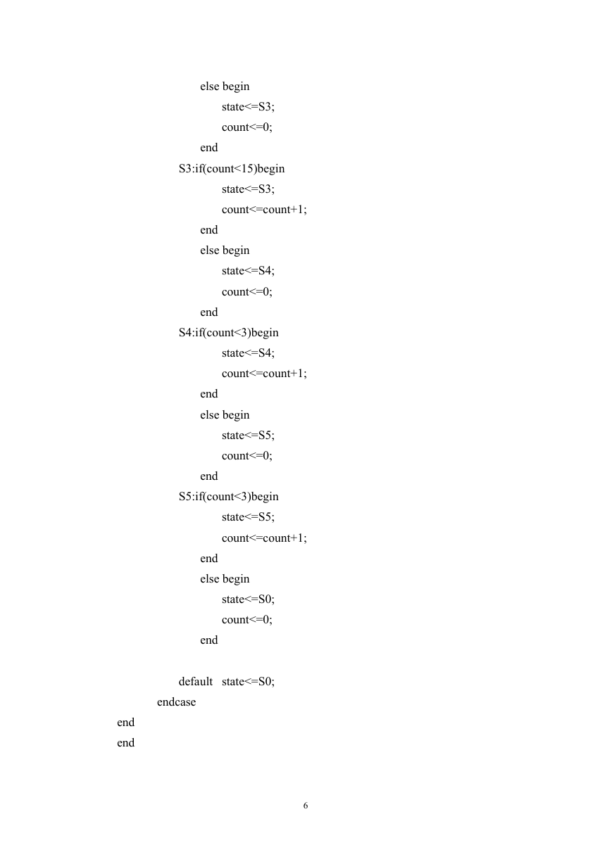
else begin
state<=S3;
count<=0;
end
S3:if(count<15)begin
state<=S3;
count<=count+1;
end
else begin
state<=S4;
count<=0;
end
S4:if(count<3)begin
state<=S4;
count<=count+1;
end
else begin
state<=S5;
count<=0;
end
S5:if(count<3)begin
state<=S5;
count<=count+1;
end
else begin
state<=S0;
count<=0;
end
default state<=S0;
endcase
end
end
6
�
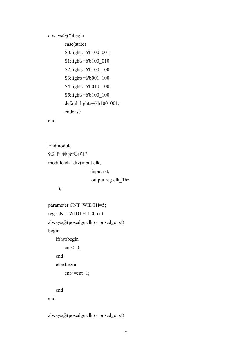
always@(*)begin
case(state)
S0:lights=6'b100_001;
S1:lights=6'b100_010;
S2:lights=6'b100_100;
S3:lights=6'b001_100;
S4:lights=6'b010_100;
S5:lights=6'b100_100;
default lights=6'b100_001;
endcase
end
Endmodule
9.2 时钟分频代码
module clk_div(input clk,
input rst,
output reg clk_1hz
);
parameter CNT_WIDTH=5;
reg[CNT_WIDTH-1:0] cnt;
always@(posedge clk or posedge rst)
begin
if(rst)begin
cnt<=0;
end
else begin
cnt<=cnt+1;
end
end
always@(posedge clk or posedge rst)
7
�
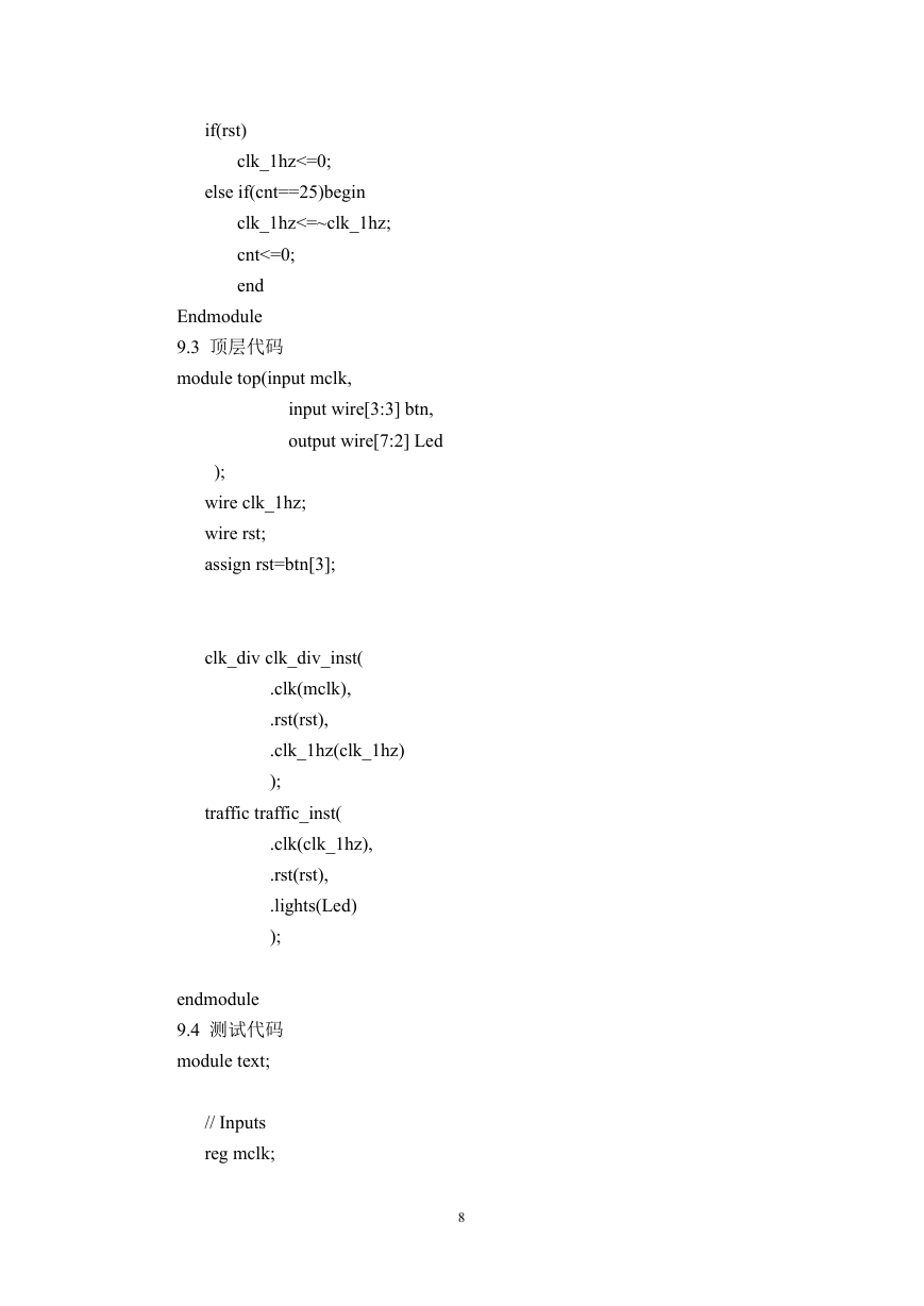
if(rst)
clk_1hz<=0;
else if(cnt==25)begin
clk_1hz<=~clk_1hz;
cnt<=0;
end
Endmodule
9.3 顶层代码
module top(input mclk,
input wire[3:3] btn,
output wire[7:2] Led
);
wire clk_1hz;
wire rst;
assign rst=btn[3];
clk_div clk_div_inst(
.clk(mclk),
.rst(rst),
.clk_1hz(clk_1hz)
);
traffic traffic_inst(
.clk(clk_1hz),
.rst(rst),
.lights(Led)
);
endmodule
9.4 测试代码
module text;
// Inputs
reg mclk;
8
�


 2023年江西萍乡中考道德与法治真题及答案.doc
 2012年重庆南川中考生物真题及答案.doc
 2013年江西师范大学地理学综合及文艺理论基础考研真题.doc
 2020年四川甘孜小升初语文真题及答案I卷.doc
 2020年注册岩土工程师专业基础考试真题及答案.doc
 2023-2024学年福建省厦门市九年级上学期数学月考试题及答案.doc
 2021-2022学年辽宁省沈阳市大东区九年级上学期语文期末试题及答案.doc
 2022-2023学年北京东城区初三第一学期物理期末试卷及答案.doc
 2018上半年江西教师资格初中地理学科知识与教学能力真题及答案.doc
 2012年河北国家公务员申论考试真题及答案-省级.doc
 2020-2021学年江苏省扬州市江都区邵樊片九年级上学期数学第一次质量检测试题及答案.doc
 2022下半年黑龙江教师资格证中学综合素质真题及答案.doc