UM1075
User manual
ST-LINK/V2 in-circuit debugger/programmer for STM8 and STM32
Introduction
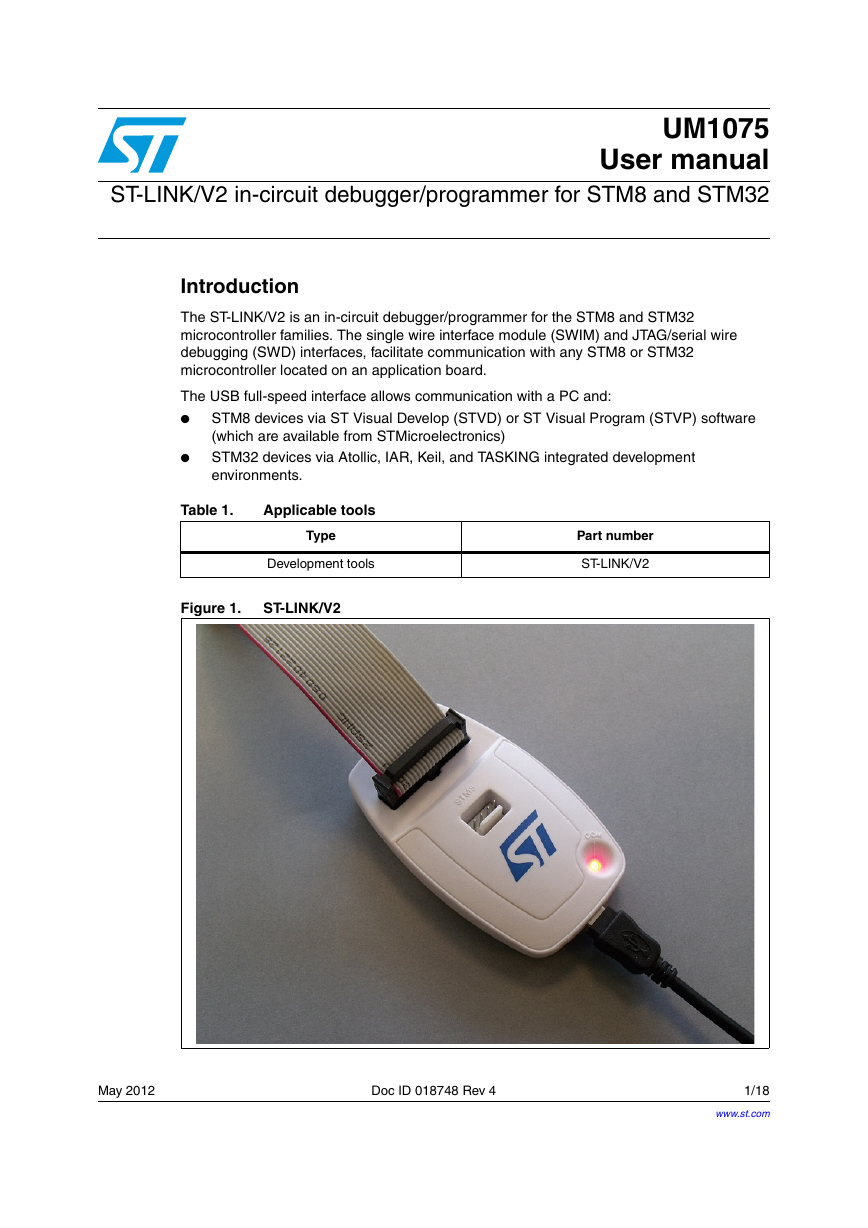
The ST-LINK/V2 is an in-circuit debugger/programmer for the STM8 and STM32
microcontroller families. The single wire interface module (SWIM) and JTAG/serial wire
debugging (SWD) interfaces, facilitate communication with any STM8 or STM32
microcontroller located on an application board.
The USB full-speed interface allows communication with a PC and:
●
STM8 devices via ST Visual Develop (STVD) or ST Visual Program (STVP) software
(which are available from STMicroelectronics)
STM32 devices via Atollic, IAR, Keil, and TASKING integrated development
environments.
●
Table 1.
Applicable tools
Type
Development tools
Figure 1.
ST-LINK/V2
Part number
ST-LINK/V2
May 2012
Doc ID 018748 Rev 4
1/18
www.st.com
�
Contents
Contents
UM1075
1
2
3
4
5
6
Features . . . . . . . . . . . . . . . . . . . . . . . . . . . . . . . . . . . . . . . . . . . . . . . . . . . 5
Product contents . . . . . . . . . . . . . . . . . . . . . . . . . . . . . . . . . . . . . . . . . . . . 6
Hardware configuration . . . . . . . . . . . . . . . . . . . . . . . . . . . . . . . . . . . . . . 7
Connection with STM8 applications . . . . . . . . . . . . . . . . . . . . . . . . . . . . . . 8
3.1
Standard ERNI connection with SWIM flat ribbon . . . . . . . . . . . . . . . . . . 8
3.1.1
Low-cost SWIM connection . . . . . . . . . . . . . . . . . . . . . . . . . . . . . . . . . . . 9
3.1.2
3.1.3
SWIM signals and connections . . . . . . . . . . . . . . . . . . . . . . . . . . . . . . . 10
Connection with STM32 applications . . . . . . . . . . . . . . . . . . . . . . . . . . . . 11
3.2
3.3
ST-LINK/V2 status LEDs . . . . . . . . . . . . . . . . . . . . . . . . . . . . . . . . . . . . . 13
Software configuration . . . . . . . . . . . . . . . . . . . . . . . . . . . . . . . . . . . . . . 14
STM8 application development . . . . . . . . . . . . . . . . . . . . . . . . . . . . . . . . 14
4.1
4.2
STM32 application development and Flash programming . . . . . . . . . . . . 14
Schematics . . . . . . . . . . . . . . . . . . . . . . . . . . . . . . . . . . . . . . . . . . . . . . . 15
Revision history . . . . . . . . . . . . . . . . . . . . . . . . . . . . . . . . . . . . . . . . . . . 17
2/18
Doc ID 018748 Rev 4
�
UM1075
List of tables
List of tables
Table 1.
Table 2.
Table 3.
Table 4.
Table 5.
Applicable tools . . . . . . . . . . . . . . . . . . . . . . . . . . . . . . . . . . . . . . . . . . . . . . . . . . . . . . . . . . . 1
SWIM flat ribbon connections . . . . . . . . . . . . . . . . . . . . . . . . . . . . . . . . . . . . . . . . . . . . . . . 10
JTAG/SWD cable connections . . . . . . . . . . . . . . . . . . . . . . . . . . . . . . . . . . . . . . . . . . . . . . 11
How third party toolchains support ST-LINK/V2 . . . . . . . . . . . . . . . . . . . . . . . . . . . . . . . . . 14
Document revision history . . . . . . . . . . . . . . . . . . . . . . . . . . . . . . . . . . . . . . . . . . . . . . . . . 17
Doc ID 018748 Rev 4
3/18
�
List of figures
List of figures
UM1075
ST-LINK/V2. . . . . . . . . . . . . . . . . . . . . . . . . . . . . . . . . . . . . . . . . . . . . . . . . . . . . . . . . . . . . . 1
Figure 1.
ST-LINK/V2 product contents . . . . . . . . . . . . . . . . . . . . . . . . . . . . . . . . . . . . . . . . . . . . . . . . 6
Figure 2.
Connectors of the ST-LINK/V2 . . . . . . . . . . . . . . . . . . . . . . . . . . . . . . . . . . . . . . . . . . . . . . . 7
Figure 3.
ERNI connection. . . . . . . . . . . . . . . . . . . . . . . . . . . . . . . . . . . . . . . . . . . . . . . . . . . . . . . . . . 8
Figure 4.
Low cost connection . . . . . . . . . . . . . . . . . . . . . . . . . . . . . . . . . . . . . . . . . . . . . . . . . . . . . . . 9
Figure 5.
Target SWIM connector . . . . . . . . . . . . . . . . . . . . . . . . . . . . . . . . . . . . . . . . . . . . . . . . . . . 10
Figure 6.
JTAG and SWD connection . . . . . . . . . . . . . . . . . . . . . . . . . . . . . . . . . . . . . . . . . . . . . . . . 12
Figure 7.
JTAG debugging flat ribbon layout . . . . . . . . . . . . . . . . . . . . . . . . . . . . . . . . . . . . . . . . . . . 12
Figure 8.
Figure 9.
SWIM ST-LINK/V2 standard ERNI cable . . . . . . . . . . . . . . . . . . . . . . . . . . . . . . . . . . . . . . 15
Figure 10. SWIM ST-LINK/V2 low-cost cable . . . . . . . . . . . . . . . . . . . . . . . . . . . . . . . . . . . . . . . . . . . 16
4/18
Doc ID 018748 Rev 4
�
UM1075
1
Features
Features
5 V power supplied by a USB connector
USB 2.0 full speed compatible interface
USB standard A to mini B cable
SWIM specific features
–
–
–
1.65 V to 5.5 V application voltage supported on SWIM interface
SWIM low-speed and high-speed modes supported
SWIM programming speed rate: 9.7 Kbytes/s in low speed and 12.8 Kbytes/s in
high speed
SWIM cable for connection to the application via an ERNI standard vertical (ref:
284697 or 214017) or horizontal (ref: 214012) connector
SWIM cable for connection to the application via a pin header or a 2.54 mm pitch
connector
–
–
●
●
●
●
●
●
JTAG/serial wire debugging (SWD) specific features
–
1.65 V to 3.6 V application voltage supported on the JTAG/SWD interface and 5 V
tolerant inputs
JTAG cable for connection to a standard JTAG 20-pin pitch 2.54 mm connector
Supports JTAG communication
Supports serial wire debug (SWD) and serial wire viewer (SWV) communication
–
–
–
Direct firmware update feature supported (DFU)
Status LED which blinks during communication with the PC
●
● Operating temperature 0 to 50 °C
Doc ID 018748 Rev 4
5/18
�
Product contents
UM1075
2
Product contents
Figure 2: ST-LINK/V2 product contents shows the various cables delivered within the
product. They include (from left to right in Figure 2):
●
USB standard A to mini B cable (A)
ST-LINK/V2 debugging and programming (B)
SWIM flat ribbon ended with a 4-pin, 2.54 mm, low-cost connector on two sides (C)
SWIM flat ribbon with a standard ERNI connector at one end and 4-pin connector at the
other end (D)
JTAG or SWD and SWV flat ribbon with a 20-pin connector at one end (E)
●
●
●
●
Figure 2.
ST-LINK/V2 product contents
B
C
D
E
A
6/18
Doc ID 018748 Rev 4
�
UM1075
Hardware configuration
3
Hardware configuration
The ST-LINK/V2 is designed around the STM32F103C8 device which incorporates the high-
performance ARM®, Cortex™-M3 core. It is available in a TQFP48 package.
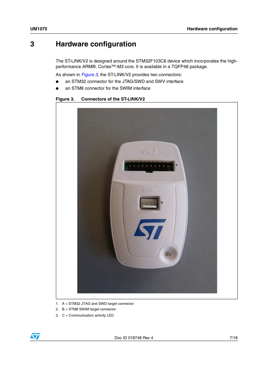
As shown in Figure 3, the ST-LINK/V2 provides two connectors:
an STM32 connector for the JTAG/SWD and SWV interface
●
an STM8 connector for the SWIM interface
●
Figure 3.
Connectors of the ST-LINK/V2
A
B
C
1. A = STM32 JTAG and SWD target connector
2. B = STM8 SWIM target connector
3. C = Communication activity LED
Doc ID 018748 Rev 4
7/18
�
Hardware configuration
UM1075
3.1
Connection with STM8 applications
For STM8 developments, the ST-LINK/V2 can be connected to the target board by two
different cables, depending on the connector available on the application board.
These cables are:
●
SWIM flat ribbon with a standard ERNI connector at one end and a 4-pin connector at
the other end
SWIM cable with two 4-pin, 2.54 mm connectors
●
3.1.1
Standard ERNI connection with SWIM flat ribbon
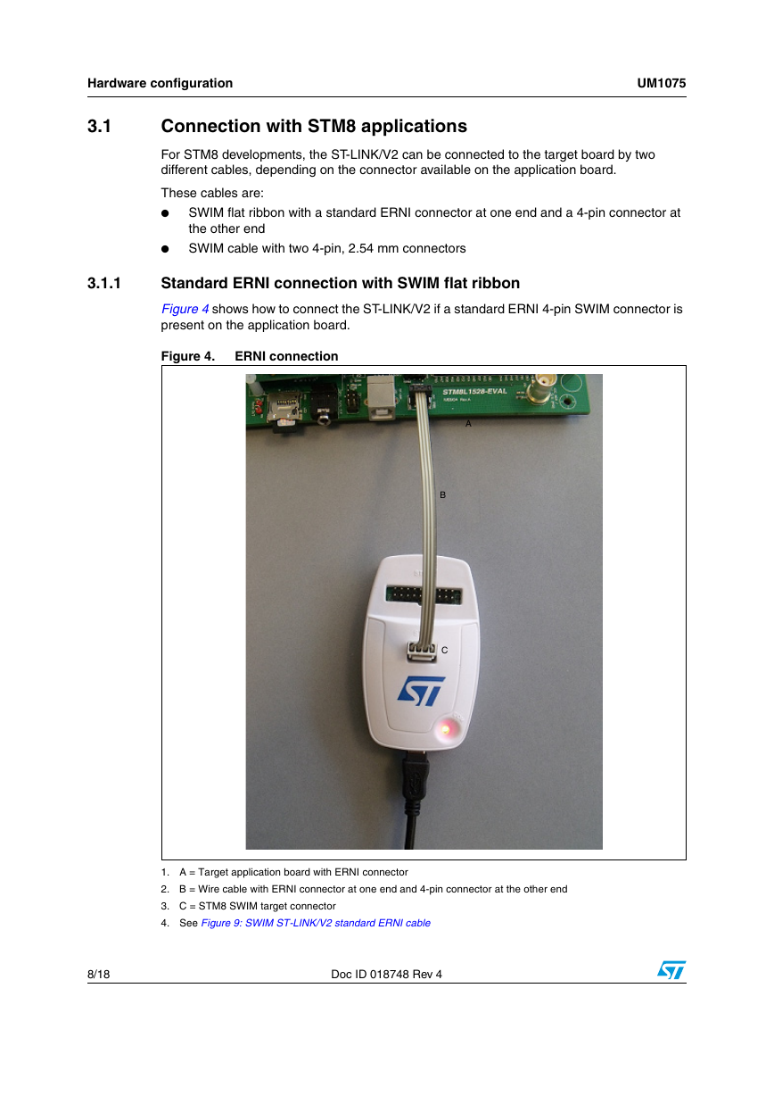
Figure 4 shows how to connect the ST-LINK/V2 if a standard ERNI 4-pin SWIM connector is
present on the application board.
Figure 4.
ERNI connection
A
B
C
1. A = Target application board with ERNI connector
2. B = Wire cable with ERNI connector at one end and 4-pin connector at the other end
3. C = STM8 SWIM target connector
4. See Figure 9: SWIM ST-LINK/V2 standard ERNI cable
8/18
Doc ID 018748 Rev 4
�



 2023年江西萍乡中考道德与法治真题及答案.doc
 2012年重庆南川中考生物真题及答案.doc
 2013年江西师范大学地理学综合及文艺理论基础考研真题.doc
 2020年四川甘孜小升初语文真题及答案I卷.doc
 2020年注册岩土工程师专业基础考试真题及答案.doc
 2023-2024学年福建省厦门市九年级上学期数学月考试题及答案.doc
 2021-2022学年辽宁省沈阳市大东区九年级上学期语文期末试题及答案.doc
 2022-2023学年北京东城区初三第一学期物理期末试卷及答案.doc
 2018上半年江西教师资格初中地理学科知识与教学能力真题及答案.doc
 2012年河北国家公务员申论考试真题及答案-省级.doc
 2020-2021学年江苏省扬州市江都区邵樊片九年级上学期数学第一次质量检测试题及答案.doc
 2022下半年黑龙江教师资格证中学综合素质真题及答案.doc