logo资料库

CISPR 25--2008.pdf

第1页 / 共172页
第2页 / 共172页
第3页 / 共172页
第4页 / 共172页
第5页 / 共172页
第6页 / 共172页
第7页 / 共172页
第8页 / 共172页
资料共172页,剩余部分请下载后查看
English
CONTENTS
FOREWORD
INTRODUCTION
1 Scope
2 Normative references
3 Terms and definitions
4 Requirements common to vehicle and component/module emissions measurement
4.1 General test requirements and test plan
4.2 Shielded enclosure
4.3 Absorber-lined shielded enclosure (ALSE)
4.4 Measuring instrument
4.5 Power supply
5 Measurement of emissions received by an antenna on the same vehicle
5.1 Antenna measuring system
5.2 Method of measurement
5.3 Examples of limits for vehicle radiated disturbances
6 Measurement of components and modules
6.1 Test equipment
6.2 Conducted emissions from components/modules – Voltage method
6.3 Conducted emissions from components/modules – current probe method
6.4 Radiated emissions from components/modules – ALSE method
6.5 Radiated emissions from components/modules – TEM cell method
6.6 Radiated emissions from components/modules – Stripline method
Annex A (informative) Flow chart for checking the applicability of CISPR 25
Annex B (normative) Antenna matching unit – Vehicle test
Annex C (informative) Sheath-current suppressor
Annex D (informative) Guidance for the determination of the noise floor of active vehicle antennas in the AM and FM range
Annex E (normative) Artificial network
Annex F (informative) TEM cell dimensions
Annex G (informative) Radiated emissions from components/modules – Stripline method
Annex H (informative) Interference to mobile radio communication in the presence of impulsive noise – Methods of judging degradation
Annex I (informative) Items under consideration
Bibliography
Figures
Figure 1 – Method of determination of conformance for all frequency bands
Figure 2 – Example of gain curve
Figure 3 – Vehicle-radiated emissions – Example for test layout (end view with monopole antenna)
Figure 4 – Average limit for radiated disturbances from vehicles GPS band 1 567,42 to 1 583,42 MHz
Figure 5 – Example for the required minimum attenuation of the signal / control line filters
Figure 6 – Conducted emissions – EUT with power return line remotely grounded.
Figure 7 – Conducted emissions – EUT with power return line locally grounded
Figure 8 – Conducted emissions – Test layout for alternators and generators
Figure 9 – Conducted emissions – Test layout for ignition system components
Figure 10 – Conducted emissions – Example of test layout for current probe measurements
Figure 11 – Test harness bending requirements
Figure 12 – Example of test set-up – rod antenna
Figure 13 – Example of test set-up – biconical antenna
Figure 14 – Example of test set-up – log-periodic antenna
Figure 15 – Example of test set-up – above 1 GHz
Figure 16 – Example of average limit for radiated disturbances from components GPS band 1 567,42 to 1 583,42 MHz – Class 5
Figure 17 – TEM cell
Figure 18 – Example of arrangement of leads in the TEM cell and to the connector panel
Figure 19 – Example of the arrangement of the connectors, the lead frame and the dielectric support
Figure 20 – Example of the TEM cell method test layout
Figure B.1 –Verification set-up
Figure C.1 – Attenuation vs. frequency
Figure D.1 – Vehicle test set up for equipment noise measurement in the AM/FM range
Figure D.2 – Vehicle test set up for antenna noise measurement in the AM/FM range
Figure E.1 – Characteristics of the AN impedance
Figure E.2 – Example of 5 μH AN schematic
Figure F.1 – TEM cell
Figure G.1 – Example of a basic stripline test setup in a shielded enclosure
Figure G.2 – Example for a 50 Ω stripline
Figure G.3 – Example for a 90 Ω stripline
Tables
Table 1 – Spectrum analyser parameters
Table 2 – Scanning receiver parameters
Table 3 – Antenna types
Table 4 – Example for limits of disturbance – Complete vehicle
Table 5 – Examples of quasi-peak or peak limits for conducted disturbances – Voltage method
Table 6 – Examples of average limits for conducted disturbances – Voltage method
Table 7 – Examples of quasi-peak and peak limits for conducted disturbances – Control/signal lines – Current probe method
Table 8 – Examples of average limits for conducted disturbances – Control/signal lines – Current probe method
Table 9 – Examples of quasi-peak or peak limits for radiated disturbances – ALSE
Table 10 – Examples of average limits for radiated disturbances – ALSE
Table 11 – Examples of quasi-peak or peak limits for radiated disturbances – TEM cell
Table 12 – Examples of average limits for radiated disturbances – TEM cell
Table F.1 – Dimensions for TEM cells
Table G.1 – Examples of quasi-peak or peak limits for radiated disturbances – Stripline
Table G.2 – Examples of average limits for radiated disturbances – Stripline
Français
SOMMAIRE
AVANT-PROPOS
INTRODUCTION
1 Domaine d’application
2 Références normatives
3 Termes et définitions
4 Exigences communes pour les mesures de perturbations sur les véhicules et sur les équipements/modules
4.1 Exigences générales d’essai et plan d'essai
4.2 Cage de Faraday
4.3 Cage de Faraday recouverte d'absorbants (chambre anéchoïque)
4.4 Instrument de mesure
4.5 Alimentation
5 Mesure des perturbations reçues par une antenne située sur le même véhicule
5.1 Système d'antenne de mesure
5.2 Méthode de mesure
5.3 Exemples de limites des perturbations rayonnées sur véhicules
6 Mesures sur équipements et modules
6.1 Matériel d'essai
6.2 Émissions conduites par les équipements/modules – Méthode en tension
6.3 Émissions conduites par les équipements/modules – méthode de la pince de courant
6.4 Émissions rayonnées des composants/modules – Méthode de la chambre anéchoïque
6.5 Émissions rayonnées des composants/modules – Méthode de la cellule TEM
6.6 Émissions rayonnées des composants/modules – Méthode de la ligne TEM à plaques
Annexe A (informative) Diagramme d'application de la CISPR 25
Annexe B (normative) Système d'adaptation d'antenne – Essai véhicule
Annexe C (informative) Suppresseur de courant de surface
Annexe D (informative) Indications pour la détermination du niveau de bruit des antennes de véhicules actives dans les bandes de fréquences MA et MF
Annexe E (normative) Réseau fictif
Annexe F (informative) Dimensions des cellules TEM
Annexe G (informative) Émissions rayonnées des composants/modules – Méthode de la ligne TEM à plaques
Annexe H (informative) Interférences nocives aux communications radio liées au bruit impulsif – Méthodes d'évaluation de la dégradation des communications
Annexe I (informative) Travaux à l’étude
Bibliographie
Figures
Figure 1 – Méthode pour déterminer la conformité de l’ensemble des bandes de fréquences
Figure 2 – Exemple de courbe de gain
Figure 3 – Émissions rayonnées sur véhicules – Exemple de schéma d'essai (vue de face avec une antenne de type monopole)
Figure 4 – Limite valeur moyenne sur véhicule, pour les perturbations rayonnées dans la bande GPS 1 567,42 à 1 583,42 MHz
Figure 5 – Exemple pour l'atténuation minimale requise d'un filtre de ligne signal / contrôle
Figure 6 – Émissions conduites – Appareil en essai avec ligne de retour d'alimentation raccordée au châssis à distance
Figure 7 – Émissions conduites – Appareil en essai avec ligne de retour d'alimentation raccordée au châssis localement
Figure 8 – Émissions conduites – Montage d'essai pour alternateurs et générateurs
Figure 9 – Émissions conduites – Montage d'essai pour les composants du système d'allumage
Figure 10 – Émissions conduites – Exemple de schéma d'essai pour les mesures avec pince de courant
Figure 11 – Exigences relatives à la déviation du faisceau d'essai
Figure 12 – Exemple de montage d'essai – antenne fouet
Figure 13 – Exemple de montage d'essai – antenne biconique
Figure 14 – Exemple de montage d'essai – antenne log-périodique
Figure 15 – Exemple de montage d'essai – fréquences supérieures à 1 GHz
Figure 16 – Exemple de limite valeur moyenne pour les émissions rayonnées des composants sur la bande GPS allant de 1 567,42 MHz à 1 583,42 MHz – Classe 5
Figure 17 – Cellule TEM
Figure 18 – Exemple de disposition des fils dans la cellule TEM et du raccordement au panneau de connecteurs
Figure 19 – Exemple de disposition des connecteurs, du circuit en nappe et du support diélectrique
Figure 20 – Exemple de schéma d'essai pour la méthode de la cellule TEM
Figure B.1 – Montage utilisé pour la vérification
Figure C.1 – Atténuation en fonction de la fréquence
Figure D.1 – Configuration du véhicule utilisée pour les essais de mesure du niveau de bruit des équipements dans les bandes de fréquences MA et MF
Figure D.2 – Configuration du véhicule utilisée pour les mesures du niveau de bruit de l’antenne dans les bandes de fréquences MA et MF
Figure E.1 – Caractéristiques d'impédance du réseau fictif
Figure E.2 – Exemple de schéma de réseau fictif 5 μH
Figure F.1 – Cellule TEM
Figure G.1 – Exemple de montage d'essai de base d'une ligne TEM à plaques dans une enceinte blindée
Figure G.2 – Exemple pour une ligne TEM à plaques d'impédance caractéristique de 50 Ω
Figure G.3 – Exemple pour une ligne TEM à plaques d'impédance caractéristique de 90 Ω
Tableaux
Tableau 1 – Paramètres de l’analyseur de spectre
Tableau 2 – Paramètres du récepteur à balayage
Tableau 3 – Types d'antennes
Tableau 4 – Exemples de limites de perturbations – Véhicule complet
Tableau 5 – Exemples de limites quasi-crête ou crête pour les perturbations conduites – Méthode en tension
Tableau 6 – Exemples de limites valeur moyenne (AVG) pour les perturbations conduites – Méthode en tension
Tableau 7 – Exemples de limites quasi-crête et crête pour les perturbations conduites – Fils de contrôle/signaux – Méthode de la pince de courant
Tableau 8 – Exemples de limites valeur moyenne (AVG) pour les perturbations conduites – Fils de contrôle/signaux – Méthode de la pince de courant
Tableau 9 – Exemples de limites quasi-crête ou crête pour les perturbations rayonnées – Méthode de la chambre anéchoïque
Tableau 10 – Exemples de limites valeur moyenne (AVG) pour les perturbations rayonnées – Méthode de la chambre anéchoïque
Tableau 11 – Exemples de limites quasi-crête ou crête pour les perturbations rayonnées – Méthode de la cellule TEM
Tableau 12 – Exemples de limites valeur moyenne (AVG) pour les perturbations rayonnées – Méthode de la cellule TEM
Tableau F.1 – Dimensions des cellules TEM
Tableau G.1 – Exemples de limites quasi-crête ou crête pour les perturbations rayonnées – Méthode de la ligne TEM à plaques
Tableau G.2 – Exemples de limites valeur moyenne (AVG) pour les perturbations rayonnées – Méthode de la ligne TEM à plaques
CISPR 25 Edition 3.0 2008-03 INTERNATIONAL STANDARD NORME INTERNATIONALE INTERNATIONAL SPECIAL COMMITTEE ON RADIO INTERFERENCE COMITÉ INTERNATIONAL SPÉCIAL DES PERTURBATIONS RADIOÉLECTRIQUES Vehicles, boats and internal combustion engines – Radio disturbance characteristics – Limits and methods of measurement for the protection of on-board receivers Véhicules, bateaux et moteurs à combustion interne – Caractéristiques des perturbations radioélectriques – Limites et méthodes de mesure pour la protection des récepteurs embarqués 8 0 0 2 : 5 2 R P S C I
THIS PUBLICATION IS COPYRIGHT PROTECTED Copyright © 2008 IEC, Geneva, Switzerland All rights reserved. Unless otherwise specified, no part of this publication may be reproduced or utilized in any form or by any means, electronic or mechanical, including photocopying and microfilm, without permission in writing from either IEC or IEC's member National Committee in the country of the requester. If you have any questions about IEC copyright or have an enquiry about obtaining additional rights to this publication, please contact the address below or your local IEC member National Committee for further information. Droits de reproduction réservés. Sauf indication contraire, aucune partie de cette publication ne peut être reproduite ni utilisée sous quelque forme que ce soit et par aucun procédé, électronique ou mécanique, y compris la photocopie et les microfilms, sans l'accord écrit de la CEI ou du Comité national de la CEI du pays du demandeur. Si vous avez des questions sur le copyright de la CEI ou si vous désirez obtenir des droits supplémentaires sur cette publication, utilisez les coordonnées ci-après ou contactez le Comité national de la CEI de votre pays de résidence. IEC Central Office 3, rue de Varembé CH-1211 Geneva 20 Switzerland Email: inmail@iec.ch Web: www.iec.ch About the IEC The International Electrotechnical Commission (IEC) is the leading global organization that prepares and publishes International Standards for all electrical, electronic and related technologies. About IEC publications The technical content of IEC publications is kept under constant review by the IEC. Please make sure that you have the latest edition, a corrigenda or an amendment might have been published. Catalogue of IEC publications: www.iec.ch/searchpub The IEC on-line Catalogue enables you to search by a variety of criteria (reference number, text, technical committee,…). It also gives information on projects, withdrawn and replaced publications. IEC Just Published: www.iec.ch/online_news/justpub Stay up to date on all new IEC publications. Just Published details twice a month all new publications released. Available on-line and also by email. Electropedia: www.electropedia.org The world's leading online dictionary of electronic and electrical terms containing more than 20 000 terms and definitions in English and French, with equivalent terms in additional languages. Also known as the International Electrotechnical Vocabulary online. Customer Service Centre: www.iec.ch/webstore/custserv If you wish to give us your feedback on this publication or need further assistance, please visit the Customer Service Centre FAQ or contact us: Email: csc@iec.ch Tel.: +41 22 919 02 11 Fax: +41 22 919 03 00 A propos de la CEI La Commission Electrotechnique Internationale (CEI) est la première organisation mondiale qui élabore et publie des normes internationales pour tout ce qui a trait à l'électricité, à l'électronique et aux technologies apparentées. A propos des publications CEI Le contenu technique des publications de la CEI est constamment revu. Veuillez vous assurer que vous possédez l’édition la plus récente, un corrigendum ou amendement peut avoir été publié. Catalogue des publications de la CEI: www.iec.ch/searchpub/cur_fut-f.htm Le Catalogue en-ligne de la CEI vous permet d’effectuer des recherches en utilisant différents critères (numéro de référence, texte, comité d’études,…). Il donne aussi des informations sur les projets et les publications retirées ou remplacées. Just Published CEI: www.iec.ch/online_news/justpub Restez informé sur les nouvelles publications de la CEI. Just Published détaille deux fois par mois les nouvelles publications parues. Disponible en-ligne et aussi par email. Electropedia: www.electropedia.org Le premier dictionnaire en ligne au monde de termes électroniques et électriques. Il contient plus de 20 000 termes et définitions en anglais et en français, ainsi que les termes équivalents dans les langues additionnelles. Egalement appelé Vocabulaire Electrotechnique International en ligne. Service Clients: www.iec.ch/webstore/custserv/custserv_entry-f.htm Si vous désirez nous donner des commentaires sur cette publication ou si vous avez des questions, visitez le FAQ du Service clients ou contactez-nous: Email: csc@iec.ch Tél.: +41 22 919 02 11 Fax: +41 22 919 03 00
INTERNATIONAL STANDARD NORME INTERNATIONALE CISPR 25 Edition 3.0 2008-03 INTERNATIONAL SPECIAL COMMITTEE ON RADIO INTERFERENCE COMITÉ INTERNATIONAL SPÉCIAL DES PERTURBATIONS RADIOÉLECTRIQUES Vehicles, boats and internal combustion engines – Radio disturbance characteristics – Limits and methods of measurement for the protection of on-board receivers Véhicules, bateaux et moteurs à combustion interne – Caractéristiques des perturbations radioélectriques – Limites et méthodes de mesure pour la protection des récepteurs embarqués INTERNATIONAL ELECTROTECHNICAL COMMISSION COMMISSION ELECTROTECHNIQUE INTERNATIONALE ICS 33.100.10; 33.100.20 PRICE CODE CODE PRIX XC ISBN 2-8318-9664-9
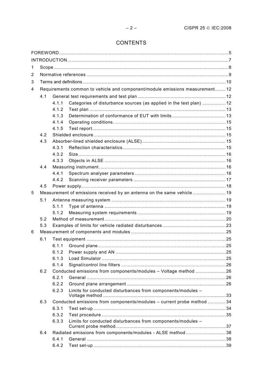
– 2 – CISPR 25 © IEC:2008 CONTENTS FOREWORD...........................................................................................................................5 INTRODUCTION.....................................................................................................................7 1 Scope...............................................................................................................................8 2 Normative references .......................................................................................................9 3 Terms and definitions........................................................................................................10 4 Requirements common to vehicle and component/module emissions measurement........ 12 4.1 General test requirements and test plan ................................................................12 4.1.1 Categories of disturbance sources (as applied in the test plan) ................. 12 4.1.2 Test plan ...................................................................................................13 4.1.3 Determination of conformance of EUT with limits .......................................13 4.1.4 Operating conditions..................................................................................15 4.1.5 Test report.................................................................................................15 4.2 Shielded enclosure................................................................................................15 4.3 Absorber-lined shielded enclosure (ALSE).............................................................15 4.3.1 Reflection characteristics...........................................................................15 4.3.2 Size...........................................................................................................16 4.3.3 Objects in ALSE ........................................................................................16 4.4 Measuring instrument ............................................................................................16 4.4.1 Spectrum analyser parameters ..................................................................16 4.4.2 Scanning receiver parameters ...................................................................17 4.5 Power supply.........................................................................................................18 5 Measurement of emissions received by an antenna on the same vehicle ........................ 19 5.1 Antenna measuring system ...................................................................................19 5.1.1 Type of antenna ........................................................................................19 5.1.2 Measuring system requirements ................................................................19 5.2 Method of measurement ........................................................................................20 5.3 Examples of limits for vehicle radiated disturbances ..............................................23 6 Measurement of components and modules .....................................................................25 6.1 Test equipment .....................................................................................................25 6.1.1 Ground plane.............................................................................................25 6.1.2 Power supply and AN ................................................................................25 6.1.3 Load Simulator ..........................................................................................25 6.1.4 Signal/control line filters ............................................................................26 6.2 Conducted emissions from components/modules – Voltage method ......................26 6.2.1 General .....................................................................................................26 6.2.2 Ground plane arrangement ........................................................................26 6.2.3 Limits for conducted disturbances from components/modules – Voltage method .........................................................................................33 6.3 Conducted emissions from components/modules – current probe method ............. 34 6.3.1 Test set-up ................................................................................................34 6.3.2 Test procedure ..........................................................................................35 6.3.3 Limits for conducted disturbances from components/modules – Current probe method................................................................................37 6.4 Radiated emissions from components/modules - ALSE method ............................. 38 6.4.1 General .....................................................................................................38 6.4.2 Test set-up ................................................................................................39
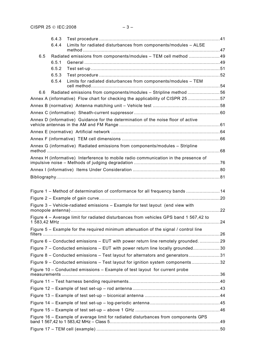
CISPR 25 © IEC:2008 – 3 – 6.4.3 Test procedure ..........................................................................................41 6.4.4 Limits for radiated disturbances from components/modules – ALSE method ......................................................................................................47 6.5 Radiated emissions from components/modules – TEM cell method ....................... 49 6.5.1 General .....................................................................................................49 6.5.2 Test set-up ................................................................................................51 6.5.3 Test procedure ..........................................................................................52 6.5.4 Limits for radiated disturbances from components/modules – TEM cell method................................................................................................54 6.6 Radiated emissions from components/modules – Stripline method ........................ 56 Annex A (informative) Flow chart for checking the applicability of CISPR 25 ........................57 Annex B (normative) Antenna matching unit – Vehicle test ..................................................58 Annex C (informative) Sheath-current suppressor ................................................................60 Annex D (informative) Guidance for the determination of the noise floor of active vehicle antennas in the AM and FM Range ...........................................................................61 Annex E (normative) Artificial network .................................................................................64 Annex F (informative) TEM cell dimensions .........................................................................66 Annex G (informative) Radiated emissions from components/modules – Stripline method .................................................................................................................................68 Annex H (informative) Interference to mobile radio communication in the presence of impulsive noise – Methods of judging degradation ................................................................76 Annex I (informative) Items Under Consideration .................................................................80 Bibliography..........................................................................................................................81 Figure 1 – Method of determination of conformance for all frequency bands ......................... 14 Figure 2 – Example of gain curve..........................................................................................20 Figure 3 – Vehicle-radiated emissions – Example for test layout (end view with monopole antenna) ...............................................................................................................22 Figure 4 – Average limit for radiated disturbances from vehicles GPS band 1 567,42 to 1 583,42 MHz .......................................................................................................................24 Figure 5 – Example for the required minimum attenuation of the signal / control line filters ....................................................................................................................................26 Figure 6 – Conducted emissions – EUT with power return line remotely grounded. ............... 29 Figure 7 – Conducted emissions – EUT with power return line locally grounded.................... 30 Figure 8 – Conducted emissions – Test layout for alternators and generators ....................... 31 Figure 9 – Conducted emissions – Test layout for ignition system components .....................32 Figure 10 – Conducted emissions – Example of test layout for current probe measurements ......................................................................................................................36 Figure 11 – Test harness bending requirements....................................................................40 Figure 12 – Example of test set-up – rod antenna .................................................................43 Figure 13 – Example of test set-up – biconical antenna ........................................................44 Figure 14 – Example of test set-up – log-periodic antenna .................................................... 45 Figure 15 – Example of test set-up – above 1 GHz ...............................................................46 Figure 16 – Example of average limit for radiated disturbances from components GPS band 1 567,42 to 1 583,42 MHz – Class 5..................................................................................49 Figure 17 – TEM cell (example) ............................................................................................50
– 4 – CISPR 25 © IEC:2008 Figure 18 – Example of arrangement of leads in the TEM cell and to the connector panel ....................................................................................................................................51 Figure 19 – Example of the arrangement of the connectors, the lead frame and the dielectric support ..................................................................................................................52 Figure 20 – Example of the TEM cell method test layout .......................................................53 Figure B.1 –Verification set-up..............................................................................................59 Figure C.1 – Attenuation vs. frequency .................................................................................60 Figure D.1 – Vehicle test set up for equipment noise measurement in the AM/FM range .......62 Figure D.2 – Vehicle test set up for antenna noise measurement in the AM/FM range........... 63 Figure E.1 – Characteristics of the AN impedance ................................................................ 64 Figure E.2 – Example of 5 μH AN schematic.........................................................................65 Figure F.1 – TEM cell ...........................................................................................................66 Figure G.1 – Example of a basic stripline test setup in a shielded enclosure ......................... 70 Figure G.2 – Example for a 50 Ω stripline .............................................................................74 Figure G.3 – Example for a 90 Ω stripline .............................................................................75 Table 1 – Spectrum analyser parameters ..............................................................................17 Table 2 – Scanning receiver parameters ...............................................................................18 Table 3 – Antenna types .......................................................................................................19 Table 4 – Example for limits of disturbance – Complete vehicle ............................................23 Table 5 – Examples of quasi-peak or peak limits for conducted disturbances – Voltage Method .................................................................................................................................33 Table 6 – Examples of average limits for conducted disturbances – Voltage Method............. 34 Table 7 – Examples of quasi-peak and peak limits for conducted disturbances - control/signal lines – Current probe method ..........................................................................37 Table 8 – Examples of average limits for conducted disturbances - control/signal lines – Current probe method ........................................................................................................38 Table 9 – Examples of quasi-peak or peak limits for radiated disturbances – ALSE .............. 47 Table 10 – Examples of average limits for radiated disturbances – ALSE.............................. 48 Table 11 – Examples of quasi-peak or peak limits for radiated disturbances – TEM cell........ 55 Table 12 – Examples of average limits for radiated disturbances – TEM Cell ........................ 56 Table F.1 – Dimensions for TEM cells...................................................................................67 Table G.1 – Examples of quasi-peak or peak limits for radiated disturbances – Stripline ................................................................................................................................71 Table G.2 – Examples of average limits for radiated disturbances – Stripline ........................ 72
CISPR 25 © IEC:2008 – 5 – INTERNATIONAL ELECTROTECHNICAL COMMISSION INTERNATIONAL SPECIAL COMMITTEE ON RADIO INTERFERENCE VEHICLES, BOATS AND INTERNAL COMBUSTION ENGINES – RADIO DISTURBANCE CHARACTERISTICS – LIMITS AND METHODS OF MEASUREMENT FOR THE PROTECTION OF ON-BOARD RECEIVERS ____________ FOREWORD 1) The International Electrotechnical Commission (IEC) is a worldwide organization for standardization comprising all national electrotechnical committees (IEC National Committees). The object of IEC is to promote international co-operation on all questions concerning standardization in the electrical and electronic fields. To this end and in addition to other activities, IEC publishes International Standards, Technical Specifications, Technical Reports, Publicly Available Specifications (PAS) and Guides (hereafter referred to as “IEC Publication(s)”). Their preparation is entrusted to technical committees; any IEC National Committee interested in the subject dealt with may participate in this preparatory work. International, governmental and non- governmental organizations liaising with the IEC also participate in this preparation. IEC collaborates closely with the International Organization for Standardization (ISO) in accordance with conditions determined by agreement between the two organizations. 2) The formal decisions or agreements of IEC on technical matters express, as nearly as possible, an international consensus of opinion on the relevant subjects since each technical committee has representation from all interested IEC National Committees. 3) IEC Publications have the form of recommendations for international use and are accepted by IEC National Committees in that sense. While all reasonable efforts are made to ensure that the technical content of IEC Publications is accurate, IEC cannot be held responsible for the way in which they are used or for any misinterpretation by any end user. 4) In order to promote international uniformity, IEC National Committees undertake to apply IEC Publications transparently to the maximum extent possible in their national and regional publications. Any divergence between any IEC Publication and the corresponding national or regional publication shall be clearly indicated in the latter. 5) IEC provides no marking procedure to indicate its approval and cannot be rendered responsible for any equipment declared to be in conformity with an IEC Publication. 6) All users should ensure that they have the latest edition of this publication. 7) No liability shall attach to IEC or its directors, employees, servants or agents including individual experts and members of its technical committees and IEC National Committees for any personal injury, property damage or other damage of any nature whatsoever, whether direct or indirect, or for costs (including legal fees) and expenses arising out of the publication, use of, or reliance upon, this IEC Publication or any other IEC Publications. 8) Attention is drawn to the Normative references cited in this publication. Use of the referenced publications is indispensable for the correct application of this publication. 9) Attention is drawn to the possibility that some of the elements of this IEC Publication may be the subject of patent rights. IEC shall not be held responsible for identifying any or all such patent rights. International Standard CISPR 25 has been prepared by CISPR subcommittee D: Electromagnetic disturbances related to electric/electronic equipment on vehicles and internal combustion engine powered devices. This third edition cancels and replaces the second edition published in 2002. This edition constitutes a technical revision. The following significant changes were made with respect to the previous edition: – addition of required measurements with both an average detector and a peak or quasi- peak detector; – addition of methods and limits for the protection of new analogue and digital radio services, which cover the frequency range up to 2 500 MHz; – addition of a new measurement method for components (stripline) as an informative Annex G;
– 6 – CISPR 25 © IEC:2008 – addition of the contents of CISPR 21 as Annex H; CISPR 21 in its entirety now becomes obsolete. – deletion of narrowband / broadband determination; – deletion of the Annex on rod antenna characterisation (this CISPR 16-1-4); is now covered by – deletion of the Annex on characterisation of shielded enclosure (CISPR 25 will be amended when the CISPR/D / CISPR/A Joint Task Force on chamber validation finishes its work). The text of this standard is based on the following documents: Enquiry draft CISPR/D/344/CDV Report on voting CISPR/D/352/RVC Full information on the voting for the approval of this standard can be found in the report on voting indicated in the above Table. This publication has been drafted in accordance with the ISO/IEC Directives, Part 2. The committee has decided that the contents of this publication will remain unchanged until the maintenance result date indicated on the IEC web site under "http://webstore.iec.ch" in the data related to the specific publication. At this date, the publication will be reconfirmed, • • withdrawn, • • amended. replaced by a revised edition, or
分享到:
收藏