Technical Review of Low
Dropout Voltage Regulator
Operation and Performance
Application
Report
August 1999
Mixed Signal Products
SLVA072
�
IMPORTANT NOTICE
Texas Instruments and its subsidiaries (TI) reserve the right to make changes to their products or to discontinue
any product or service without notice, and advise customers to obtain the latest version of relevant information
to verify, before placing orders, that information being relied on is current and complete. All products are sold
subject to the terms and conditions of sale supplied at the time of order acknowledgement, including those
pertaining to warranty, patent infringement, and limitation of liability.
TI warrants performance of its semiconductor products to the specifications applicable at the time of sale in
accordance with TI’s standard warranty. Testing and other quality control techniques are utilized to the extent
TI deems necessary to support this warranty. Specific testing of all parameters of each device is not necessarily
performed, except those mandated by government requirements.
CERTAIN APPLICATIONS USING SEMICONDUCTOR PRODUCTS MAY INVOLVE POTENTIAL RISKS OF
DEATH, PERSONAL INJURY, OR SEVERE PROPERTY OR ENVIRONMENTAL DAMAGE (“CRITICAL
APPLICATIONS”). TI SEMICONDUCTOR PRODUCTS ARE NOT DESIGNED, AUTHORIZED, OR
WARRANTED TO BE SUITABLE FOR USE IN LIFE-SUPPORT DEVICES OR SYSTEMS OR OTHER
CRITICAL APPLICATIONS. INCLUSION OF TI PRODUCTS IN SUCH APPLICATIONS IS UNDERSTOOD TO
BE FULLY AT THE CUSTOMER’S RISK.
In order to minimize risks associated with the customer’s applications, adequate design and operating
safeguards must be provided by the customer to minimize inherent or procedural hazards.
TI assumes no liability for applications assistance or customer product design. TI does not warrant or represent
that any license, either express or implied, is granted under any patent right, copyright, mask work right, or other
intellectual property right of TI covering or relating to any combination, machine, or process in which such
semiconductor products or services might be or are used. TI’s publication of information regarding any third
party’s products or services does not constitute TI’s approval, warranty or endorsement thereof.
Copyright 1999, Texas Instruments Incorporated
�
1 Dropout Voltage
1.1 Application Implications
. . . . . . . . . . . . . . . . . . . . . . . . . . . . . . . . . . . . . . . . . . . . . . . . . . . . . . . . . . . . . . . . . . . . . . . . . . . . . . .
. . . . . . . . . . . . . . . . . . . . . . . . . . . . . . . . . . . . . . . . . . . . . . . . . . . . . . . . . . . . . . . . . . . .
Contents
2 Quiescent Current or Ground Current
2.1 Application Implications
. . . . . . . . . . . . . . . . . . . . . . . . . . . . . . . . . . . . . . . . . . . . . . . . . . . . . . . . . . .
. . . . . . . . . . . . . . . . . . . . . . . . . . . . . . . . . . . . . . . . . . . . . . . . . . . . . . . . . . . . . . . . . . . .
3 LDO Topologies
3.1 Application Implications
. . . . . . . . . . . . . . . . . . . . . . . . . . . . . . . . . . . . . . . . . . . . . . . . . . . . . . . . . . . . . . . . . . . . . . . . . . . . . . . .
. . . . . . . . . . . . . . . . . . . . . . . . . . . . . . . . . . . . . . . . . . . . . . . . . . . . . . . . . . . . . . . . . . . .
4 Efficiency
4.1 Application Implications—An Example
. . . . . . . . . . . . . . . . . . . . . . . . . . . . . . . . . . . . . . . . . . . . . . . . . . . . . . . . . . . . . . . . . . . . . . . . . . . . . . . . . . . . .
. . . . . . . . . . . . . . . . . . . . . . . . . . . . . . . . . . . . . . . . . . . . . . . . . . . . . . .
5 Load Regulation
5.1 Application Implications
. . . . . . . . . . . . . . . . . . . . . . . . . . . . . . . . . . . . . . . . . . . . . . . . . . . . . . . . . . . . . . . . . . . . . . . . . . . . . .
. . . . . . . . . . . . . . . . . . . . . . . . . . . . . . . . . . . . . . . . . . . . . . . . . . . . . . . . . . . . . . . . . . .
6 Line Regulation
6.1 Application Implications
. . . . . . . . . . . . . . . . . . . . . . . . . . . . . . . . . . . . . . . . . . . . . . . . . . . . . . . . . . . . . . . . . . . . . . . . . . . . . . .
. . . . . . . . . . . . . . . . . . . . . . . . . . . . . . . . . . . . . . . . . . . . . . . . . . . . . . . . . . . . . . . . . . .
7 Transient Response
7.1 Application Implications
. . . . . . . . . . . . . . . . . . . . . . . . . . . . . . . . . . . . . . . . . . . . . . . . . . . . . . . . . . . . . . . . . . . . . . . . . . .
. . . . . . . . . . . . . . . . . . . . . . . . . . . . . . . . . . . . . . . . . . . . . . . . . . . . . . . . . . . . . . . . . . .
8 Frequency Response
. . . . . . . . . . . . . . . . . . . . . . . . . . . . . . . . . . . . . . . . . . . . . . . . . . . . . . . . . . . . . . . . . . . . . . . . . .
16
1
4
5
6
7
9
9
9
10
11
12
13
14
14
18
20
20
20
22
22
23
9 Range of Stable ESR (Tunnel of Death)
9.1 Application Implications
. . . . . . . . . . . . . . . . . . . . . . . . . . . . . . . . . . . . . . . . . . . . . . . . . . . . . . . . .
. . . . . . . . . . . . . . . . . . . . . . . . . . . . . . . . . . . . . . . . . . . . . . . . . . . . . . . . . . . . . . . . . . .
10 Accuracy
10.1 Reference Voltage Drift
10.2 Error Amplifier Voltage Drift
10.3 Tolerance of External Sampling Resistors
10.4 Application Implications—an Example
. . . . . . . . . . . . . . . . . . . . . . . . . . . . . . . . . . . . . . . . . . . . . . . . . . . . . . . . . . . . . . . . . . . . . . . . . . . . . . . . . . . .
. . . . . . . . . . . . . . . . . . . . . . . . . . . . . . . . . . . . . . . . . . . . . . . . . . . . . . . . . . . . . . . . . .
. . . . . . . . . . . . . . . . . . . . . . . . . . . . . . . . . . . . . . . . . . . . . . . . . . . . . . . . . . . . . .
. . . . . . . . . . . . . . . . . . . . . . . . . . . . . . . . . . . . . . . . . . . . . . . . . .
. . . . . . . . . . . . . . . . . . . . . . . . . . . . . . . . . . . . . . . . . . . . . . . . . . . . .
11 References
. . . . . . . . . . . . . . . . . . . . . . . . . . . . . . . . . . . . . . . . . . . . . . . . . . . . . . . . . . . . . . . . . . . . . . . . . . . . . . . . . .
25
Technical Review of Low Dropout Voltage Regulator Operation and Performance
iii
�
Figures
List of Figures
1. LDO Voltage Regulator
2. Series Pass Element I-V Characteristic and LDO Equivalent Circuits
3. NMOS Operation With LDO in Saturation Region
4. NMOS Operation With LDO in Dropout Region
5. Typical Input/Output Voltage Characteristics of a Linear Regulator
6. Dropout Region of TI TPS76333 (3.3-V LDO)
7. I-V Characteristic of Bipolar Transistors
8. I-V Characteristic of MOS Transistors
9. Quiescent Current and Output Current
10. Linear Regulator
11. Pass Element Structures
12. PMOS Voltage Regulator
13. Load Transient Response of TPS76350
14. TPS76350 Output Voltage With Respect to Output Current
15. Line Transient Response of TPS76333
16. TPS76333 Output Voltage With Respect to Input Voltage
17. 1.2-V, 100-mA LDO Voltage Regulator With Output Capacitor of 4.7 m F
18. Transient Response of Step Load Change of 1.2-V, 100-mA LDO Voltage Regulator
. . . . . . . . . . . . . . . . . . . . . . . . . . . . . . . . . . . . . . . . . . . . . . . . . . . . . . . . . . . . . . . . . . . . . . . . . . .
. . . . . . . . . . . . . . . . . . . . . . . . . . . . . . . . . . .
. . . . . . . . . . . . . . . . . . . . . . . . . . . . . . . . . . . . . . . . . . . . . . . . . . . .
. . . . . . . . . . . . . . . . . . . . . . . . . . . . . . . . . . . . . . . . . . . . . . . . . . . . . .
. . . . . . . . . . . . . . . . . . . . . . . . . . . . . . . . . . . . .
. . . . . . . . . . . . . . . . . . . . . . . . . . . . . . . . . . . . . . . . . . . . . . . . . . . . . . .
. . . . . . . . . . . . . . . . . . . . . . . . . . . . . . . . . . . . . . . . . . . . . . . . . . . . . . . . . . . .
. . . . . . . . . . . . . . . . . . . . . . . . . . . . . . . . . . . . . . . . . . . . . . . . . . . . . . . . . . . . . .
. . . . . . . . . . . . . . . . . . . . . . . . . . . . . . . . . . . . . . . . . . . . . . . . . . . . . . . . . . . . .
. . . . . . . . . . . . . . . . . . . . . . . . . . . . . . . . . . . . . . . . . . . . . . . . . . . . . . . . . . . . . . . . . . . . . . . . . . . . . . .
. . . . . . . . . . . . . . . . . . . . . . . . . . . . . . . . . . . . . . . . . . . . . . . . . . . . . . . . . . . . . . . . . . . . . . . .
. . . . . . . . . . . . . . . . . . . . . . . . . . . . . . . . . . . . . . . . . . . . . . . . . . . . . . . . . . . . . . . . . . . . . . .
. . . . . . . . . . . . . . . . . . . . . . . . . . . . . . . . . . . . . . . . . . . . . . . . . . . . . . . . . .
. . . . . . . . . . . . . . . . . . . . . . . . . . . . . . . . . . . . . . . . .
. . . . . . . . . . . . . . . . . . . . . . . . . . . . . . . . . . . . . . . . . . . . . . . . . . . . . . . . . . .
. . . . . . . . . . . . . . . . . . . . . . . . . . . . . . . . . . . . . . . . . . .
. . . . . . . . . . . . . . . . . . . . . . . . . . . . . .
1
2
3
3
4
4
5
6
6
7
7
10
11
11
13
13
14
With an Output Capacitor Co=4.7 m F
19. AC Model of a Linear Regulator
20. Frequency Response of the LDO Voltage Regulator
21. LDO Frequency Response Without Compensation
22. LDO Frequency Response With External Compensation
23. Unstable Frequency Response of LDO With too High ESR
24. Unstable Frequency Response of LDO With too Low ESR
25. Range of Stable ESR Values
26. LDO With Reference Voltage Drift
27. LDO With Error Amplifier Voltage Drift
28. LDO With Sampling Resistors
29. LDO Regulator
. . . . . . . . . . . . . . . . . . . . . . . . . . . . . . . . . . . . . . . . . . . . . . . . . . . . . . . . .
. . . . . . . . . . . . . . . . . . . . . . . . . . . . . . . . . . . . . . . . . . . . . . . . . . . . . . . . . . . . . . . . .
. . . . . . . . . . . . . . . . . . . . . . . . . . . . . . . . . . . . . . . . . . . . . . .
. . . . . . . . . . . . . . . . . . . . . . . . . . . . . . . . . . . . . . . . . . . . . . . . .
. . . . . . . . . . . . . . . . . . . . . . . . . . . . . . . . . . . . . . . . . . .
. . . . . . . . . . . . . . . . . . . . . . . . . . . . . . . . . . . . . . . . .
. . . . . . . . . . . . . . . . . . . . . . . . . . . . . . . . . . . . . . . . . .
. . . . . . . . . . . . . . . . . . . . . . . . . . . . . . . . . . . . . . . . . . . . . . . . . . . . . . . . . . . . . . . . . . . .
. . . . . . . . . . . . . . . . . . . . . . . . . . . . . . . . . . . . . . . . . . . . . . . . . . . . . . . . . . . . . . .
. . . . . . . . . . . . . . . . . . . . . . . . . . . . . . . . . . . . . . . . . . . . . . . . . . . . . . . . . . . .
. . . . . . . . . . . . . . . . . . . . . . . . . . . . . . . . . . . . . . . . . . . . . . . . . . . . . . . . . . . . . . . . . . .
. . . . . . . . . . . . . . . . . . . . . . . . . . . . . . . . . . . . . . . . . . . . . . . . . . . . . . . . . . . . . . . . . . . . . . . . . . . . . . . .
15
16
17
18
18
19
19
20
21
22
23
24
1 Comparison of Pass Element Structures
. . . . . . . . . . . . . . . . . . . . . . . . . . . . . . . . . . . . . . . . . . . . . . . . . . . . . . . . . . . .
9
List of Tables
iv
SLVA072
�
Technical Review of Low Dropout Voltage Regulator Operation
and Performance
Bang S. Lee
ABSTRACT
This application report provides a technical review of low dropout (LDO) voltage
regulators, and describes fundamental concepts including dropout voltage, quiescent
current, and topologies. The report also includes detailed discussions of load/line
regulation, efficiency, frequency response, range of stable ESR, and accuracy of LDO
voltage regulators.
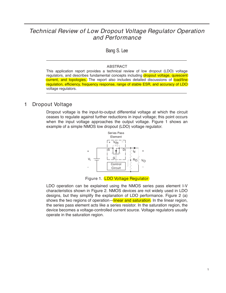
1 Dropout Voltage
Dropout voltage is the input-to-output differential voltage at which the circuit
ceases to regulate against further reductions in input voltage; this point occurs
when the input voltage approaches the output voltage. Figure 1 shows an
example of a simple NMOS low dropout (LDO) voltage regulator.
Series Pass
Element
_
Vds
+
+
Vi
_
S
D
G
Control
Circuit
Id
RO
+
VO
_
Figure 1. LDO Voltage Regulator
LDO operation can be explained using the NMOS series pass element I-V
characteristics shown in Figure 2. NMOS devices are not widely used in LDO
designs, but they simplify the explanation of LDO performance. Figure 2 (a)
shows the two regions of operation—linear and saturation. In the linear region,
the series pass element acts like a series resistor. In the saturation region, the
device becomes a voltage-controlled current source. Voltage regulators usually
operate in the saturation region.
1
�
Dropout Voltage
Linear Region
Saturation Region
Id
(Operation Like a Resistor)
(Operation Like a Current Source)
Slope = Ri
Vgs5
Vgs4
Vgs3
Vgs2
Vgs1
0
Vds(sat)
Vds = VI – VO
(a) I-V Characteristic of n-channel MOSFET
Series Pass Element
+
VI
_
S
D
Ri
Id
RO
+
VO
_
Series Pass Element
Rds
b V2
gs
S
G
+
_
Vgs
Id
D
RO
+
VO
_
+
VI
_
(b) LDO Equivalent Circuit in The Linear Region
(c) LDO Equivalent Circuit in The Saturation Region
Figure 2. Series Pass Element I-V Characteristic and LDO Equivalent Circuits
Figures 2 (b) and (c) show the LDO equivalent circuits for the two operating
regions. The control circuit is not shown. Figure 2 (c) shows the LDO equivalent
circuit in the saturation region (assume threshold voltage is zero). There is a
constant current source between the drain and source, which is a function of
gate-to-source voltage, Vgs. The drain current (load current) is given by
Id + bV2
gs
Where b is a current gain.
From equation (1), the series pass element acts like a constant current source
in the saturation region in terms of gate-to-source voltage. Under varying load
conditions, Vgs controls the LDO regulator to supply the demand output load.
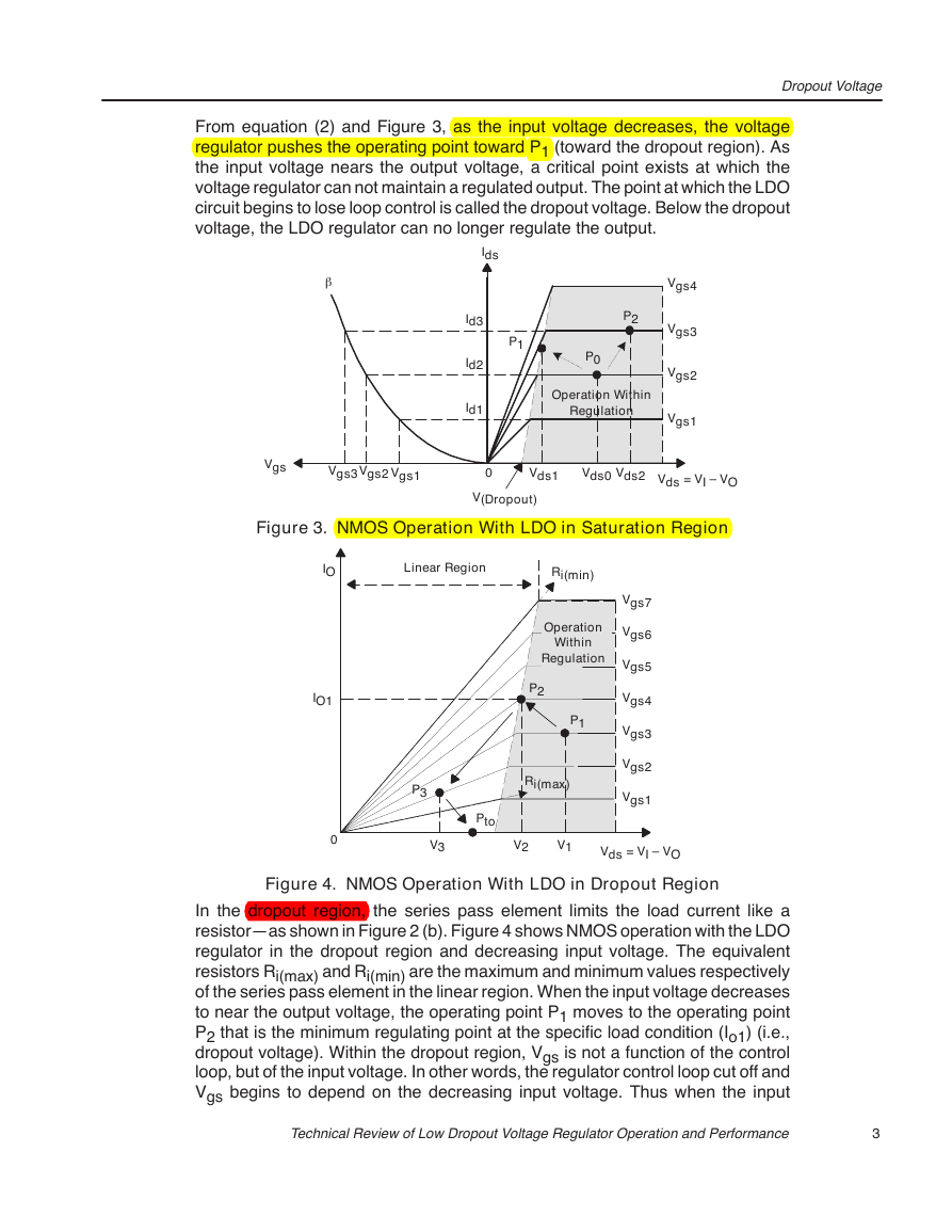
Figure 3 illustrates the LDO operation in the saturation region. When load current
increases from Id2 to Id3, the operating point moves from Po to P2, and the
input-to-output voltage differential, Vds, is given by
Vds + VI* VO
2
SLVA072
(1)
(2)
�
From equation (2) and Figure 3, as the input voltage decreases, the voltage
regulator pushes the operating point toward P1 (toward the dropout region). As
the input voltage nears the output voltage, a critical point exists at which the
voltage regulator can not maintain a regulated output. The point at which the LDO
circuit begins to lose loop control is called the dropout voltage. Below the dropout
voltage, the LDO regulator can no longer regulate the output.
Dropout Voltage
Ids
Id3
Id2
Id1
P2
P1
P0
Operation Within
Regulation
Vgs4
Vgs3
Vgs2
Vgs1
Vgs
Vgs3Vgs2
Vgs1
0
Vds1
Vds0
Vds2
Vds = VI – VO
V(Dropout)
Figure 3. NMOS Operation With LDO in Saturation Region
IO
Linear Region
Ri(min)
Operation
Within
Regulation
P2
P1
P3
Ri(max)
Pto
Vgs7
Vgs6
Vgs5
Vgs4
Vgs3
Vgs2
Vgs1
V3
V2
V1
Vds = VI – VO
IO1
0
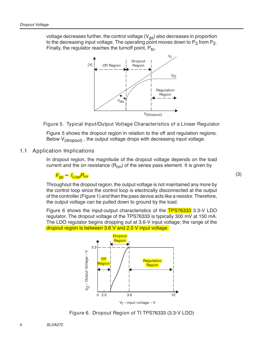
Figure 4. NMOS Operation With LDO in Dropout Region
In the dropout region, the series pass element limits the load current like a
resistor—as shown in Figure 2 (b). Figure 4 shows NMOS operation with the LDO
regulator in the dropout region and decreasing input voltage. The equivalent
resistors Ri(max) and Ri(min) are the maximum and minimum values respectively
of the series pass element in the linear region. When the input voltage decreases
to near the output voltage, the operating point P1 moves to the operating point
P2 that is the minimum regulating point at the specific load condition (Io1) (i.e.,
dropout voltage). Within the dropout region, Vgs is not a function of the control
loop, but of the input voltage. In other words, the regulator control loop cut off and
Vgs begins to depend on the decreasing input voltage. Thus when the input
Technical Review of Low Dropout Voltage Regulator Operation and Performance
3
b
�
Dropout Voltage
voltage decreases further, the control voltage (Vgs) also decreases in proportion
to the decreasing input voltage. The operating point moves down to P3 from P2.
Finally, the regulator reaches the turnoff point, Pto.
[V]
Off Region
Dropout
Region
VI
VO
Regulation
Region
Vds
V(dropout)
Figure 5. Typical Input/Output Voltage Characteristics of a Linear Regulator
Figure 5 shows the dropout region in relation to the off and regulation regions.
Below V(dropout) , the output voltage drops with decreasing input voltage.
1.1 Application Implications
In dropout region, the magnitude of the dropout voltage depends on the load
current and the on resistance (Ron) of the series pass element. It is given by
Vdo + ILoadRon
(3)
Throughout the dropout region, the output voltage is not maintained any more by
the control loop since the control loop is electrically disconnected at the output
of the controller (Figure 1) and then the pass device acts like a resistor. Therefore,
the output voltage can be pulled down to ground by the load.
Figure 6 shows the input-output characteristics of the TPS76333 3.3-V LDO
regulator. The dropout voltage of the TPS76333 is typically 300 mV at 150 mA.
The LDO regulator begins dropping out at 3.6-V input voltage; the range of the
dropout region is between 3.6 V and 2.0 V input voltage.
Dropout
Region
3.3
Off
Region
Regulation
Region
V
–
e
g
a
t
l
o
V
t
u
p
t
u
O
–
O
V
0
2.0
3.6
10
VI – input voltage – V
Figure 6. Dropout Region of TI TPS76333 (3.3-V LDO)
4
SLVA072
�




 2023年江西萍乡中考道德与法治真题及答案.doc
 2012年重庆南川中考生物真题及答案.doc
 2013年江西师范大学地理学综合及文艺理论基础考研真题.doc
 2020年四川甘孜小升初语文真题及答案I卷.doc
 2020年注册岩土工程师专业基础考试真题及答案.doc
 2023-2024学年福建省厦门市九年级上学期数学月考试题及答案.doc
 2021-2022学年辽宁省沈阳市大东区九年级上学期语文期末试题及答案.doc
 2022-2023学年北京东城区初三第一学期物理期末试卷及答案.doc
 2018上半年江西教师资格初中地理学科知识与教学能力真题及答案.doc
 2012年河北国家公务员申论考试真题及答案-省级.doc
 2020-2021学年江苏省扬州市江都区邵樊片九年级上学期数学第一次质量检测试题及答案.doc
 2022下半年黑龙江教师资格证中学综合素质真题及答案.doc