�
Reflective Optical Sensor with Transistor Output
TCRT5000(L)
Vishay Telefunken
Description
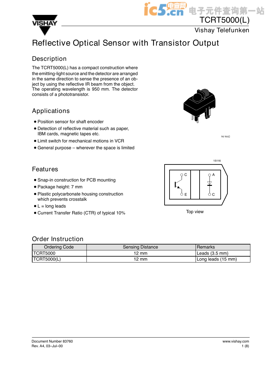
The TCRT5000(L) has a compact construction where
the emitting-light source and the detector are arranged
in the same direction to sense the presence of an ob-
ject by using the reflective IR beam from the object.
The operating wavelength is 950 mm. The detector
consists of a phototransistor.
Applications
D Position sensor for shaft encoder
D Detection of reflective material such as paper,
IBM cards, magnetic tapes etc.
D Limit switch for mechanical motions in VCR
D General purpose – wherever the space is limited
Features
D Snap-in construction for PCB mounting
D Package height: 7 mm
D Plastic polycarbonate housing construction
which prevents crosstalk
D L = long leads
D Current Transfer Ratio (CTR) of typical 10%
94 9442
15116
A
C
C
E
Top view
Order Instruction
Ordering Code
TCRT5000
TCRT5000(L)
Sensing Distance
12 mm
12 mm
Remarks
Leads (3.5 mm)
Long leads (15 mm)
Document Number 83760
Rev. A4, 03–Jul–00
www.vishay.com
1 (8)
�
TCRT5000(L)
Vishay Telefunken
Absolute Maximum Ratings
Input (Emitter)
Test Conditions
Symbol
Value
VR
IF
IFSM
PV
Tj
Symbol
VCEO
VECO
IC
PV
Tj
Symbol
Ptot
Tamb
Tstg
Tsd
5
60
3
100
100
Value
70
5
100
100
100
Value
200
–25 to +85
–25 to +100
260
Unit
V
mA
A
mW
°C
Unit
V
V
mA
mW
°C
Unit
mW
°C
°C
°C
Parameter
Reverse voltage
Forward current
Forward surge current
Power dissipation
Junction temperature
Output (Detector)
Parameter
Collector emitter voltage
Emitter collector voltage
Collector current
Power dissipation
Junction temperature
tp ≤ 10 mA
Tamb ≤ 25°C
Test Conditions
Tamb ≤ 55°C
Sensor
Parameter
Total power dissipation
Operation temperature range
Storage temperature range
Soldering temperature
Test Conditions
Tamb ≤ 25°C
2 mm from case, t ≤ 10 s
www.vishay.com
2 (8)
Document Number 83760
Rev. A4, 03–Jul–00
�
�
TCRT5000(L)
Vishay Telefunken
Electrical Characteristics (Tamb = 25°C)
Input (Emitter)
Parameter
Forward voltage
Junction capacitance
Test Conditions
Symbol
Min.
IF = 60 mA
VR = 0 V, f = 1 MHz
VF
Cj
Typ.
1.25
50
Max.
1.5
Output (Detector)
Parameter
Collector emitter voltage
Emitter collector voltage
Collector dark current
Sensor
Parameter
Collector current
Test Conditions
VCE = 5 V, IF = 10 mA,
D = 12 mm
IF = 10 mA, IC = 0.1 mA,
D = 12 mm
Collector emitter
saturation voltage
1) See test circuit
2) Test surface: Mirror (Mfr. Spindler a. Hoyer, Part No 340005)
VCEsat 1,2)
Test Conditions
IC = 1 mA
IE = 100 mA
VCE = 20 V, IF = 0, E = 0
Symbol
VCEO
VECO
ICEO
Min.
70
7
Typ.
Max.
10
200
Symbol
IC 1,2)
Min.
0.5
Typ.
1
Max.
2.1
0.4
Unit
V
pF
Unit
V
V
nA
Unit
mA
V
94 9226
IF
IC
VCC
A
96 12314
ÍÍÍÍÍÍÍÍÍ
ÍÍÍÍÍÍÍÍÍ
ÍÍÍÍÍÍÍÍÍ
Flat Mirror
∅ = 22.5 mm
Rem. 2
d = working distance
D = Distance
12 ± 0.2
7.0 ± 0.2
= package height
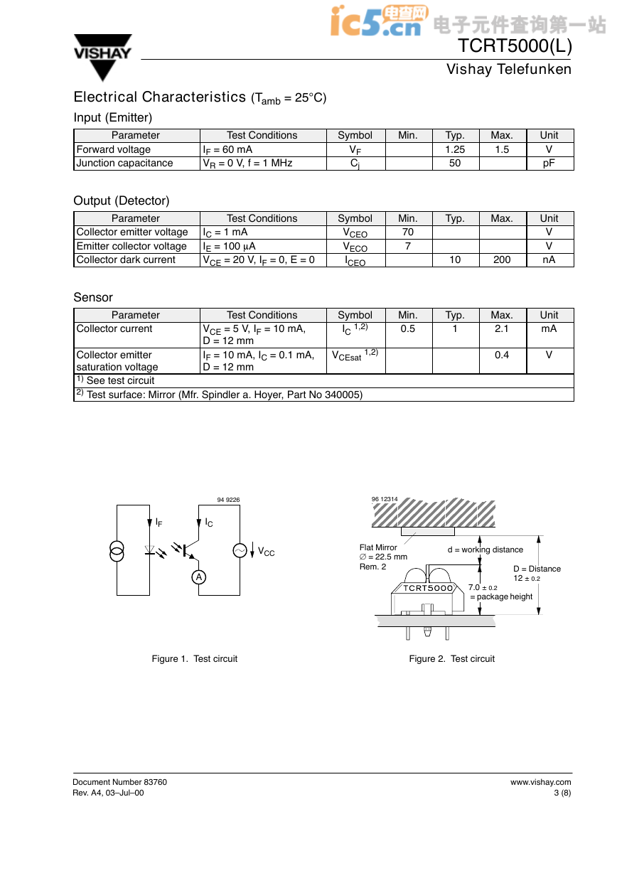
Figure 1. Test circuit
Figure 2. Test circuit
Document Number 83760
Rev. A4, 03–Jul–00
www.vishay.com
3 (8)
�
�
TCRT5000(L)
Vishay Telefunken
Typical Characteristics (Tamb = 25_C, unless otherwise specified)
300
200
100
Coupled device
Phototransistor
IR-diode
)
W
m
(
n
o
i
t
a
p
i
s
s
i
D
r
e
w
o
P
l
a
t
o
T
–
t
o
t
P
0
0
95 11071
25
50
75
100
Tamb – Ambient Temperature ( °C )
VCE=5V
10.000
1.000
0.100
0.010
)
A
m
(
t
n
e
r
r
u
C
r
o
t
c
e
l
l
o
C
–
I
C
0.001
0.1
1.0
10.0
100.0
96 11763
IF – Forward Current ( mA )
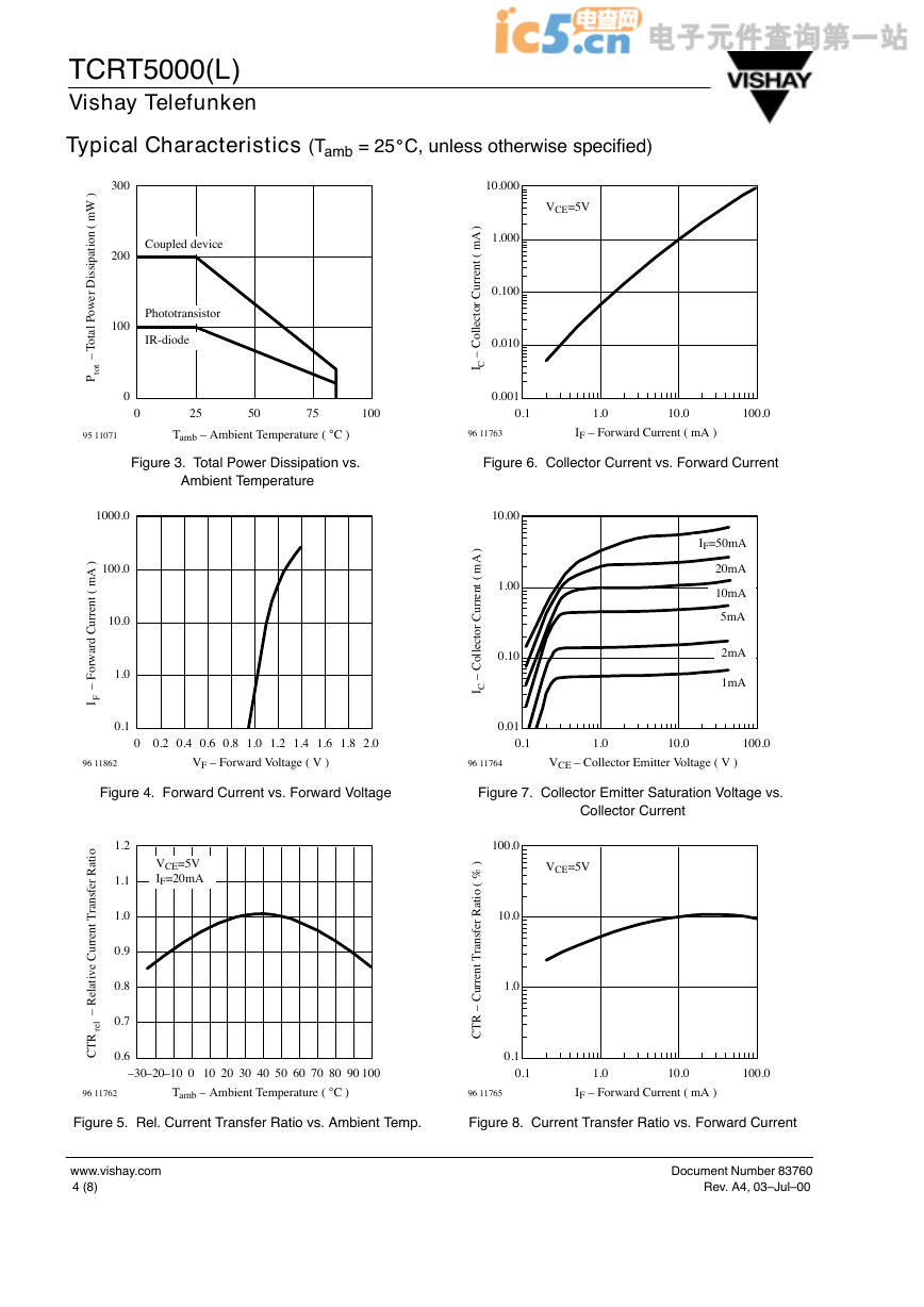
Figure 3. Total Power Dissipation vs.
Figure 6. Collector Current vs. Forward Current
Ambient Temperature
1000.0
100.0
)
A
m
(
t
n
e
r
r
u
C
d
r
a
w
r
o
F
–
I
F
10.0
1.0
0.1
0
0.2 0.4 0.6 0.8 1.0 1.2 1.4 1.6 1.8 2.0
10.00
1.00
0.10
)
A
m
(
t
n
e
r
r
u
C
r
o
t
c
e
l
l
o
C
–
I
C
0.01
0.1
IF=50mA
20mA
10mA
5mA
2mA
1mA
1.0
10.0
100.0
96 11862
VF – Forward Voltage ( V )
96 11764
VCE – Collector Emitter Voltage ( V )
Figure 4. Forward Current vs. Forward Voltage
Figure 7. Collector Emitter Saturation Voltage vs.
o
i
t
a
R
r
e
f
s
n
a
r
T
t
n
e
r
r
u
C
e
v
i
t
a
l
e
R
–
l
e
r
R
T
C
VCE=5V
IF=20mA
1.2
1.1
1.0
0.9
0.8
0.7
0.6
–30–20–10 0 10 20 30 40 50 60 70 80 90 100
96 11762
Tamb – Ambient Temperature ( °C )
%
(
o
i
t
a
R
r
e
f
s
n
a
r
T
t
n
e
r
r
u
C
–
R
T
C
Collector Current
VCE=5V
100.0
)
10.0
1.0
0.1
0.1
1.0
10.0
100.0
96 11765
IF – Forward Current ( mA )
Figure 5. Rel. Current Transfer Ratio vs. Ambient Temp.
Figure 8. Current Transfer Ratio vs. Forward Current
www.vishay.com
4 (8)
Document Number 83760
Rev. A4, 03–Jul–00
�


 2023年江西萍乡中考道德与法治真题及答案.doc
 2012年重庆南川中考生物真题及答案.doc
 2013年江西师范大学地理学综合及文艺理论基础考研真题.doc
 2020年四川甘孜小升初语文真题及答案I卷.doc
 2020年注册岩土工程师专业基础考试真题及答案.doc
 2023-2024学年福建省厦门市九年级上学期数学月考试题及答案.doc
 2021-2022学年辽宁省沈阳市大东区九年级上学期语文期末试题及答案.doc
 2022-2023学年北京东城区初三第一学期物理期末试卷及答案.doc
 2018上半年江西教师资格初中地理学科知识与教学能力真题及答案.doc
 2012年河北国家公务员申论考试真题及答案-省级.doc
 2020-2021学年江苏省扬州市江都区邵樊片九年级上学期数学第一次质量检测试题及答案.doc
 2022下半年黑龙江教师资格证中学综合素质真题及答案.doc