logo资料库

Infineon-TLF35584-DS-v02_00-EN.pdf

第1页 / 共244页
第2页 / 共244页
第3页 / 共244页
第4页 / 共244页
第5页 / 共244页
第6页 / 共244页
第7页 / 共244页
第8页 / 共244页
资料共244页,剩余部分请下载后查看
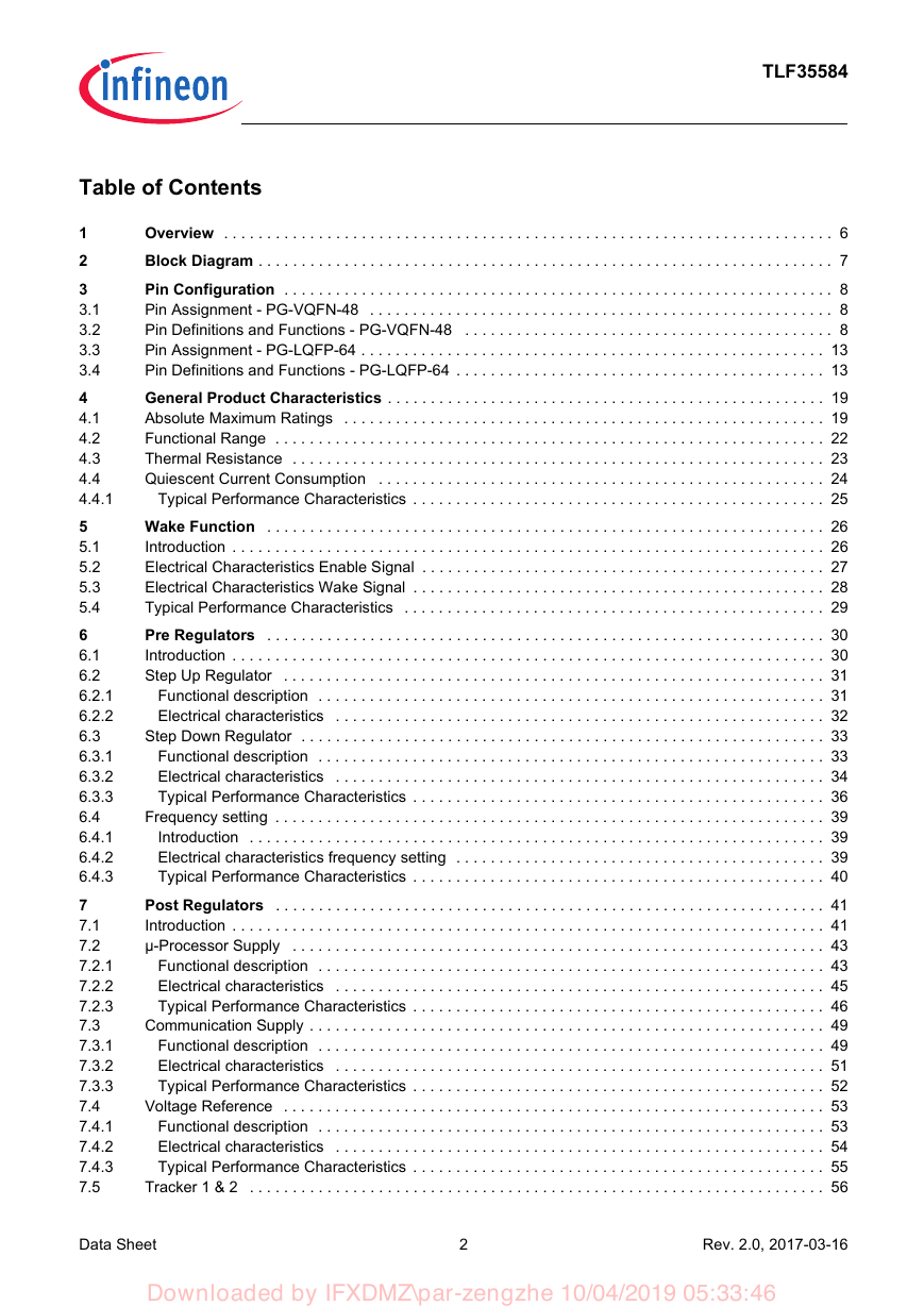
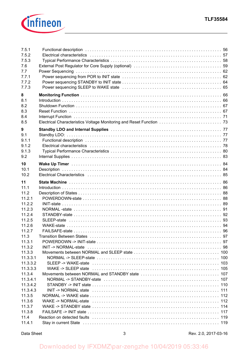
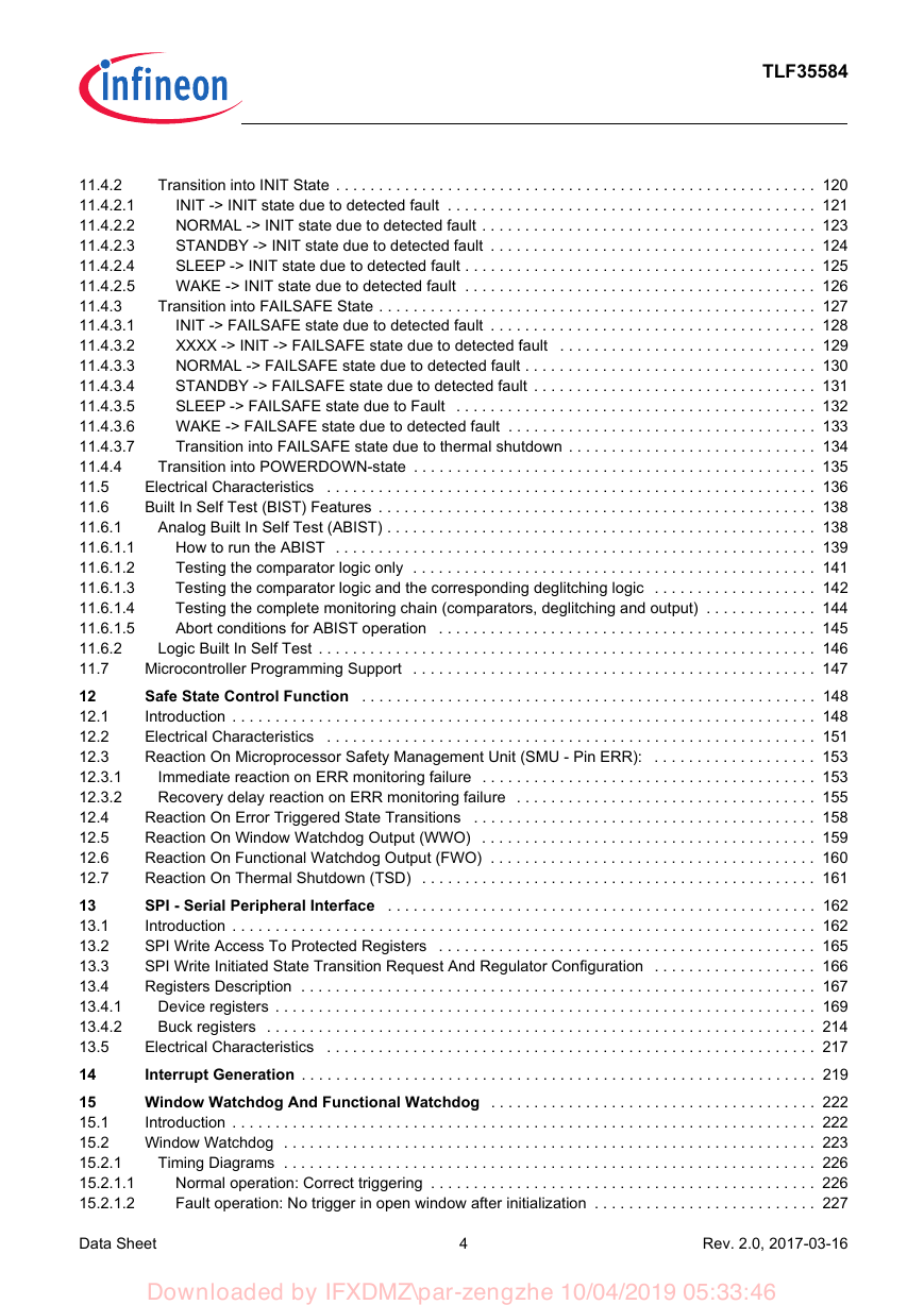
Table of Contents
1 Overview
2 Block Diagram
3 Pin Configuration
3.1 Pin Assignment - PG-VQFN-48
3.2 Pin Definitions and Functions - PG-VQFN-48
3.3 Pin Assignment - PG-LQFP-64
3.4 Pin Definitions and Functions - PG-LQFP-64
4 General Product Characteristics
4.1 Absolute Maximum Ratings
4.2 Functional Range
4.3 Thermal Resistance
4.4 Quiescent Current Consumption
4.4.1 Typical Performance Characteristics
5 Wake Function
5.1 Introduction
5.2 Electrical Characteristics Enable Signal
5.3 Electrical Characteristics Wake Signal
5.4 Typical Performance Characteristics
6 Pre Regulators
6.1 Introduction
6.2 Step Up Regulator
6.2.1 Functional description
6.2.2 Electrical characteristics
6.3 Step Down Regulator
6.3.1 Functional description
6.3.2 Electrical characteristics
6.3.3 Typical Performance Characteristics
6.4 Frequency setting
6.4.1 Introduction
6.4.2 Electrical characteristics frequency setting
6.4.3 Typical Performance Characteristics
7 Post Regulators
7.1 Introduction
7.2 µ-Processor Supply
7.2.1 Functional description
7.2.2 Electrical characteristics
7.2.3 Typical Performance Characteristics
7.3 Communication Supply
7.3.1 Functional description
7.3.2 Electrical characteristics
7.3.3 Typical Performance Characteristics
7.4 Voltage Reference
7.4.1 Functional description
7.4.2 Electrical characteristics
7.4.3 Typical Performance Characteristics
7.5 Tracker 1 & 2
7.5.1 Functional description
7.5.2 Electrical characteristics
7.5.3 Typical Performance Characteristics
7.6 External Post Regulator for Core Supply (optional)
7.7 Power Sequencing
7.7.1 Power sequencing from POR to INIT state
7.7.2 Power sequencing STANDBY to INIT state
7.7.3 Power sequencing SLEEP to WAKE state
8 Monitoring Function
8.1 Introduction
8.2 Shutdown Function
8.3 Reset Function
8.4 Interrupt Function
8.5 Electrical Characteristics Voltage Monitoring and Reset Function
9 Standby LDO and Internal Supplies
9.1 Standby LDO:
9.1.1 Functional description
9.1.2 Electrical characteristics
9.1.3 Typical Performance Characteristics
9.2 Internal Supplies
10 Wake Up Timer
10.1 Description
10.2 Electrical Characteristics
11 State Machine
11.1 Introduction
11.2 Description of States
11.2.1 POWERDOWN-state
11.2.2 INIT-state
11.2.3 NORMAL -state
11.2.4 STANDBY-state
11.2.5 SLEEP-state
11.2.6 WAKE-state
11.2.7 FAILSAFE-state
11.3 Transition Between States
11.3.1 POWERDOWN -> INIT-state
11.3.2 INIT -> NORMAL-state
11.3.3 Movements between NORMAL and SLEEP state
11.3.3.1 NORMAL -> SLEEP-state
11.3.3.2 SLEEP -> WAKE-state
11.3.3.3 WAKE -> SLEEP state
11.3.4 Movements between NORMAL and STANDBY state
11.3.4.1 NORMAL -> STANDBY-state
11.3.4.2 STANDBY -> INIT state
11.3.4.3 INIT -> NORMAL state
11.3.5 NORMAL -> WAKE state
11.3.6 WAKE -> NORMAL-state
11.3.7 WAKE -> STANDBY state
11.3.8 FAILSAFE -> INIT state
11.4 Reaction on detected faults
11.4.1 Stay in current State
11.4.2 Transition into INIT State
11.4.2.1 INIT -> INIT state due to detected fault
11.4.2.2 NORMAL -> INIT state due to detected fault
11.4.2.3 STANDBY -> INIT state due to detected fault
11.4.2.4 SLEEP -> INIT state due to detected fault
11.4.2.5 WAKE -> INIT state due to detected fault
11.4.3 Transition into FAILSAFE State
11.4.3.1 INIT -> FAILSAFE state due to detected fault
11.4.3.2 XXXX -> INIT -> FAILSAFE state due to detected fault
11.4.3.3 NORMAL -> FAILSAFE state due to detected fault
11.4.3.4 STANDBY -> FAILSAFE state due to detected fault
11.4.3.5 SLEEP -> FAILSAFE state due to Fault
11.4.3.6 WAKE -> FAILSAFE state due to detected fault
11.4.3.7 Transition into FAILSAFE state due to thermal shutdown
11.4.4 Transition into POWERDOWN-state
11.5 Electrical Characteristics
11.6 Built In Self Test (BIST) Features
11.6.1 Analog Built In Self Test (ABIST)
11.6.1.1 How to run the ABIST
11.6.1.2 Testing the comparator logic only
11.6.1.3 Testing the comparator logic and the corresponding deglitching logic
11.6.1.4 Testing the complete monitoring chain (comparators, deglitching and output)
11.6.1.5 Abort conditions for ABIST operation
11.6.2 Logic Built In Self Test
11.7 Microcontroller Programming Support
12 Safe State Control Function
12.1 Introduction
12.2 Electrical Characteristics
12.3 Reaction On Microprocessor Safety Management Unit (SMU - Pin ERR):
12.3.1 Immediate reaction on ERR monitoring failure
12.3.2 Recovery delay reaction on ERR monitoring failure
12.4 Reaction On Error Triggered State Transitions
12.5 Reaction On Window Watchdog Output (WWO)
12.6 Reaction On Functional Watchdog Output (FWO)
12.7 Reaction On Thermal Shutdown (TSD)
13 SPI - Serial Peripheral Interface
13.1 Introduction
13.2 SPI Write Access To Protected Registers
13.3 SPI Write Initiated State Transition Request And Regulator Configuration
13.4 Registers Description
13.4.1 Device registers
13.4.2 Buck registers
13.5 Electrical Characteristics
14 Interrupt Generation
15 Window Watchdog And Functional Watchdog
15.1 Introduction
15.2 Window Watchdog
15.2.1 Timing Diagrams
15.2.1.1 Normal operation: Correct triggering
15.2.1.2 Fault operation: No trigger in open window after initialization
15.2.1.3 Fault operation: No trigger in Open Window in steady state
15.2.1.4 Fault operation: False trigger in Closed Window after initialization
15.2.1.5 Fault operation: False trigger in Closed Window in steady state
15.2.2 Electrical characteristics
15.3 Functional Watchdog
15.3.1 Timing Diagrams
15.3.1.1 Normal operation: Correct triggering
15.3.1.2 Fault operation: Synchronization is missing
15.3.1.3 Fault operation: Answer is wrong
15.3.1.4 Fault operation: Missing response
16 Application Information
17 Package Outlines
18 Revision History
TLF35584 Multi Voltage Safety Micro Processor Supply TLF35584QVVS1 TLF35584QVVS2 TLF35584QKVS1 TLF35584QKVS2 Data Sheet Rev. 2.0, 2017-03-16 Automotive Power Downloaded by IFXDMZ\par-zengzhe 10/04/2019 05:33:46
TLF35584 Table of Contents 1 2 3 3.1 3.2 3.3 3.4 4 4.1 4.2 4.3 4.4 4.4.1 5 5.1 5.2 5.3 5.4 6 6.1 6.2 6.2.1 6.2.2 6.3 6.3.1 6.3.2 6.3.3 6.4 6.4.1 6.4.2 6.4.3 7 7.1 7.2 7.2.1 7.2.2 7.2.3 7.3 7.3.1 7.3.2 7.3.3 7.4 7.4.1 7.4.2 7.4.3 7.5 Overview . . . . . . . . . . . . . . . . . . . . . . . . . . . . . . . . . . . . . . . . . . . . . . . . . . . . . . . . . . . . . . . . . . . . . . . 6 Block Diagram . . . . . . . . . . . . . . . . . . . . . . . . . . . . . . . . . . . . . . . . . . . . . . . . . . . . . . . . . . . . . . . . . . . 7 Pin Configuration . . . . . . . . . . . . . . . . . . . . . . . . . . . . . . . . . . . . . . . . . . . . . . . . . . . . . . . . . . . . . . . . 8 Pin Assignment - PG-VQFN-48 . . . . . . . . . . . . . . . . . . . . . . . . . . . . . . . . . . . . . . . . . . . . . . . . . . . . . . 8 Pin Definitions and Functions - PG-VQFN-48 . . . . . . . . . . . . . . . . . . . . . . . . . . . . . . . . . . . . . . . . . . . 8 Pin Assignment - PG-LQFP-64 . . . . . . . . . . . . . . . . . . . . . . . . . . . . . . . . . . . . . . . . . . . . . . . . . . . . . . 13 Pin Definitions and Functions - PG-LQFP-64 . . . . . . . . . . . . . . . . . . . . . . . . . . . . . . . . . . . . . . . . . . . 13 General Product Characteristics . . . . . . . . . . . . . . . . . . . . . . . . . . . . . . . . . . . . . . . . . . . . . . . . . . . 19 Absolute Maximum Ratings . . . . . . . . . . . . . . . . . . . . . . . . . . . . . . . . . . . . . . . . . . . . . . . . . . . . . . . . 19 Functional Range . . . . . . . . . . . . . . . . . . . . . . . . . . . . . . . . . . . . . . . . . . . . . . . . . . . . . . . . . . . . . . . . 22 Thermal Resistance . . . . . . . . . . . . . . . . . . . . . . . . . . . . . . . . . . . . . . . . . . . . . . . . . . . . . . . . . . . . . . 23 Quiescent Current Consumption . . . . . . . . . . . . . . . . . . . . . . . . . . . . . . . . . . . . . . . . . . . . . . . . . . . . 24 Typical Performance Characteristics . . . . . . . . . . . . . . . . . . . . . . . . . . . . . . . . . . . . . . . . . . . . . . . . 25 Wake Function . . . . . . . . . . . . . . . . . . . . . . . . . . . . . . . . . . . . . . . . . . . . . . . . . . . . . . . . . . . . . . . . . 26 Introduction . . . . . . . . . . . . . . . . . . . . . . . . . . . . . . . . . . . . . . . . . . . . . . . . . . . . . . . . . . . . . . . . . . . . . 26 Electrical Characteristics Enable Signal . . . . . . . . . . . . . . . . . . . . . . . . . . . . . . . . . . . . . . . . . . . . . . . 27 Electrical Characteristics Wake Signal . . . . . . . . . . . . . . . . . . . . . . . . . . . . . . . . . . . . . . . . . . . . . . . . 28 Typical Performance Characteristics . . . . . . . . . . . . . . . . . . . . . . . . . . . . . . . . . . . . . . . . . . . . . . . . . 29 Pre Regulators . . . . . . . . . . . . . . . . . . . . . . . . . . . . . . . . . . . . . . . . . . . . . . . . . . . . . . . . . . . . . . . . . 30 Introduction . . . . . . . . . . . . . . . . . . . . . . . . . . . . . . . . . . . . . . . . . . . . . . . . . . . . . . . . . . . . . . . . . . . . . 30 Step Up Regulator . . . . . . . . . . . . . . . . . . . . . . . . . . . . . . . . . . . . . . . . . . . . . . . . . . . . . . . . . . . . . . . 31 Functional description . . . . . . . . . . . . . . . . . . . . . . . . . . . . . . . . . . . . . . . . . . . . . . . . . . . . . . . . . . . 31 Electrical characteristics . . . . . . . . . . . . . . . . . . . . . . . . . . . . . . . . . . . . . . . . . . . . . . . . . . . . . . . . . 32 Step Down Regulator . . . . . . . . . . . . . . . . . . . . . . . . . . . . . . . . . . . . . . . . . . . . . . . . . . . . . . . . . . . . . 33 Functional description . . . . . . . . . . . . . . . . . . . . . . . . . . . . . . . . . . . . . . . . . . . . . . . . . . . . . . . . . . . 33 Electrical characteristics . . . . . . . . . . . . . . . . . . . . . . . . . . . . . . . . . . . . . . . . . . . . . . . . . . . . . . . . . 34 Typical Performance Characteristics . . . . . . . . . . . . . . . . . . . . . . . . . . . . . . . . . . . . . . . . . . . . . . . . 36 Frequency setting . . . . . . . . . . . . . . . . . . . . . . . . . . . . . . . . . . . . . . . . . . . . . . . . . . . . . . . . . . . . . . . . 39 Introduction . . . . . . . . . . . . . . . . . . . . . . . . . . . . . . . . . . . . . . . . . . . . . . . . . . . . . . . . . . . . . . . . . . . 39 Electrical characteristics frequency setting . . . . . . . . . . . . . . . . . . . . . . . . . . . . . . . . . . . . . . . . . . . 39 Typical Performance Characteristics . . . . . . . . . . . . . . . . . . . . . . . . . . . . . . . . . . . . . . . . . . . . . . . . 40 Post Regulators . . . . . . . . . . . . . . . . . . . . . . . . . . . . . . . . . . . . . . . . . . . . . . . . . . . . . . . . . . . . . . . . 41 Introduction . . . . . . . . . . . . . . . . . . . . . . . . . . . . . . . . . . . . . . . . . . . . . . . . . . . . . . . . . . . . . . . . . . . . . 41 µ-Processor Supply . . . . . . . . . . . . . . . . . . . . . . . . . . . . . . . . . . . . . . . . . . . . . . . . . . . . . . . . . . . . . . 43 Functional description . . . . . . . . . . . . . . . . . . . . . . . . . . . . . . . . . . . . . . . . . . . . . . . . . . . . . . . . . . . 43 Electrical characteristics . . . . . . . . . . . . . . . . . . . . . . . . . . . . . . . . . . . . . . . . . . . . . . . . . . . . . . . . . 45 Typical Performance Characteristics . . . . . . . . . . . . . . . . . . . . . . . . . . . . . . . . . . . . . . . . . . . . . . . . 46 Communication Supply . . . . . . . . . . . . . . . . . . . . . . . . . . . . . . . . . . . . . . . . . . . . . . . . . . . . . . . . . . . . 49 Functional description . . . . . . . . . . . . . . . . . . . . . . . . . . . . . . . . . . . . . . . . . . . . . . . . . . . . . . . . . . . 49 Electrical characteristics . . . . . . . . . . . . . . . . . . . . . . . . . . . . . . . . . . . . . . . . . . . . . . . . . . . . . . . . . 51 Typical Performance Characteristics . . . . . . . . . . . . . . . . . . . . . . . . . . . . . . . . . . . . . . . . . . . . . . . . 52 Voltage Reference . . . . . . . . . . . . . . . . . . . . . . . . . . . . . . . . . . . . . . . . . . . . . . . . . . . . . . . . . . . . . . . 53 Functional description . . . . . . . . . . . . . . . . . . . . . . . . . . . . . . . . . . . . . . . . . . . . . . . . . . . . . . . . . . . 53 Electrical characteristics . . . . . . . . . . . . . . . . . . . . . . . . . . . . . . . . . . . . . . . . . . . . . . . . . . . . . . . . . 54 Typical Performance Characteristics . . . . . . . . . . . . . . . . . . . . . . . . . . . . . . . . . . . . . . . . . . . . . . . . 55 Tracker 1 & 2 . . . . . . . . . . . . . . . . . . . . . . . . . . . . . . . . . . . . . . . . . . . . . . . . . . . . . . . . . . . . . . . . . . . 56 Data Sheet 2 Rev. 2.0, 2017-03-16 Downloaded by IFXDMZ\par-zengzhe 10/04/2019 05:33:46
TLF35584 7.5.1 7.5.2 7.5.3 7.6 7.7 7.7.1 7.7.2 7.7.3 8 8.1 8.2 8.3 8.4 8.5 9 9.1 9.1.1 9.1.2 9.1.3 9.2 10 10.1 10.2 11 11.1 11.2 11.2.1 11.2.2 11.2.3 11.2.4 11.2.5 11.2.6 11.2.7 11.3 11.3.1 11.3.2 11.3.3 11.3.3.1 11.3.3.2 11.3.3.3 11.3.4 11.3.4.1 11.3.4.2 11.3.4.3 11.3.5 11.3.6 11.3.7 11.3.8 11.4 11.4.1 Functional description . . . . . . . . . . . . . . . . . . . . . . . . . . . . . . . . . . . . . . . . . . . . . . . . . . . . . . . . . . . 56 Electrical characteristics . . . . . . . . . . . . . . . . . . . . . . . . . . . . . . . . . . . . . . . . . . . . . . . . . . . . . . . . . 57 Typical Performance Characteristics . . . . . . . . . . . . . . . . . . . . . . . . . . . . . . . . . . . . . . . . . . . . . . . . 58 External Post Regulator for Core Supply (optional) . . . . . . . . . . . . . . . . . . . . . . . . . . . . . . . . . . . . . . 59 Power Sequencing . . . . . . . . . . . . . . . . . . . . . . . . . . . . . . . . . . . . . . . . . . . . . . . . . . . . . . . . . . . . . . . 62 Power sequencing from POR to INIT state . . . . . . . . . . . . . . . . . . . . . . . . . . . . . . . . . . . . . . . . . . . 62 Power sequencing STANDBY to INIT state . . . . . . . . . . . . . . . . . . . . . . . . . . . . . . . . . . . . . . . . . . . 64 Power sequencing SLEEP to WAKE state . . . . . . . . . . . . . . . . . . . . . . . . . . . . . . . . . . . . . . . . . . . 65 Monitoring Function . . . . . . . . . . . . . . . . . . . . . . . . . . . . . . . . . . . . . . . . . . . . . . . . . . . . . . . . . . . . . 66 Introduction . . . . . . . . . . . . . . . . . . . . . . . . . . . . . . . . . . . . . . . . . . . . . . . . . . . . . . . . . . . . . . . . . . . . . 66 Shutdown Function . . . . . . . . . . . . . . . . . . . . . . . . . . . . . . . . . . . . . . . . . . . . . . . . . . . . . . . . . . . . . . . 67 Reset Function . . . . . . . . . . . . . . . . . . . . . . . . . . . . . . . . . . . . . . . . . . . . . . . . . . . . . . . . . . . . . . . . . . 67 Interrupt Function . . . . . . . . . . . . . . . . . . . . . . . . . . . . . . . . . . . . . . . . . . . . . . . . . . . . . . . . . . . . . . . . 71 Electrical Characteristics Voltage Monitoring and Reset Function . . . . . . . . . . . . . . . . . . . . . . . . . . . 73 Standby LDO and Internal Supplies . . . . . . . . . . . . . . . . . . . . . . . . . . . . . . . . . . . . . . . . . . . . . . . . 77 Standby LDO: . . . . . . . . . . . . . . . . . . . . . . . . . . . . . . . . . . . . . . . . . . . . . . . . . . . . . . . . . . . . . . . . . . . 77 Functional description . . . . . . . . . . . . . . . . . . . . . . . . . . . . . . . . . . . . . . . . . . . . . . . . . . . . . . . . . . . 77 Electrical characteristics . . . . . . . . . . . . . . . . . . . . . . . . . . . . . . . . . . . . . . . . . . . . . . . . . . . . . . . . . 78 Typical Performance Characteristics . . . . . . . . . . . . . . . . . . . . . . . . . . . . . . . . . . . . . . . . . . . . . . . . 80 Internal Supplies . . . . . . . . . . . . . . . . . . . . . . . . . . . . . . . . . . . . . . . . . . . . . . . . . . . . . . . . . . . . . . . . . 83 Wake Up Timer . . . . . . . . . . . . . . . . . . . . . . . . . . . . . . . . . . . . . . . . . . . . . . . . . . . . . . . . . . . . . . . . . 84 Description . . . . . . . . . . . . . . . . . . . . . . . . . . . . . . . . . . . . . . . . . . . . . . . . . . . . . . . . . . . . . . . . . . . . . 84 Electrical Characteristics . . . . . . . . . . . . . . . . . . . . . . . . . . . . . . . . . . . . . . . . . . . . . . . . . . . . . . . . . . 85 State Machine . . . . . . . . . . . . . . . . . . . . . . . . . . . . . . . . . . . . . . . . . . . . . . . . . . . . . . . . . . . . . . . . . . 86 Introduction . . . . . . . . . . . . . . . . . . . . . . . . . . . . . . . . . . . . . . . . . . . . . . . . . . . . . . . . . . . . . . . . . . . . . 86 Description of States . . . . . . . . . . . . . . . . . . . . . . . . . . . . . . . . . . . . . . . . . . . . . . . . . . . . . . . . . . . . . . 88 POWERDOWN-state . . . . . . . . . . . . . . . . . . . . . . . . . . . . . . . . . . . . . . . . . . . . . . . . . . . . . . . . . . . . 88 INIT-state . . . . . . . . . . . . . . . . . . . . . . . . . . . . . . . . . . . . . . . . . . . . . . . . . . . . . . . . . . . . . . . . . . . . . 89 NORMAL -state . . . . . . . . . . . . . . . . . . . . . . . . . . . . . . . . . . . . . . . . . . . . . . . . . . . . . . . . . . . . . . . . 91 STANDBY-state . . . . . . . . . . . . . . . . . . . . . . . . . . . . . . . . . . . . . . . . . . . . . . . . . . . . . . . . . . . . . . . . 92 SLEEP-state . . . . . . . . . . . . . . . . . . . . . . . . . . . . . . . . . . . . . . . . . . . . . . . . . . . . . . . . . . . . . . . . . . 93 WAKE-state . . . . . . . . . . . . . . . . . . . . . . . . . . . . . . . . . . . . . . . . . . . . . . . . . . . . . . . . . . . . . . . . . . . 94 FAILSAFE-state . . . . . . . . . . . . . . . . . . . . . . . . . . . . . . . . . . . . . . . . . . . . . . . . . . . . . . . . . . . . . . . . 96 Transition Between States . . . . . . . . . . . . . . . . . . . . . . . . . . . . . . . . . . . . . . . . . . . . . . . . . . . . . . . . . 97 POWERDOWN -> INIT-state . . . . . . . . . . . . . . . . . . . . . . . . . . . . . . . . . . . . . . . . . . . . . . . . . . . . . . 97 INIT -> NORMAL-state . . . . . . . . . . . . . . . . . . . . . . . . . . . . . . . . . . . . . . . . . . . . . . . . . . . . . . . . . . 98 Movements between NORMAL and SLEEP state . . . . . . . . . . . . . . . . . . . . . . . . . . . . . . . . . . . . . 100 NORMAL -> SLEEP-state . . . . . . . . . . . . . . . . . . . . . . . . . . . . . . . . . . . . . . . . . . . . . . . . . . . . . 100 SLEEP -> WAKE-state . . . . . . . . . . . . . . . . . . . . . . . . . . . . . . . . . . . . . . . . . . . . . . . . . . . . . . . 103 WAKE -> SLEEP state . . . . . . . . . . . . . . . . . . . . . . . . . . . . . . . . . . . . . . . . . . . . . . . . . . . . . . . 105 Movements between NORMAL and STANDBY state . . . . . . . . . . . . . . . . . . . . . . . . . . . . . . . . . . 107 NORMAL -> STANDBY-state . . . . . . . . . . . . . . . . . . . . . . . . . . . . . . . . . . . . . . . . . . . . . . . . . . 107 STANDBY -> INIT state . . . . . . . . . . . . . . . . . . . . . . . . . . . . . . . . . . . . . . . . . . . . . . . . . . . . . . . 110 INIT -> NORMAL state . . . . . . . . . . . . . . . . . . . . . . . . . . . . . . . . . . . . . . . . . . . . . . . . . . . . . . . 111 NORMAL -> WAKE state . . . . . . . . . . . . . . . . . . . . . . . . . . . . . . . . . . . . . . . . . . . . . . . . . . . . . . . . 112 WAKE -> NORMAL-state . . . . . . . . . . . . . . . . . . . . . . . . . . . . . . . . . . . . . . . . . . . . . . . . . . . . . . . 112 WAKE -> STANDBY state . . . . . . . . . . . . . . . . . . . . . . . . . . . . . . . . . . . . . . . . . . . . . . . . . . . . . . . 114 FAILSAFE -> INIT state . . . . . . . . . . . . . . . . . . . . . . . . . . . . . . . . . . . . . . . . . . . . . . . . . . . . . . . . . 117 Reaction on detected faults . . . . . . . . . . . . . . . . . . . . . . . . . . . . . . . . . . . . . . . . . . . . . . . . . . . . . . . 119 Stay in current State . . . . . . . . . . . . . . . . . . . . . . . . . . . . . . . . . . . . . . . . . . . . . . . . . . . . . . . . . . . 119 Data Sheet 3 Rev. 2.0, 2017-03-16 Downloaded by IFXDMZ\par-zengzhe 10/04/2019 05:33:46
TLF35584 11.4.2 11.4.2.1 11.4.2.2 11.4.2.3 11.4.2.4 11.4.2.5 11.4.3 11.4.3.1 11.4.3.2 11.4.3.3 11.4.3.4 11.4.3.5 11.4.3.6 11.4.3.7 11.4.4 11.5 11.6 11.6.1 11.6.1.1 11.6.1.2 11.6.1.3 11.6.1.4 11.6.1.5 11.6.2 11.7 12 12.1 12.2 12.3 12.3.1 12.3.2 12.4 12.5 12.6 12.7 13 13.1 13.2 13.3 13.4 13.4.1 13.4.2 13.5 14 15 15.1 15.2 15.2.1 15.2.1.1 15.2.1.2 Transition into INIT State . . . . . . . . . . . . . . . . . . . . . . . . . . . . . . . . . . . . . . . . . . . . . . . . . . . . . . . . 120 INIT -> INIT state due to detected fault . . . . . . . . . . . . . . . . . . . . . . . . . . . . . . . . . . . . . . . . . . . 121 NORMAL -> INIT state due to detected fault . . . . . . . . . . . . . . . . . . . . . . . . . . . . . . . . . . . . . . . 123 STANDBY -> INIT state due to detected fault . . . . . . . . . . . . . . . . . . . . . . . . . . . . . . . . . . . . . . 124 SLEEP -> INIT state due to detected fault . . . . . . . . . . . . . . . . . . . . . . . . . . . . . . . . . . . . . . . . . 125 WAKE -> INIT state due to detected fault . . . . . . . . . . . . . . . . . . . . . . . . . . . . . . . . . . . . . . . . . 126 Transition into FAILSAFE State . . . . . . . . . . . . . . . . . . . . . . . . . . . . . . . . . . . . . . . . . . . . . . . . . . . 127 INIT -> FAILSAFE state due to detected fault . . . . . . . . . . . . . . . . . . . . . . . . . . . . . . . . . . . . . . 128 XXXX -> INIT -> FAILSAFE state due to detected fault . . . . . . . . . . . . . . . . . . . . . . . . . . . . . . 129 NORMAL -> FAILSAFE state due to detected fault . . . . . . . . . . . . . . . . . . . . . . . . . . . . . . . . . . 130 STANDBY -> FAILSAFE state due to detected fault . . . . . . . . . . . . . . . . . . . . . . . . . . . . . . . . . 131 SLEEP -> FAILSAFE state due to Fault . . . . . . . . . . . . . . . . . . . . . . . . . . . . . . . . . . . . . . . . . . 132 WAKE -> FAILSAFE state due to detected fault . . . . . . . . . . . . . . . . . . . . . . . . . . . . . . . . . . . . 133 Transition into FAILSAFE state due to thermal shutdown . . . . . . . . . . . . . . . . . . . . . . . . . . . . . 134 Transition into POWERDOWN-state . . . . . . . . . . . . . . . . . . . . . . . . . . . . . . . . . . . . . . . . . . . . . . . 135 Electrical Characteristics . . . . . . . . . . . . . . . . . . . . . . . . . . . . . . . . . . . . . . . . . . . . . . . . . . . . . . . . . 136 Built In Self Test (BIST) Features . . . . . . . . . . . . . . . . . . . . . . . . . . . . . . . . . . . . . . . . . . . . . . . . . . . 138 Analog Built In Self Test (ABIST) . . . . . . . . . . . . . . . . . . . . . . . . . . . . . . . . . . . . . . . . . . . . . . . . . . 138 How to run the ABIST . . . . . . . . . . . . . . . . . . . . . . . . . . . . . . . . . . . . . . . . . . . . . . . . . . . . . . . . 139 Testing the comparator logic only . . . . . . . . . . . . . . . . . . . . . . . . . . . . . . . . . . . . . . . . . . . . . . . 141 Testing the comparator logic and the corresponding deglitching logic . . . . . . . . . . . . . . . . . . . 142 Testing the complete monitoring chain (comparators, deglitching and output) . . . . . . . . . . . . . 144 Abort conditions for ABIST operation . . . . . . . . . . . . . . . . . . . . . . . . . . . . . . . . . . . . . . . . . . . . 145 Logic Built In Self Test . . . . . . . . . . . . . . . . . . . . . . . . . . . . . . . . . . . . . . . . . . . . . . . . . . . . . . . . . . 146 Microcontroller Programming Support . . . . . . . . . . . . . . . . . . . . . . . . . . . . . . . . . . . . . . . . . . . . . . . 147 Safe State Control Function . . . . . . . . . . . . . . . . . . . . . . . . . . . . . . . . . . . . . . . . . . . . . . . . . . . . . 148 Introduction . . . . . . . . . . . . . . . . . . . . . . . . . . . . . . . . . . . . . . . . . . . . . . . . . . . . . . . . . . . . . . . . . . . . 148 Electrical Characteristics . . . . . . . . . . . . . . . . . . . . . . . . . . . . . . . . . . . . . . . . . . . . . . . . . . . . . . . . . 151 Reaction On Microprocessor Safety Management Unit (SMU - Pin ERR): . . . . . . . . . . . . . . . . . . . 153 Immediate reaction on ERR monitoring failure . . . . . . . . . . . . . . . . . . . . . . . . . . . . . . . . . . . . . . . 153 Recovery delay reaction on ERR monitoring failure . . . . . . . . . . . . . . . . . . . . . . . . . . . . . . . . . . . 155 Reaction On Error Triggered State Transitions . . . . . . . . . . . . . . . . . . . . . . . . . . . . . . . . . . . . . . . . 158 Reaction On Window Watchdog Output (WWO) . . . . . . . . . . . . . . . . . . . . . . . . . . . . . . . . . . . . . . . 159 Reaction On Functional Watchdog Output (FWO) . . . . . . . . . . . . . . . . . . . . . . . . . . . . . . . . . . . . . . 160 Reaction On Thermal Shutdown (TSD) . . . . . . . . . . . . . . . . . . . . . . . . . . . . . . . . . . . . . . . . . . . . . . 161 SPI - Serial Peripheral Interface . . . . . . . . . . . . . . . . . . . . . . . . . . . . . . . . . . . . . . . . . . . . . . . . . . 162 Introduction . . . . . . . . . . . . . . . . . . . . . . . . . . . . . . . . . . . . . . . . . . . . . . . . . . . . . . . . . . . . . . . . . . . . 162 SPI Write Access To Protected Registers . . . . . . . . . . . . . . . . . . . . . . . . . . . . . . . . . . . . . . . . . . . . 165 SPI Write Initiated State Transition Request And Regulator Configuration . . . . . . . . . . . . . . . . . . . 166 Registers Description . . . . . . . . . . . . . . . . . . . . . . . . . . . . . . . . . . . . . . . . . . . . . . . . . . . . . . . . . . . . 167 Device registers . . . . . . . . . . . . . . . . . . . . . . . . . . . . . . . . . . . . . . . . . . . . . . . . . . . . . . . . . . . . . . . 169 Buck registers . . . . . . . . . . . . . . . . . . . . . . . . . . . . . . . . . . . . . . . . . . . . . . . . . . . . . . . . . . . . . . . . 214 Electrical Characteristics . . . . . . . . . . . . . . . . . . . . . . . . . . . . . . . . . . . . . . . . . . . . . . . . . . . . . . . . . 217 Interrupt Generation . . . . . . . . . . . . . . . . . . . . . . . . . . . . . . . . . . . . . . . . . . . . . . . . . . . . . . . . . . . . 219 Window Watchdog And Functional Watchdog . . . . . . . . . . . . . . . . . . . . . . . . . . . . . . . . . . . . . . 222 Introduction . . . . . . . . . . . . . . . . . . . . . . . . . . . . . . . . . . . . . . . . . . . . . . . . . . . . . . . . . . . . . . . . . . . . 222 Window Watchdog . . . . . . . . . . . . . . . . . . . . . . . . . . . . . . . . . . . . . . . . . . . . . . . . . . . . . . . . . . . . . . 223 Timing Diagrams . . . . . . . . . . . . . . . . . . . . . . . . . . . . . . . . . . . . . . . . . . . . . . . . . . . . . . . . . . . . . . 226 Normal operation: Correct triggering . . . . . . . . . . . . . . . . . . . . . . . . . . . . . . . . . . . . . . . . . . . . . 226 Fault operation: No trigger in open window after initialization . . . . . . . . . . . . . . . . . . . . . . . . . . 227 Data Sheet 4 Rev. 2.0, 2017-03-16 Downloaded by IFXDMZ\par-zengzhe 10/04/2019 05:33:46
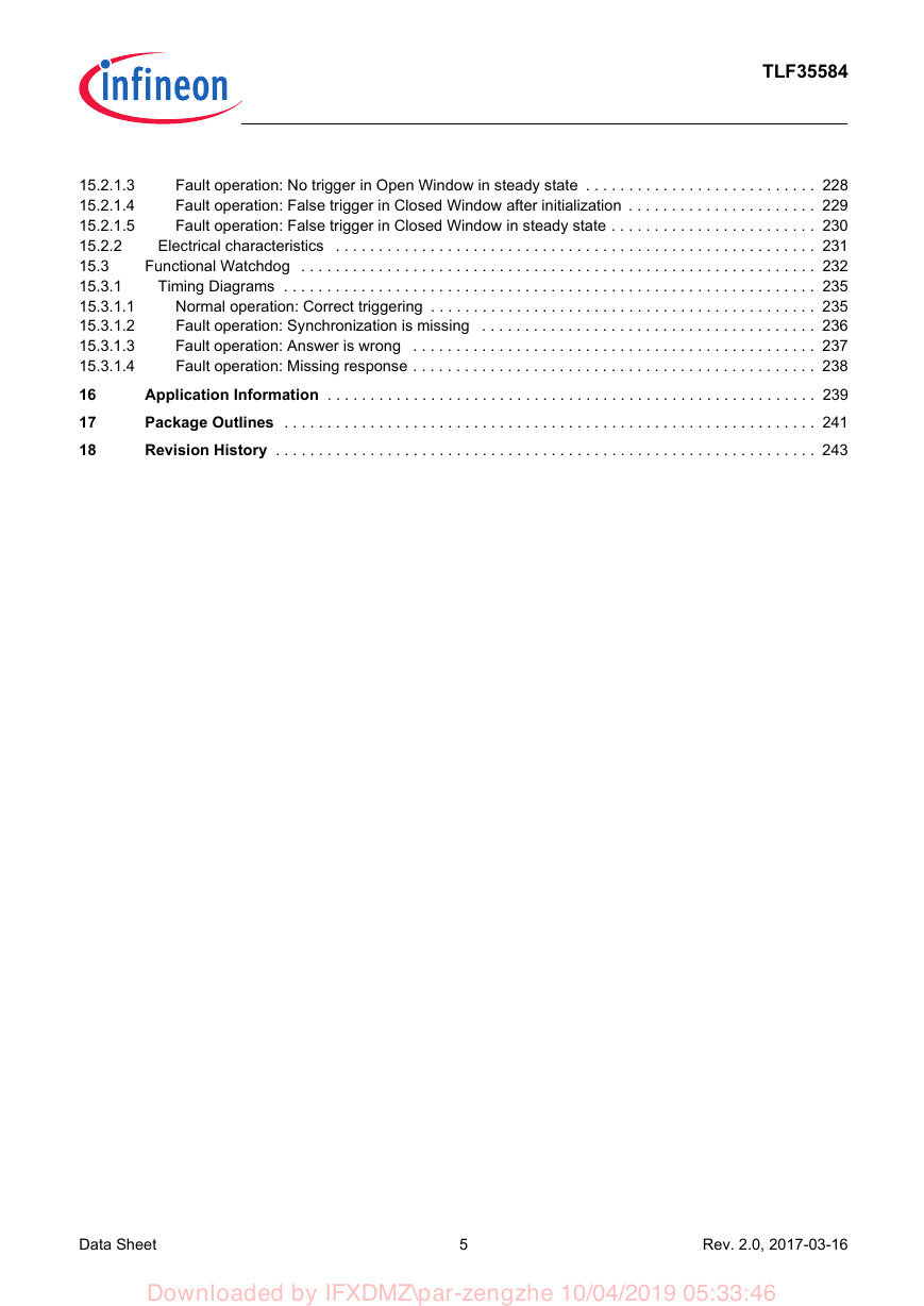
TLF35584 15.2.1.3 15.2.1.4 15.2.1.5 15.2.2 15.3 15.3.1 15.3.1.1 15.3.1.2 15.3.1.3 15.3.1.4 16 17 18 Fault operation: No trigger in Open Window in steady state . . . . . . . . . . . . . . . . . . . . . . . . . . . 228 Fault operation: False trigger in Closed Window after initialization . . . . . . . . . . . . . . . . . . . . . . 229 Fault operation: False trigger in Closed Window in steady state . . . . . . . . . . . . . . . . . . . . . . . . 230 Electrical characteristics . . . . . . . . . . . . . . . . . . . . . . . . . . . . . . . . . . . . . . . . . . . . . . . . . . . . . . . . 231 Functional Watchdog . . . . . . . . . . . . . . . . . . . . . . . . . . . . . . . . . . . . . . . . . . . . . . . . . . . . . . . . . . . . 232 Timing Diagrams . . . . . . . . . . . . . . . . . . . . . . . . . . . . . . . . . . . . . . . . . . . . . . . . . . . . . . . . . . . . . . 235 Normal operation: Correct triggering . . . . . . . . . . . . . . . . . . . . . . . . . . . . . . . . . . . . . . . . . . . . . 235 Fault operation: Synchronization is missing . . . . . . . . . . . . . . . . . . . . . . . . . . . . . . . . . . . . . . . 236 Fault operation: Answer is wrong . . . . . . . . . . . . . . . . . . . . . . . . . . . . . . . . . . . . . . . . . . . . . . . 237 Fault operation: Missing response . . . . . . . . . . . . . . . . . . . . . . . . . . . . . . . . . . . . . . . . . . . . . . . 238 Application Information . . . . . . . . . . . . . . . . . . . . . . . . . . . . . . . . . . . . . . . . . . . . . . . . . . . . . . . . . 239 Package Outlines . . . . . . . . . . . . . . . . . . . . . . . . . . . . . . . . . . . . . . . . . . . . . . . . . . . . . . . . . . . . . . 241 Revision History . . . . . . . . . . . . . . . . . . . . . . . . . . . . . . . . . . . . . . . . . . . . . . . . . . . . . . . . . . . . . . . 243 Data Sheet 5 Rev. 2.0, 2017-03-16 Downloaded by IFXDMZ\par-zengzhe 10/04/2019 05:33:46
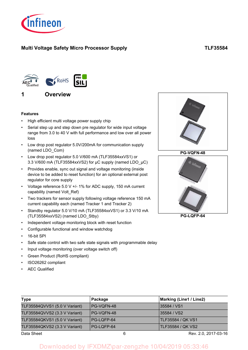
Multi Voltage Safety Micro Processor Supply TLF35584 1 Overview Features • High efficient multi voltage power supply chip • Serial step up and step down pre regulator for wide input voltage • range from 3.0 to 40 V with full performance and low over all power loss Low drop post regulator 5.0V/200mA for communication supply (named LDO_Com) Low drop post regulator 5.0 V/600 mA (TLF35584xxVS1) or 3.3 V/600 mA (TLF35584xxVS2) for µC supply (named LDO_µC) • Provides enable, sync out signal and voltage monitoring (inside • device to be added to reset function) for an optional external post regulator for core supply • Voltage reference 5.0 V +/- 1% for ADC supply, 150 mA current capability (named Volt_Ref) • Two trackers for sensor supply following voltage reference 150 mA current capability each (named Tracker 1 and Tracker 2) • Standby regulator 5.0 V/10 mA (TLF35584xxVS1) or 3.3 V/10 mA 16-bit SPI (TLF35584xxVS2) (named LDO_Stby) Independent voltage monitoring block with reset function • • Configurable functional and window watchdog • • Safe state control with two safe state signals with programmable delay • • Green Product (RoHS compliant) • • AEC Qualified Input voltage monitoring (over voltage switch off) ISO26262 compliant PG-VQFN-48 PG-LQFP-64 Type TLF35584QVVS1 (5.0 V Variant) TLF35584QVVS2 (3.3 V Variant) TLF35584QKVS1 (5.0 V Variant) TLF35584QKVS2 (3.3 V Variant) Data Sheet Package PG-VQFN-48 PG-VQFN-48 PG-LQFP-64 PG-LQFP-64 Marking (Line1 / Line2) 35584 / VS1 35584 / VS2 TLF35584 / QK VS1 TLF35584 / QK VS2 6 Rev. 2.0, 2017-03-16 Downloaded by IFXDMZ\par-zengzhe 10/04/2019 05:33:46
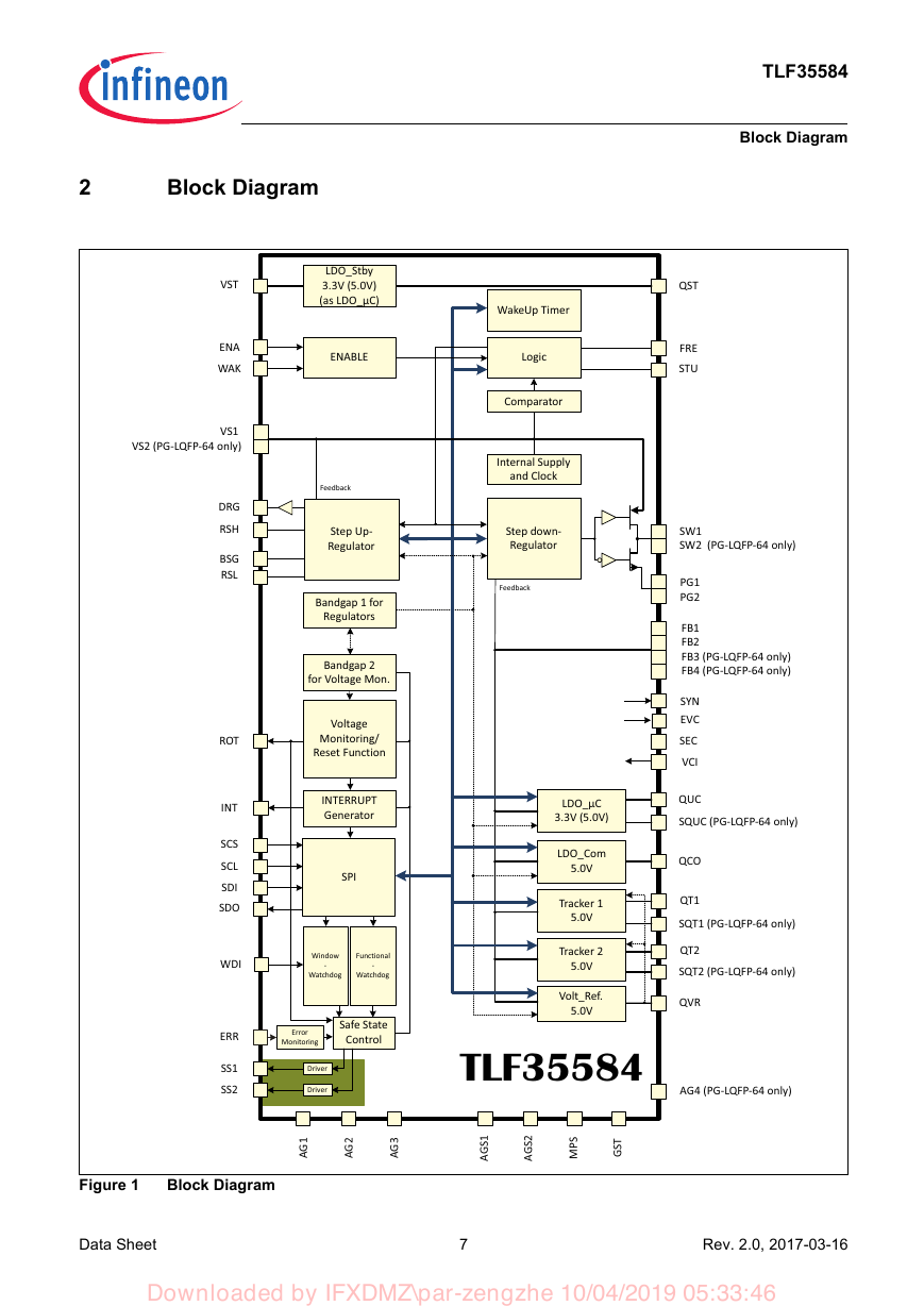
2 Block Diagram VST ENA WAK LDO_Stby 3.3V (5.0V) (as LDO_μC) ENABLE VS1 VS2 (PG-LQFP-64 only) DRG RSH BSG RSL ROT INT SCS SCL SDI SDO WDI ERR SS1 SS2 Feedback Step Up- Regulator Bandgap 1 for Regulators Bandgap 2 for Voltage Mon. Voltage Monitoring/ Reset Function INTERRUPT Generator SPI Window Functional Watchdog Watchdog - - Error Monitoring Safe State Control Driver Driver TLF35584 Block Diagram WakeUp Timer Logic Comparator Internal Supply and Clock Step down- Regulator Feedback LDO_μC 3.3V (5.0V) LDO_Com 5.0V Tracker 1 5.0V Tracker 2 5.0V Volt_Ref. 5.0V TLF35584 QST FRE STU SW1 SW2 (PG-LQFP-64 only) PG1 PG2 FB1 FB2 FB3 (PG-LQFP-64 only) FB4 (PG-LQFP-64 only) SYN EVC SEC VCI QUC SQUC (PG-LQFP-64 only) QCO QT1 SQT1 (PG-LQFP-64 only) QT2 SQT2 (PG-LQFP-64 only) QVR AG4 (PG-LQFP-64 only) Figure 1 Block Diagram 1 G A 2 G A 3 G A 1 S G A 2 S G A S P M T S G Data Sheet 7 Rev. 2.0, 2017-03-16 Downloaded by IFXDMZ\par-zengzhe 10/04/2019 05:33:46
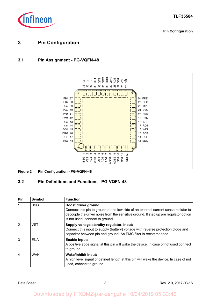
3 Pin Configuration 3.1 Pin Assignment - PG-VQFN-48 TLF35584 Pin Configuration . c . n 6 3 . c . n 5 3 . c . n 4 3 1 T Q 3 3 2 T Q 2 3 O C Q 1 3 C U Q 0 3 R V Q 9 2 3 G A 8 2 T S G 7 2 I C V 6 2 U T S 5 2 E E FB1 37 FB2 38 n.c. 39 PG2 40 PG1 41 SW1 42 n.c. 43 n.c. 44 VS1 45 DRG 46 RSH 47 RSL 48 24 FRE 23 SEC 22 MPS 21 EVC 20 ERR 19 SYN 18 INT 17 ROT 16 WDI 15 SCS 14 SCL 13 SDO E E 1 G S B 2 T S V 3 A N E 4 K A W 5 T S Q 6 1 G A 7 2 G A 8 1 S G A 9 2 S G A 0 1 2 S S 1 1 1 S S 2 1 I D S Figure 2 Pin Configuration - PG-VQFN-48 3.2 Pin 1 2 3 4 Pin Definitions and Functions - PG-VQFN-48 Symbol BSG VST ENA WAK Function Boost driver ground: Connect this pin to ground at the low side of an external current sense resistor to decouple the driver noise from the sensitive ground. If step up pre regulator option is not used, connect to ground. Supply voltage standby regulator, input: Connect this input to supply (battery) voltage with reverse protection diode and capacitor between pin and ground. An EMC filter is recommended. Enable Input: A positive edge signal at this pin will wake the device. In case of not used connect to ground. Wake/Inhibit Input: A high level signal of defined length at this pin will wake the device. In case of not used, connect to ground. Data Sheet 8 Rev. 2.0, 2017-03-16 Downloaded by IFXDMZ\par-zengzhe 10/04/2019 05:33:46
分享到:
收藏