76-81 GHz Planar Antenna
Development and Utilization for
Automotive Radar Applications
Master’s thesis in Wireless and Photonics Engineering
DAPENG WU
Department of Microtechnology and Nanoscience
CHALMERS UNIVERSITY OF TECHNOLOGY
Gothenburg, Sweden 2016
�
76-81 GHz Planar Antenna Development and Utilization for Automotive Radar
Applications
DAPENG WU
© DAPENG WU, 2016
Department of Microtechnology and Nanoscience
Chalmers University of Technology
SE-412 96 Göteborg
Sweden
Telephone + 46 (0)31-772 1000
Chalmers Reproservice
Göteborg, Sweden 2016
�
ABSTRACT
Abstract
Automotive radars are becoming more compact and affordable thanks to the rapid
development of semiconductor technology. Nowadays most vehicles are equipped with radars
to enhance safety and improve driving experiences. As an essential part of any radar sensor,
antenna will largely influence the size and cost of the whole system. Therefore, the
development of automotive radar antenna is a critically important topic of practical interest.
This thesis presents a 76.5 GHz microstrip comb-line antenna array utilized for a
commercial automotive radar prototype. First a 13-element 90 degree comb-line array is
realized in standing wave configuration so no additional reflection-cancelling structures are
required. In order to achieve a trade-off between beamwidth and sidelobe level, a 20 dB
Taylor amplitude taper is applied. Based on the conventional 90 degree array, a new array
with 45 degree polarization is built to minimize the interference from cars moving in the
opposite direction. All simulations are performed in Momentum Simulator of Advanced
Design System.
The dimensions of 90 and 45 degree comb-line arrays are 20.7×2.5 mm2 and 20.5×2.0
mm2, respectively. Both of them are implemented on Rogers RO3003 substrate. A
probe-based setup is employed for the measurement of S-parameter and radiation patterns.
From 76 to 78 GHz, both arrays exhibit consistent performance. At 76.5 GHz, the 45 degree
array yields a maximum gain of 11.35 dBi at and a sidelobe level of -16.3 dB; the
cross-polarization level is fluctuating around -10 dB. Overall, the measurement results show
good agreement with simulations.
Keywords: antenna, automotive radar, microstrip, comb-line, millimeter wave
I
�
ACKNOWLEDGMENT
Acknowledgment
It would not have been possible to complete this thesis without the generous contributions of
many great people.
First and foremost, I would like to express my sincerest gratitude to my supervisor Dr.
Ralf Reuter for his immense expertise, contagious enthusiasm and tremendous patience. The
valuable experiences I gained under his guidance will pave the way for my future career. I am
also deeply grateful to my examiner Professor Jian Yang for providing insightful advices to
improve my work and refine my thesis.
Furthermore, I am indebted to Dr. Ziqiang Tong for the helpful discussion and warm
hospitality during my stay in Germany. Special thanks go out to Dr. Heiko Gulan and Dr.
Christian Rusch for devoting enormous efforts to the antenna measurement.
Finally, I want to thank my family for the unconditional love and wholehearted support
throughout my study.
II
�
TABLE OF CONTENTS
Table of Contents
Abstract ........................................................................................................................................... I
Acknowledgment ......................................................................................................................... II
List of Abbreviations .................................................................................................................. IV
1 Introduction ................................................................................................................................. 1
1.1 Overview of Automotive Radar System .......................................................................... 1
1.2 Antennas for Automotive Radars ..................................................................................... 3
1.3 Aim of the Thesis Project .................................................................................................. 4
2 Analysis of Microstrip Comb-Line Antenna Array ............................................................... 7
2.1 Characteristics of Microstrip Open-Circuit Stub as a Radiating Element ..................... 7
2.1.1 Radiation Pattern of a Microstrip Open-Circuit Stub .......................................... 7
2.1.2 Impact of Substrate Surface Waves ....................................................................... 9
2.1.3 Improved Analysis of Microstrip Open-Circuit Stub ......................................... 11
2.1.4 End Admittance of Microstrip Open-Circuit Stub .............................................13
2.2 Comb-Line Antenna Array with Microstrip Open-Circuit Stubs .................................14
2.2.1 Microstrip Open-Circuit Stub as an Array Element ...........................................15
2.2.2 Comparison of Traveling Wave Array and Standing Wave Array.....................17
3 Designs of 90 and 45 Degree Standing Wave Microstrip Comb-Line Antenna Arrays.19
3.1 90 Degree Uniform Comb-Line Antenna Array ............................................................19
3.2 90 Degree Amplitude Tapered Comb-Line Antenna Array ..........................................22
3.3 45 Degree Amplitude Tapered Comb-Line Antenna Array ..........................................26
4 Measurements of 90 and 45 Degree Standing Wave Microstrip Comb-Line Antenna
Arrays ............................................................................................................................................29
4.1 Probe-Based Antenna Measurement Setup ....................................................................29
4.2 Measurement Results of 90 and 45 Degree Comb-Line Antenna Arrays ....................31
4.2.1 90 Degree Amplitude Tapered Comb-Line Aray ................................................31
4.2.2 45 Degree Amplitude Tapered Comb-Line Aray ................................................34
5 Conclusion .................................................................................................................................37
References .....................................................................................................................................39
III
�
LIST OF ABBREVIATIONS
List of Abbreviations
ACC
ADS
AiP
AoC
AUT
CAD
Adaptive Cruise Control
Advanced Design System
Antenna in Package
Antenna on Chip
Antenna Under Test
Computer-Aided Design
CMOS
Complementary Metal-Oxide-Semiconductor
CST
CTA
EMI
eWLB
FMCW
GaAs
GSG
HFSS
HPBW
LRR
MRR
RCP
SiGe
SOL
SRR
TEM
Computer Simulation Technology
Cross Traffic Alert
Electromagnetic Interference
Embedded Wafer Level Ball Grid Array
Frequency-Modulated Continuous-Wave
Gallium Arsenide
Ground-Signal-Ground
High Frequency Structural Simulator
Half-Power Beamwidth
Lang Range Radar
Medium Range Radar
Redistributed Chip Package
Silicon-Germanium
Short-Open-Load
Short Range Radar
Transverse Electromagnetic
IV
�
CHAPTER 1 INTRODUCTION
1 Introduction
In 1904, the German inventor Christian Hülsmeyer built a device for the detection of ships in
fog, which is commonly referred to as the first radar system. During World War Ⅱ, radar was
put into practice and under a rapid development. Nowadays, radar is also widely used in civil
areas and one of the most important applications is the automotive radar system.
1.1 Overview of Automotive Radar System
As early as 1964 the use of radar system on vehicles for the prevention of collisions has been
discussed [1]. In the 1970s some automotive radar prototypes were built and road tested
[2]-[4]. However, at that time the high cost and large dimensions of key components were the
limiting factors for commercial application. It was not until the 1990s that major automobile
manufacturers and suppliers started the research on automotive radar again. Since 1992 a 24
GHz Doppler radar system developed by Eaton VORAD Technologies has been installed in
1700 Greyhound buses and it helped to reduce the accident rate by 25% [5]. In the late 90s
Mercedes-Benz firstly introduced the 77GHz-radar-based DISTRONIC system [6] and other
manufacturers soon followed with their own products. Today most high and middle class
vehicles are equipped with radar sensors and it is safe to predict that it will be more widely
available and affordable in the near future.
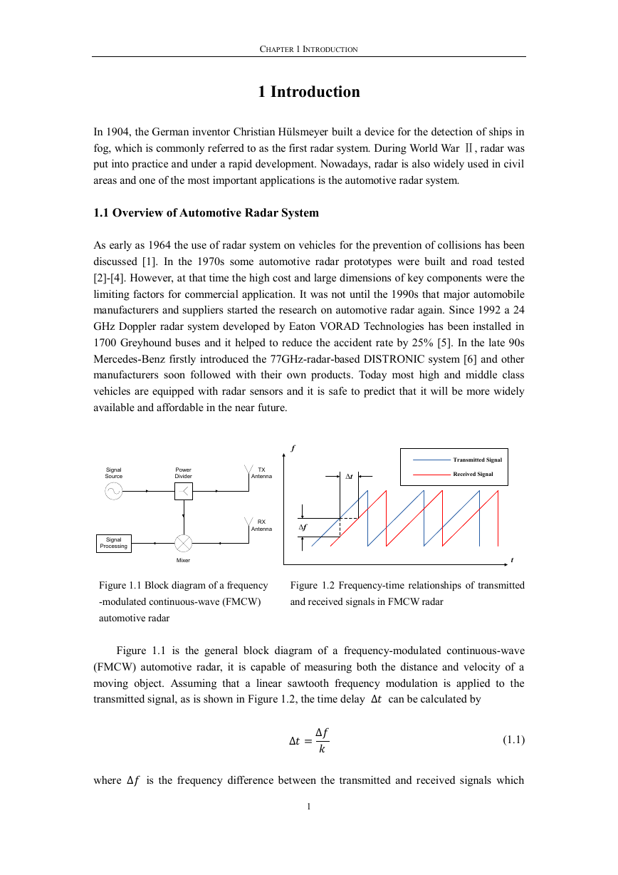
Figure 1.1 Block diagram of a frequency
Figure 1.2 Frequency-time relationships of transmitted
-modulated continuous-wave (FMCW)
and received signals in FMCW radar
automotive radar
Figure 1.1 is the general block diagram of a frequency-modulated continuous-wave
(FMCW) automotive radar, it is capable of measuring both the distance and velocity of a
moving object. Assuming that a linear sawtooth frequency modulation is applied to the
transmitted signal, as is shown in Figure 1.2, the time delay can be calculated by
(1.1)
where is the frequency difference between the transmitted and received signals which
1
SignalSourcePowerDividerSignalProcessingMixerTXAntennaRXAntennaft∆t∆f Transmitted Signal Received Signal�
76-81 GHZ PLANAR ANTENNA DEVELOPMENT AND UTILIZATION FOR RADAR APPLICATIONS
could be measured from the mixer output and is the frequency sweep rate.
The distance between the observer and target is then given by
(1.2)
Here is the speed of light in air and a factor of is introduced to get the one-way
distance.
Two different frequency bands are available for automotive radar applications: 24 GHz
and 77- GHz. The 77 GHz solution offers advantages such as smaller dimension and broader
bandwidth, but also faces more challenges in design and implementation. The 77 GHz band
could be divided into two subbands: 76-77 GHz and 77-81 GHz (also called 79 GHz band).
The former has been approved by most countries, while the latter is only available in Europe
so far but has been under discussion in other countries.
The functions of automotive radar sensors vary with their maximum ranges. Long range
radar (LRR) has a narrow beam and it is usually mounted in the front grill to measure the
distance of objects ahead (up to 250 m); short range radar (SRR) offers a broader beam and
can be used to monitor the vicinity of a vehicle (within 30 m); between LRR and SRR, there
is medium range radar (MRR) which can be installed on the front, the rear, or the side area for
different applications. Detailed comparisons of the three sensor types are given in Table 1.1.
Table 1.1 Automotive radar classifications
LRR
MRR
SRR
Maximum Range (m)
Applications
150-250
60-150
30
Adaptive cruise control (ACC)
Cross traffic alert (CTA), ACC
Blind spot detection, parking aid
The first generation of commercial automotive radar in 77 GHz was implemented in
gallium arsenide (GaAs) technology [7]. Despite their excellent performance, the market
share of GaAs-based products is limited by the high fabrication cost. Nowadays, most
automotive radar sensors are based on silicon-germanium (SiGe) technology since it is a more
cost-effective solution. As one of the main automotive semiconductor suppliers, Freescale
presented its own transceiver chipset using SiGe BiCMOS technology in 2012 [8]. It
consisted of a four-channel receiver and a single-channel transmitter, which covered the
whole frequency range of 76-81 GHz and could be used for both LRR and SRR. Besides
on-wafer measurement, the chips were also tested in redistributed chip package (RCP) and the
results showed great potential for commercial applications.
In 2009, Fujitsu Laboratories reported the first 77 GHz automotive radar transceiver chip
in 90 nm CMOS technology [9]; one year later, researchers from National Taiwan University
published a fully integrated 77 GHz FMCW radar system in 65 nm CMOS technology [10].
The advantages of CMOS technology are the lower cost and power consumption, however,
the current performances of CMOS radars are not yet comparable with their SiGe
counterparts. Therefore, there is still a long way to go for CMOS automotive radars to
2
�



 2023年江西萍乡中考道德与法治真题及答案.doc
 2012年重庆南川中考生物真题及答案.doc
 2013年江西师范大学地理学综合及文艺理论基础考研真题.doc
 2020年四川甘孜小升初语文真题及答案I卷.doc
 2020年注册岩土工程师专业基础考试真题及答案.doc
 2023-2024学年福建省厦门市九年级上学期数学月考试题及答案.doc
 2021-2022学年辽宁省沈阳市大东区九年级上学期语文期末试题及答案.doc
 2022-2023学年北京东城区初三第一学期物理期末试卷及答案.doc
 2018上半年江西教师资格初中地理学科知识与教学能力真题及答案.doc
 2012年河北国家公务员申论考试真题及答案-省级.doc
 2020-2021学年江苏省扬州市江都区邵樊片九年级上学期数学第一次质量检测试题及答案.doc
 2022下半年黑龙江教师资格证中学综合素质真题及答案.doc