Cover
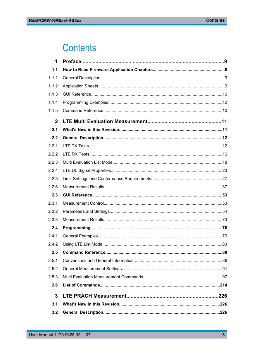
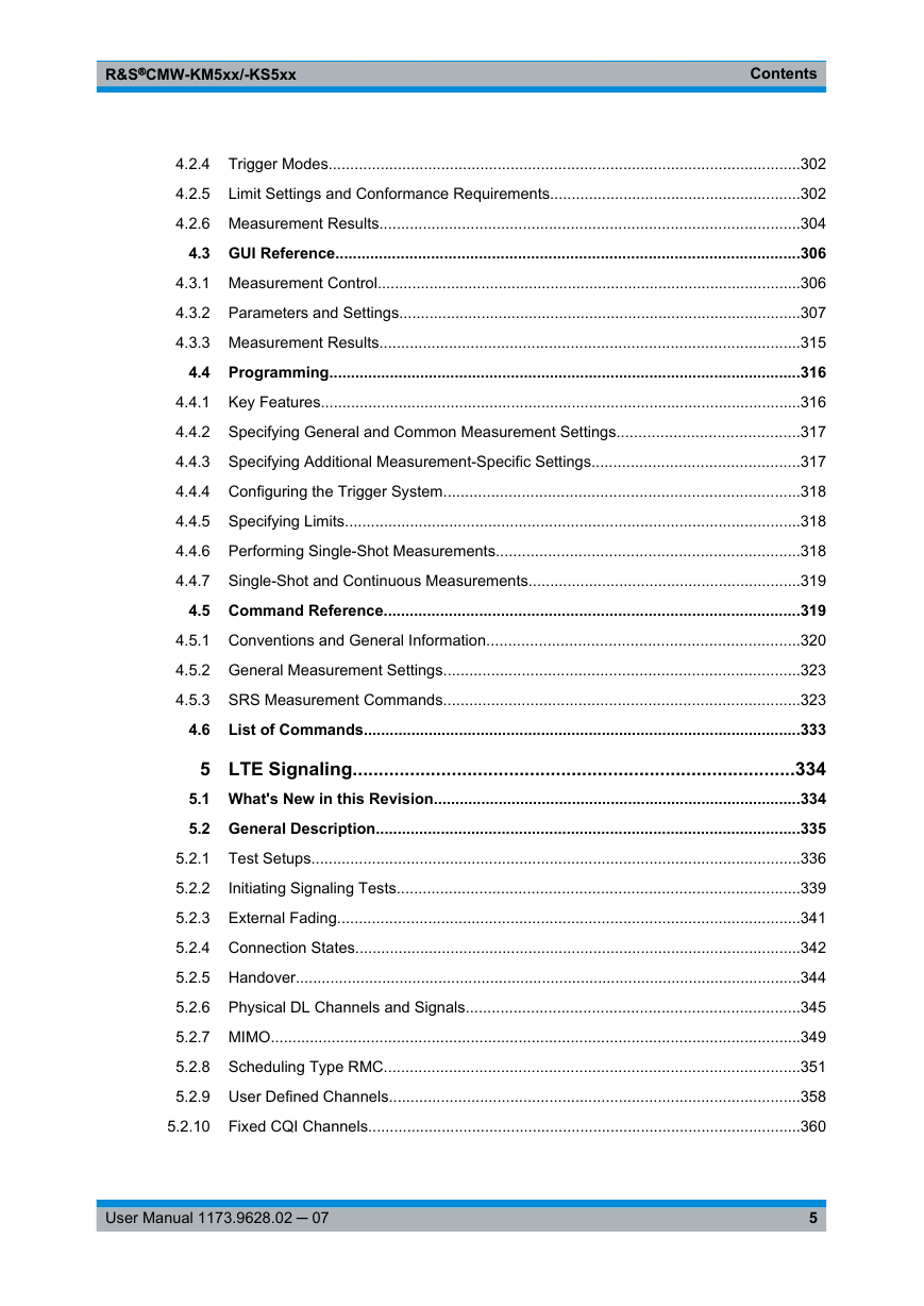
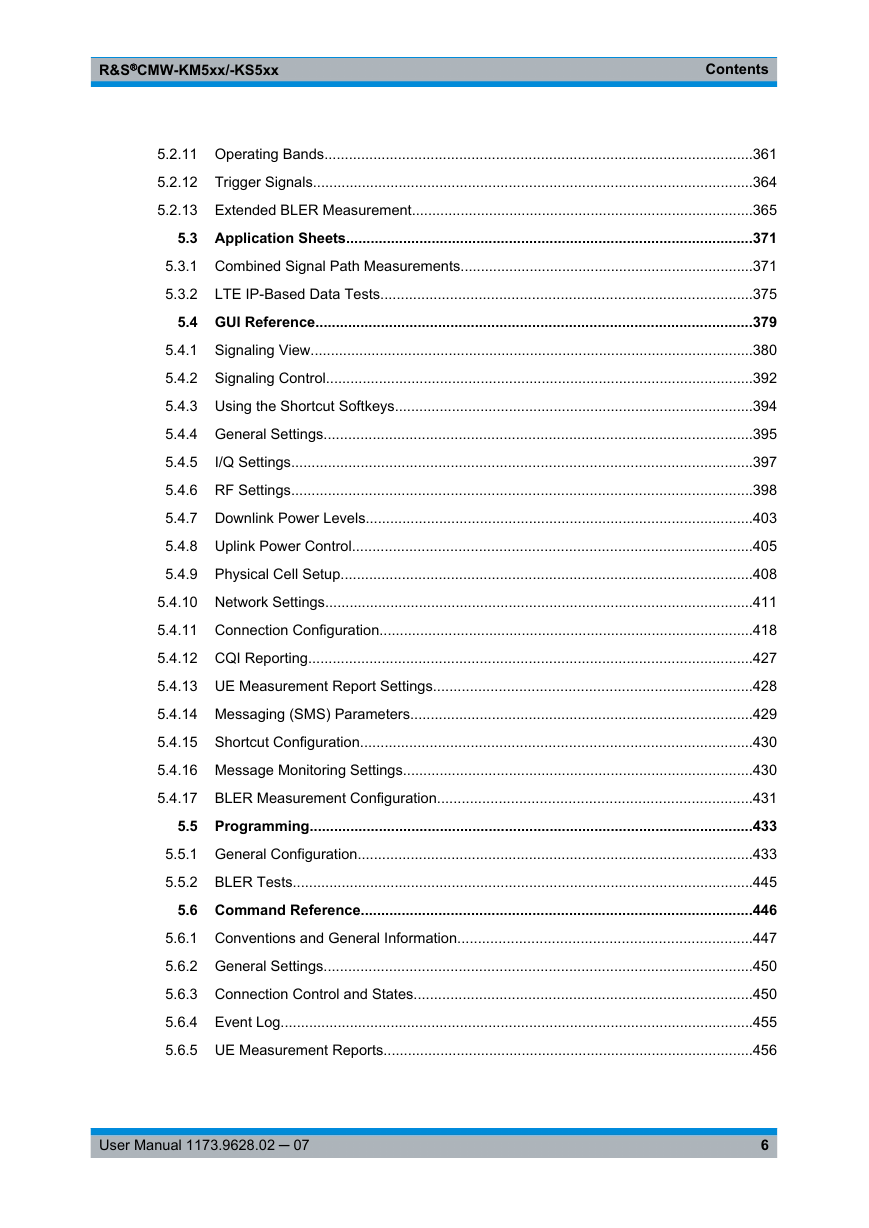
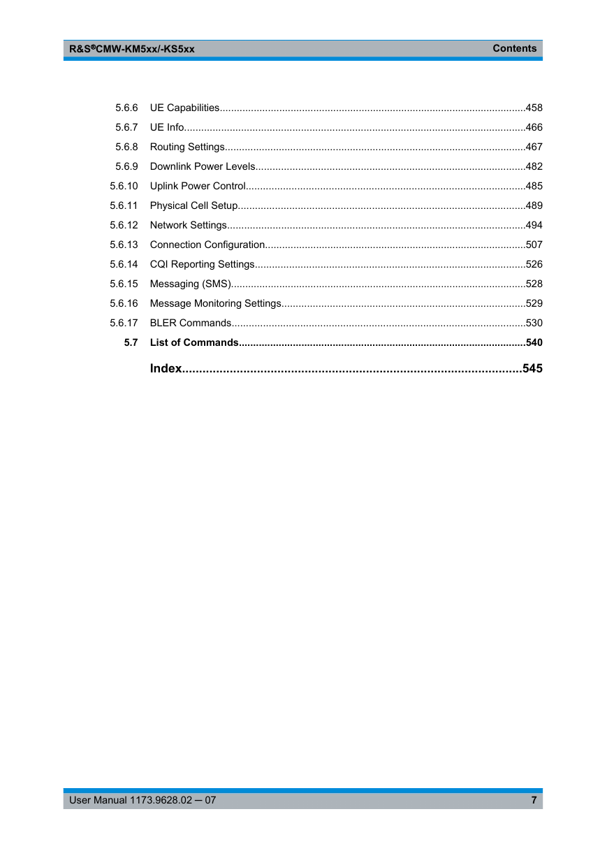
Contents
1 Preface
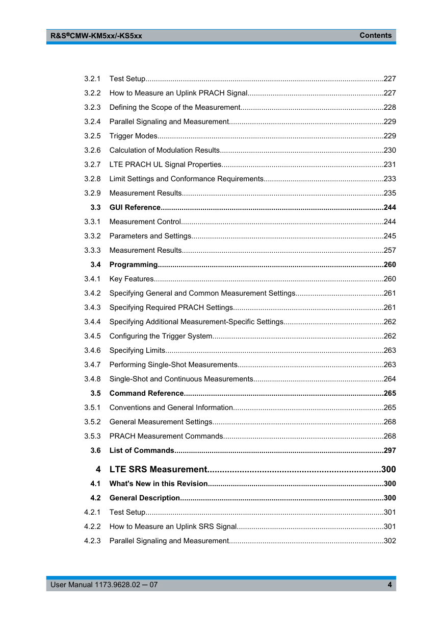
1.1 How to Read Firmware Application Chapters
1.1.1 General Description
1.1.2 Application Sheets
1.1.3 GUI Reference
1.1.4 Programming Examples
1.1.5 Command Reference
2 LTE Multi Evaluation Measurement
2.1 What's New in this Revision
2.2 General Description
2.2.1 LTE TX Tests
2.2.1.1 Test Setup
2.2.1.2 How to Measure an Uplink LTE Signal
2.2.1.3 Defining the Scope of the Measurement
2.2.1.4 Parallel Signaling and Measurement
2.2.1.5 Trigger Modes
2.2.1.6 Calculation of Modulation Results
2.2.2 LTE RX Tests
2.2.2.1 Test Setup
2.2.2.2 Performing an LTE RX Measurement
2.2.3 Multi Evaluation List Mode
2.2.3.1 List Mode Configuration
2.2.3.2 Offline Mode and Offline Segment
2.2.4 LTE UL Signal Properties
2.2.4.1 Resources in Time and Frequency Domain
2.2.4.2 Frequency Bands
2.2.5 Limit Settings and Conformance Requirements
2.2.5.1 Transmit Modulation Limits
2.2.5.2 Frequency Error Limits
2.2.5.3 I/Q Origin Offset Limits
2.2.5.4 Inband Emissions Limits
2.2.5.5 Equalizer Spectrum Flatness Limits
2.2.5.6 Occupied Bandwidth Limits
2.2.5.7 Spectrum Emission Mask
2.2.5.8 ACLR Limits
2.2.5.9 Power Dynamics Limits
2.2.6 Measurement Results
2.2.6.1 Overview
2.2.6.2 Detailed Views: EVM, Magnitude Error, Phase Error
2.2.6.3 Detailed Views: Inband Emissions
2.2.6.4 Detailed Views: Equalizer Spectrum Flatness
2.2.6.5 Detailed Views: Spectrum Emission Mask
2.2.6.6 Detailed Views: Spectrum ACLR
2.2.6.7 Detailed Views: I/Q Constellation Diagram
2.2.6.8 Detailed Views: RB Allocation Table
2.2.6.9 Detailed Views: Power Monitor
2.2.6.10 Detailed Views: Power Dynamics
2.2.6.11 Detailed Views: TX Measurement and BLER
2.2.6.12 Selecting and Modifying Views
2.2.6.13 Using Markers
2.2.6.14 Common View Elements
2.3 GUI Reference
2.3.1 Measurement Control
2.3.2 Parameters and Settings
2.3.2.1 Signal Routing and Analyzer Settings
2.3.2.2 Measurement Control Settings
2.3.2.3 Modulation Settings
2.3.2.4 Spectrum Settings
2.3.2.5 Trigger Settings
2.3.2.6 Limit Settings
2.3.2.7 Additional Softkeys and Hotkeys
2.3.3 Measurement Results
2.4 Programming
2.4.1 General Examples
2.4.1.1 Specifying General and Common Measurement Settings
2.4.1.2 Specifying Required Settings
2.4.1.3 Specifying Additional Measurement-Specific Settings
2.4.1.4 Configuring the Trigger System
2.4.1.5 Specifying Limits
2.4.1.6 Performing Single-Shot Measurements
2.4.1.7 Single-Shot and Continuous Measurements
2.4.2 Using LTE List Mode
2.4.2.1 Specify Global Measurement Settings
2.4.2.2 Specifying List Mode Settings
2.4.2.3 Performing Single-Shot Measurements
2.4.2.4 Retrieving Single Results for All Segments
2.5 Command Reference
2.5.1 Conventions and General Information
2.5.1.1 MEAS
2.5.1.2 FETCh, READ and CALCulate Commands
2.5.1.3 Current and Statistical Results
2.5.1.4 Reliability Indicator
2.5.2 General Measurement Settings
2.5.2.1 Duplex Mode
2.5.2.2 Signal Routing
2.5.2.3 Analyzer Settings
2.5.2.4 Common Measurement Control Settings
2.5.3 Multi Evaluation Measurement Commands
2.5.3.1 Measurement Control and States
2.5.3.2 Enabling Results and Views
2.5.3.3 Measurement Parameters - General Part
2.5.3.4 Modulation Measurement Settings
2.5.3.5 Spectrum Measurement Settings
2.5.3.6 Power Measurement Settings
2.5.3.7 BLER Measurement Settings
2.5.3.8 List Mode Settings
2.5.3.9 Trigger Settings
2.5.3.10 Limits (Modulation, QPSK)
2.5.3.11 Limits (Modulation, 16-QAM / 64-QAM)
2.5.3.12 Limits (Spectrum)
2.5.3.13 Limits (Power)
2.5.3.14 Detected Signal Configuration
2.5.3.15 EVM Results (Traces)
2.5.3.16 Magnitude Error Results (Traces)
2.5.3.17 Phase Error Results (Traces)
2.5.3.18 Equalizer Spectrum Flatness Results (Traces)
2.5.3.19 Spectrum Emission Results (Traces)
2.5.3.20 I/Q Constellation Results (Traces)
2.5.3.21 Power Dynamics Results (Traces)
2.5.3.22 Inband Emission Results
2.5.3.23 ACLR Spectrum Results
2.5.3.24 RB Allocation Table Results
2.5.3.25 Power Monitor Results
2.5.3.26 Modulation Results (Single Values)
2.5.3.27 Equalizer Spectrum Flatness Results (Single Values)
2.5.3.28 Power Dynamics Results (Single Values)
2.5.3.29 Spectrum Emission Results (Single Values)
2.5.3.30 BLER Results
2.5.3.31 List Mode Results (One Segment)
2.5.3.32 List Mode Results (All Segments, One Result)
2.6 List of Commands
3 LTE PRACH Measurement
3.1 What's New in this Revision
3.2 General Description
3.2.1 Test Setup
3.2.2 How to Measure an Uplink PRACH Signal
3.2.3 Defining the Scope of the Measurement
3.2.4 Parallel Signaling and Measurement
3.2.5 Trigger Modes
3.2.6 Calculation of Modulation Results
3.2.7 LTE PRACH UL Signal Properties
3.2.7.1 Preambles in the Frequency Domain
3.2.7.2 Preambles in the Time Domain
3.2.7.3 Preamble Sequences
3.2.8 Limit Settings and Conformance Requirements
3.2.8.1 Transmit Modulation Limits
3.2.8.2 Power Dynamics Limits
3.2.9 Measurement Results
3.2.9.1 Overview
3.2.9.2 Detailed Views: EVM, Magnitude Error, Phase Error
3.2.9.3 Detailed Views: EVM vs Preamble, Power vs Preamble
3.2.9.4 Detailed Views: I/Q Constellation Diagram
3.2.9.5 Detailed Views: Power Dynamics
3.2.9.6 Detailed Views: TX Measurement
3.2.9.7 Selecting and Modifying Views
3.2.9.8 Using Markers
3.2.9.9 Common View Elements
3.3 GUI Reference
3.3.1 Measurement Control
3.3.2 Parameters and Settings
3.3.2.1 Signal Routing and Analyzer Settings
3.3.2.2 Measurement Control Settings
3.3.2.3 Modulation Settings
3.3.2.4 Power Settings
3.3.2.5 Trigger Settings
3.3.2.6 Limit Settings
3.3.2.7 Additional Softkeys and Hotkeys
3.3.3 Measurement Results
3.4 Programming
3.4.1 Key Features
3.4.2 Specifying General and Common Measurement Settings
3.4.3 Specifying Required PRACH Settings
3.4.4 Specifying Additional Measurement-Specific Settings
3.4.5 Configuring the Trigger System
3.4.6 Specifying Limits
3.4.7 Performing Single-Shot Measurements
3.4.8 Single-Shot and Continuous Measurements
3.5 Command Reference
3.5.1 Conventions and General Information
3.5.1.1 MEAS
3.5.1.2 FETCh, READ and CALCulate Commands
3.5.1.3 Current and Statistical Results
3.5.1.4 Reliability Indicator
3.5.2 General Measurement Settings
3.5.3 PRACH Measurement Commands
3.5.3.1 Measurement Control and States
3.5.3.2 Enabling Results and Views
3.5.3.3 Measurement Parameters - General Part
3.5.3.4 Modulation Measurement Settings
3.5.3.5 Power Measurement Settings
3.5.3.6 Trigger Settings
3.5.3.7 Limits (Modulation)
3.5.3.8 Limits (Power)
3.5.3.9 Detected Signal Configuration
3.5.3.10 EVM vs. Subcarrier Results (Traces)
3.5.3.11 Magnitude Error Results (Traces)
3.5.3.12 Phase Error Results (Traces)
3.5.3.13 EVM vs. Preamble Results (Traces)
3.5.3.14 Power vs. Preamble Results (Traces)
3.5.3.15 I/Q Constellation Results (Traces)
3.5.3.16 Power Dynamics Results (Traces)
3.5.3.17 "TX Measurement" Results (Single Values)
3.5.3.18 EVM / Power vs. Preamble Results (Single Values)
3.5.3.19 Power Dynamics Results (Single Values)
3.6 List of Commands
4 LTE SRS Measurement
4.1 What's New in this Revision
4.2 General Description
4.2.1 Test Setup
4.2.2 How to Measure an Uplink SRS Signal
4.2.3 Parallel Signaling and Measurement
4.2.4 Trigger Modes
4.2.5 Limit Settings and Conformance Requirements
4.2.5.1 Power Dynamics Limits
4.2.6 Measurement Results
4.2.6.1 Modifying Views
4.2.6.2 Using Markers
4.3 GUI Reference
4.3.1 Measurement Control
4.3.2 Parameters and Settings
4.3.2.1 Signal Routing and Analyzer Settings
4.3.2.2 Measurement Control Settings
4.3.2.3 Trigger Settings
4.3.2.4 Limit Settings
4.3.2.5 Additional Softkeys and Hotkeys
4.3.3 Measurement Results
4.4 Programming
4.4.1 Key Features
4.4.2 Specifying General and Common Measurement Settings
4.4.3 Specifying Additional Measurement-Specific Settings
4.4.4 Configuring the Trigger System
4.4.5 Specifying Limits
4.4.6 Performing Single-Shot Measurements
4.4.7 Single-Shot and Continuous Measurements
4.5 Command Reference
4.5.1 Conventions and General Information
4.5.1.1 MEAS
4.5.1.2 FETCh, READ and CALCulate Commands
4.5.1.3 Current and Statistical Results
4.5.1.4 Reliability Indicator
4.5.2 General Measurement Settings
4.5.3 SRS Measurement Commands
4.5.3.1 Measurement Control and States
4.5.3.2 Measurement Parameters
4.5.3.3 Trigger Settings
4.5.3.4 Limits
4.5.3.5 Power Dynamics Results (Traces)
4.5.3.6 Power Dynamics Results (Single Values)
4.6 List of Commands
5 LTE Signaling
5.1 What's New in this Revision
5.2 General Description
5.2.1 Test Setups
5.2.1.1 Test setup for Scenario Two RF Out Ports
5.2.1.2 Test Setup for Scenario IQ out - RF in
5.2.1.3 Test Setups with External Fading
5.2.2 Initiating Signaling Tests
5.2.3 External Fading
5.2.4 Connection States
5.2.5 Handover
5.2.6 Physical DL Channels and Signals
5.2.6.1 Resources in Time and Frequency Domain
5.2.6.2 Physical Channel Overview
5.2.6.3 Physical Signal Overview
5.2.7 MIMO
5.2.7.1 Radio Channel Coefficients for MIMO 2x2
5.2.8 Scheduling Type RMC
5.2.8.1 UL RMCs
5.2.8.2 DL RMCs, One TX Antenna
5.2.8.3 DL RMCs, Multiple TX Antennas
5.2.9 User Defined Channels
5.2.9.1 Supported Number of RB / Position of First RB (DL)
5.2.9.2 Supported Number of RB / Position of First RB (UL)
5.2.9.3 Supported Transport Block Size Indices
5.2.10 Fixed CQI Channels
5.2.11 Operating Bands
5.2.12 Trigger Signals
5.2.13 Extended BLER Measurement
5.2.13.1 Performing a Measurement
5.2.13.2 Result Overview
5.2.13.3 Detailed View: BLER
5.2.13.4 Detailed View: Throughput
5.2.13.5 Detailed View: CQI Reporting
5.2.13.6 Common View Elements
5.2.13.7 Selecting and Modifying Views
5.2.13.8 Using Markers
5.3 Application Sheets
5.3.1 Combined Signal Path Measurements
5.3.1.1 Options and Equipment Required
5.3.1.2 Setting up a Connection
5.3.1.3 Analyzing the UL Signal from the UE
5.3.1.4 Possible Extensions
5.3.1.5 SRS and PRACH Measurements
5.3.2 LTE IP-Based Data Tests
5.3.2.1 Options and Equipment Required
5.3.2.2 Preparing the Tests
5.3.2.3 Measuring the Latency with Ping
5.3.2.4 Measuring the Throughput with IPerf
5.3.2.5 Possible Extensions
5.4 GUI Reference
5.4.1 Signaling View
5.4.1.1 Connection Status
5.4.1.2 Event Log
5.4.1.3 UE Measurement Report
5.4.1.4 UE Capabilities
General UE Capability Information
PDCP UE Capabilities
Physical Layer UE Capabilities
RF UE Capabilities
Measurement UE Capabilities
Feature Group UE Capabilities
Inter RAT UE Capabilities
5.4.1.5 UE Info
5.4.1.6 Settings
5.4.1.7 TTI Based Channel Configuration
5.4.2 Signaling Control
5.4.3 Using the Shortcut Softkeys
5.4.4 General Settings
5.4.5 I/Q Settings
5.4.6 RF Settings
5.4.6.1 RF Signal Routing
5.4.6.2 RF Frequency
5.4.6.3 Expected Uplink Power
5.4.7 Downlink Power Levels
5.4.8 Uplink Power Control
5.4.9 Physical Cell Setup
5.4.10 Network Settings
5.4.10.1 Neighbor Cell Settings
5.4.10.2 Cell Reselection
5.4.10.3 Identity Settings
5.4.10.4 Security Settings
5.4.10.5 UE Identity
5.4.10.6 Timer and Constants
5.4.11 Connection Configuration
5.4.11.1 Miscellaneous Connection Configuration Settings
5.4.11.2 Transmission Scheme Settings
5.4.11.3 RMC Connection Settings
5.4.11.4 User Defined Channel Configurations
5.4.12 CQI Reporting
5.4.13 UE Measurement Report Settings
5.4.14 Messaging (SMS) Parameters
5.4.15 Shortcut Configuration
5.4.16 Message Monitoring Settings
5.4.17 BLER Measurement Configuration
5.4.17.1 Measurement Control
5.4.17.2 Measurement Views
5.4.17.3 Settings
5.5 Programming
5.5.1 General Configuration
5.5.1.1 Specifying General Settings
5.5.1.2 Configuring DL Power Levels
5.5.1.3 Configuring UL Power Control for Call Setup
5.5.1.4 Configuring Physical Cell Setup
5.5.1.5 Configuring Network Settings
5.5.1.6 Configuring Connection Settings
5.5.1.7 Configuring CQI Reporting
5.5.1.8 Configuring Measurement Reports
5.5.1.9 Configuring Message Monitoring
5.5.1.10 Switching on the Cell Signal and the UE
5.5.1.11 Configuring the I/Q Settings
5.5.1.12 Setting up a Connection
5.5.1.13 Query Information Provided by the UE
5.5.1.14 Performing an Intra RAT Handover
5.5.1.15 Performing an Inter RAT Handover
5.5.1.16 Sending / Receiving a Short Message
5.5.1.17 Modifying Parameters for an Established Connection
5.5.2 BLER Tests
5.5.2.1 Configuring the BLER Measurement
5.5.2.2 Performing a BLER Measurement
5.6 Command Reference
5.6.1 Conventions and General Information
5.6.1.1 SIGN
5.6.1.2 Reliability Indicator
5.6.2 General Settings
5.6.3 Connection Control and States
5.6.4 Event Log
5.6.5 UE Measurement Reports
5.6.6 UE Capabilities
5.6.7 UE Info
5.6.8 Routing Settings
5.6.8.1 Signal Routing
5.6.8.2 Signal Settings
5.6.9 Downlink Power Levels
5.6.10 Uplink Power Control
5.6.11 Physical Cell Setup
5.6.12 Network Settings
5.6.12.1 Neighbor Cell Settings
5.6.12.2 Cell Reselection Settings
5.6.12.3 Identity Settings
5.6.12.4 Security Settings
5.6.12.5 UE Identity
5.6.12.6 Timer and Constants
5.6.13 Connection Configuration
5.6.13.1 General Connection Settings
5.6.13.2 Scheduling Type Specific Settings
5.6.14 CQI Reporting Settings
5.6.15 Messaging (SMS)
5.6.16 Message Monitoring Settings
5.6.17 BLER Commands
5.7 List of Commands
Index


 2023年江西萍乡中考道德与法治真题及答案.doc
 2012年重庆南川中考生物真题及答案.doc
 2013年江西师范大学地理学综合及文艺理论基础考研真题.doc
 2020年四川甘孜小升初语文真题及答案I卷.doc
 2020年注册岩土工程师专业基础考试真题及答案.doc
 2023-2024学年福建省厦门市九年级上学期数学月考试题及答案.doc
 2021-2022学年辽宁省沈阳市大东区九年级上学期语文期末试题及答案.doc
 2022-2023学年北京东城区初三第一学期物理期末试卷及答案.doc
 2018上半年江西教师资格初中地理学科知识与教学能力真题及答案.doc
 2012年河北国家公务员申论考试真题及答案-省级.doc
 2020-2021学年江苏省扬州市江都区邵樊片九年级上学期数学第一次质量检测试题及答案.doc
 2022下半年黑龙江教师资格证中学综合素质真题及答案.doc