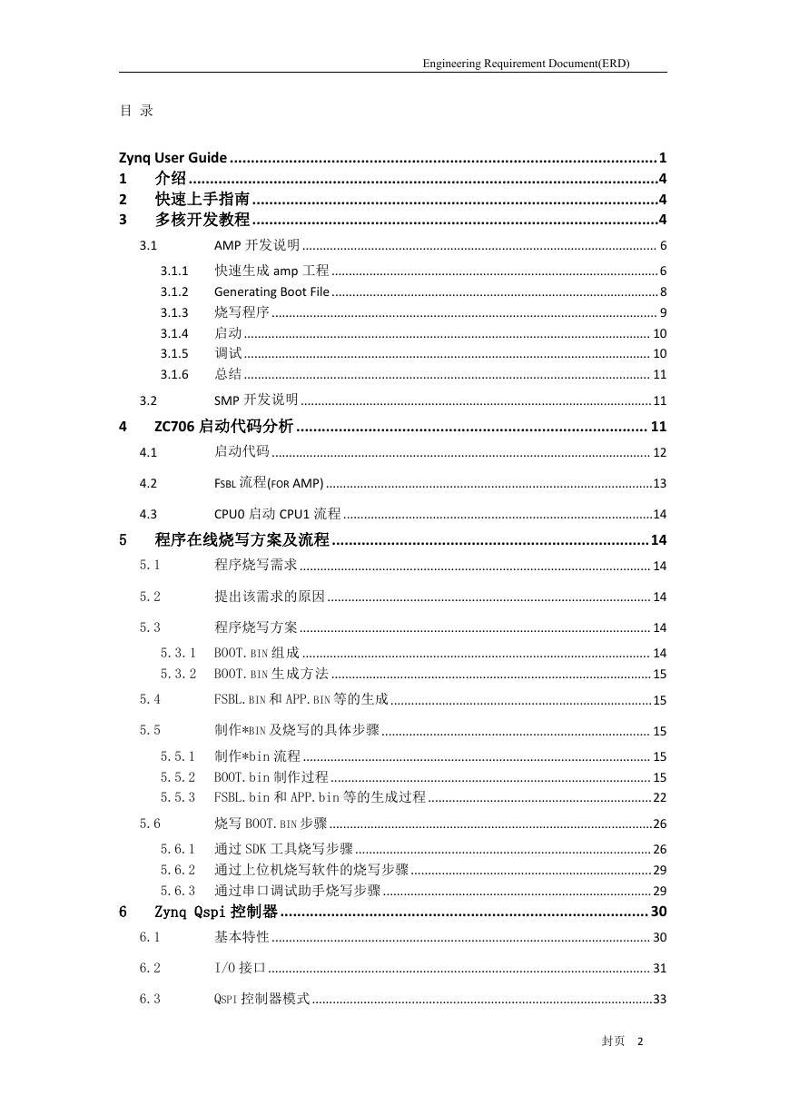
Zynq User Guide
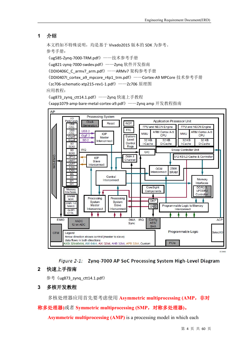
1介绍
2快速上手指南
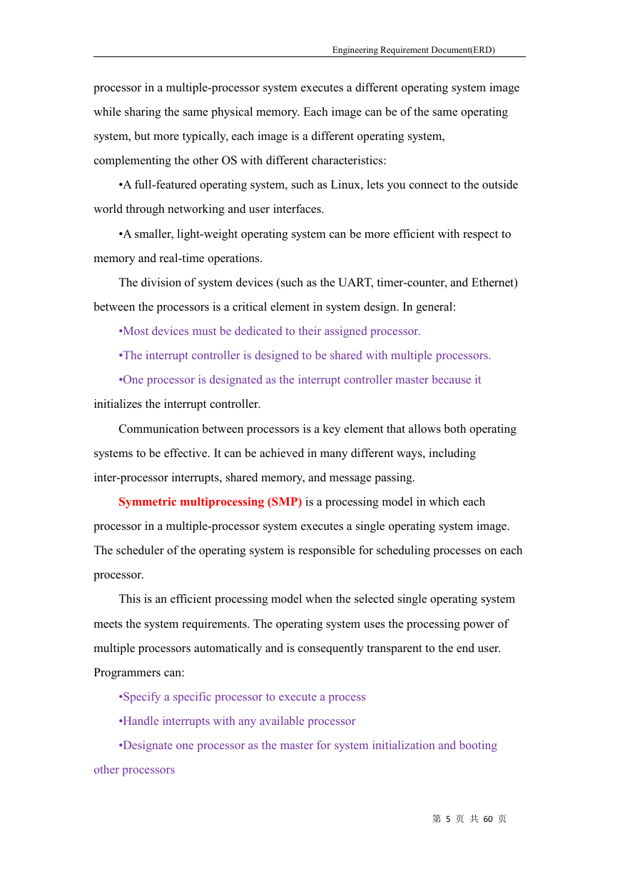
3多核开发教程
3.1AMP开发说明
3.1.1快速生成amp工程
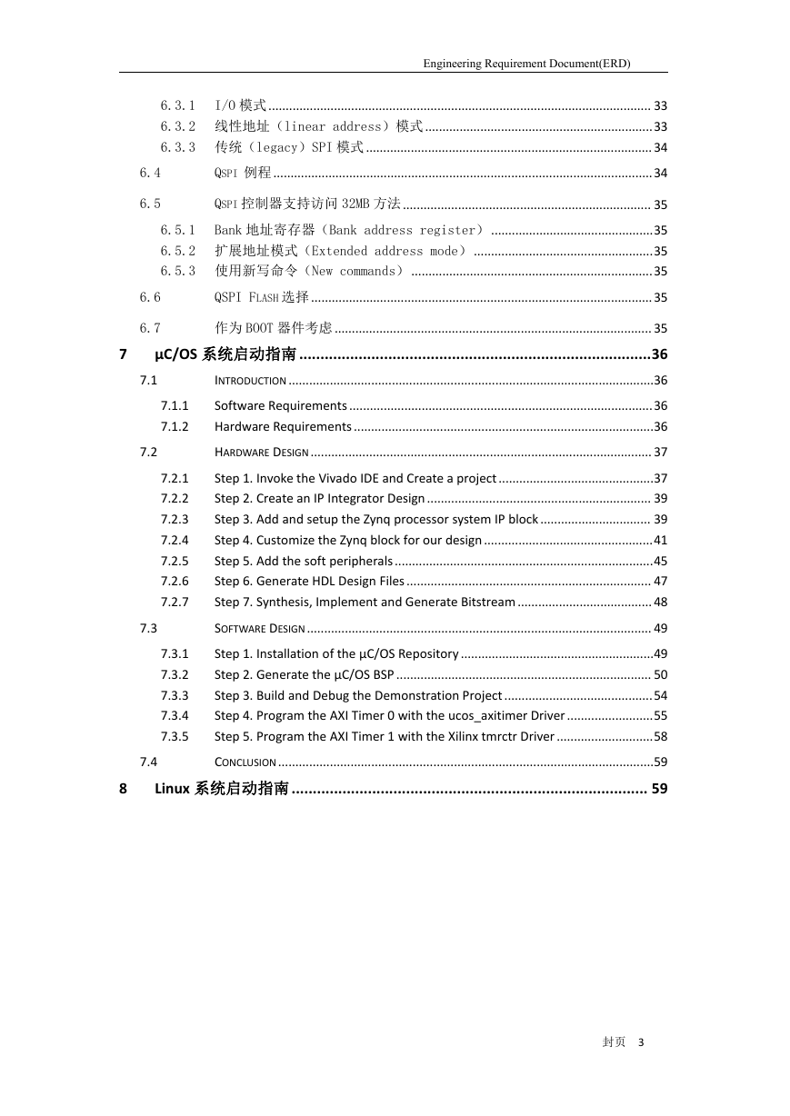
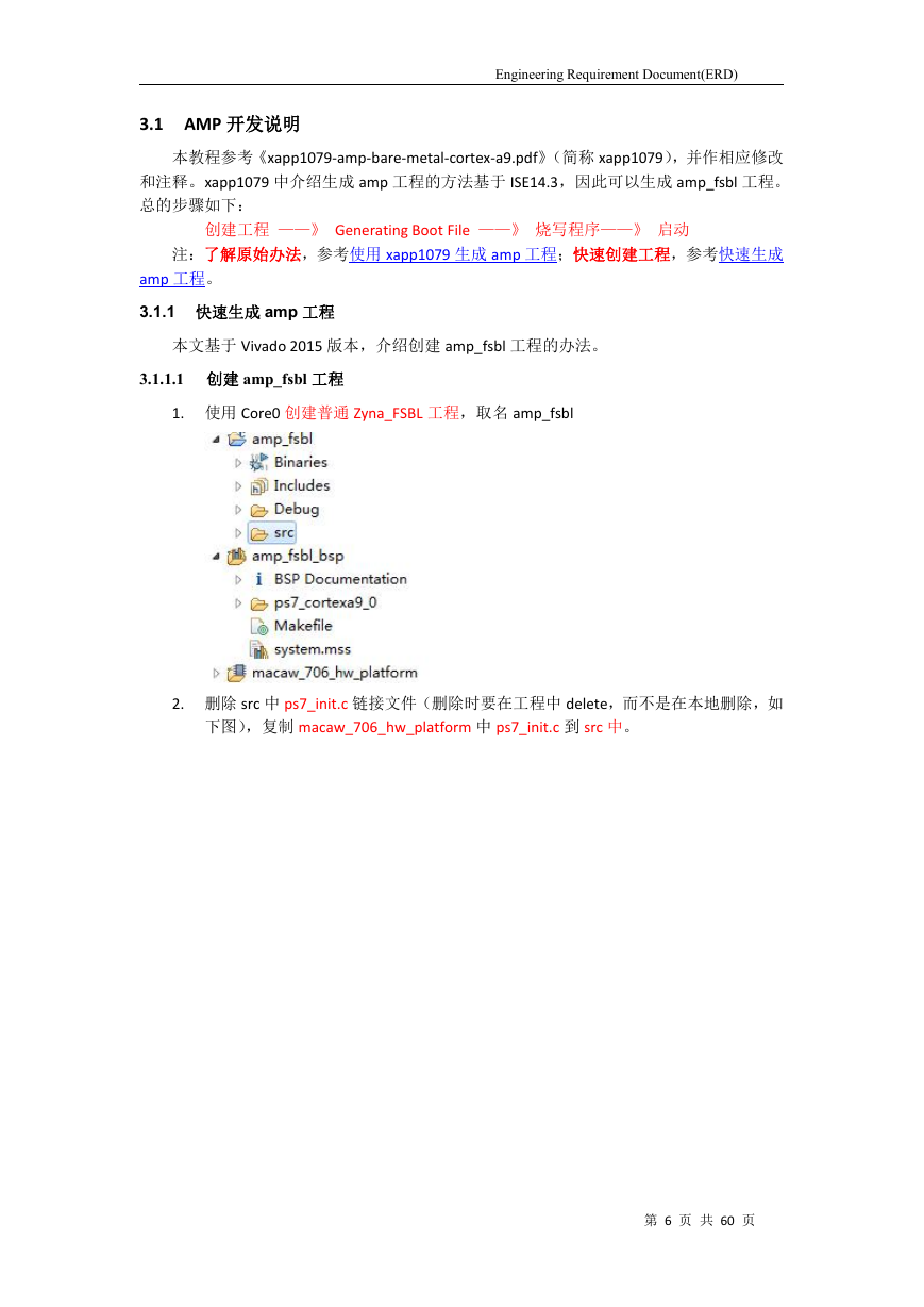
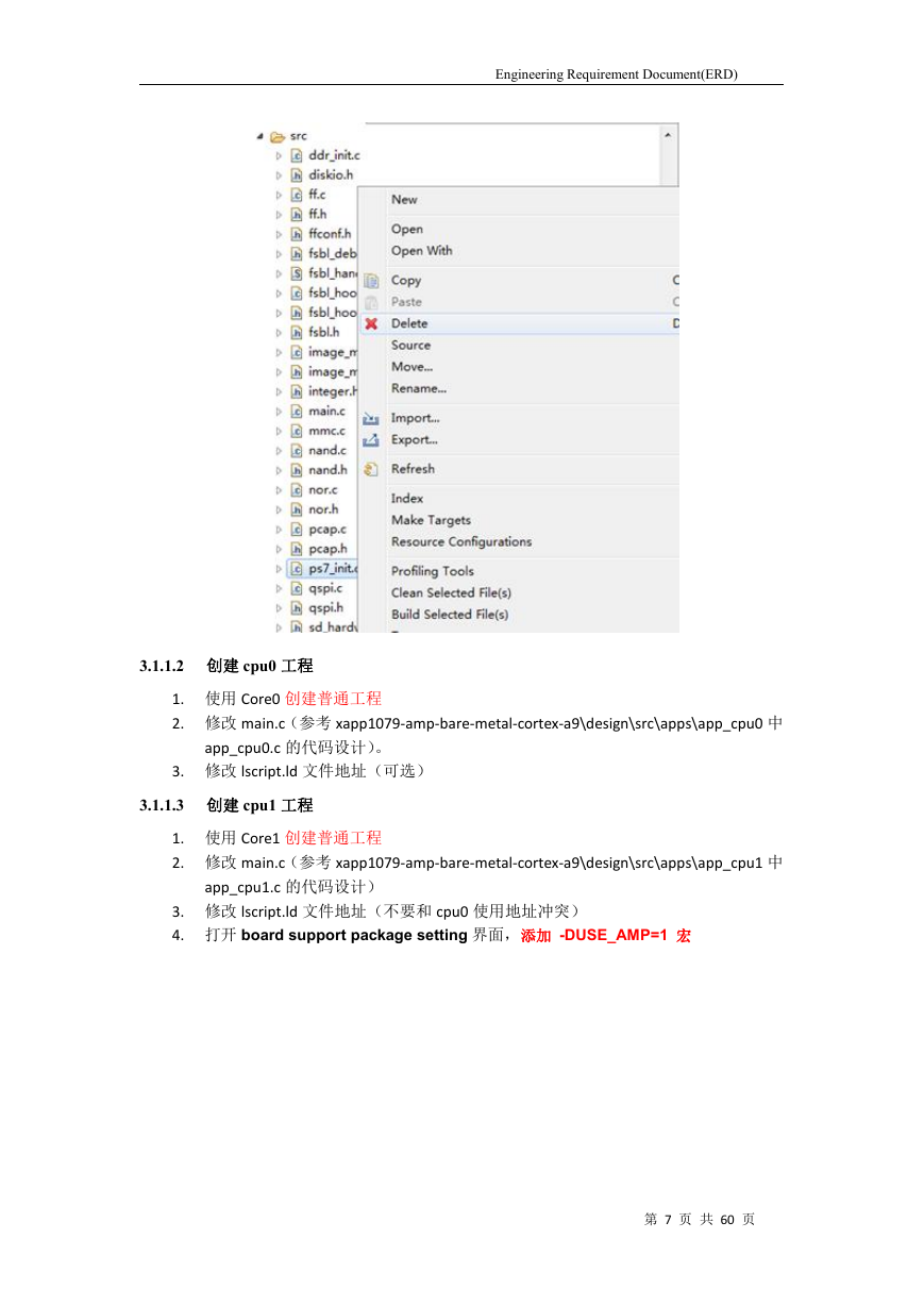
3.1.1.1创建amp_fsbl工程
3.1.1.2创建cpu0工程
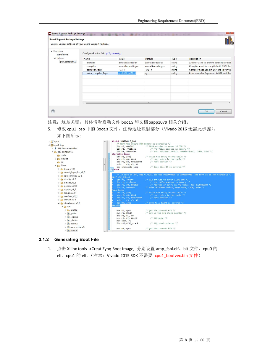
3.1.1.3创建cpu1工程
3.1.2Generating Boot File
3.1.3烧写程序
3.1.4启动
3.1.5调试
3.1.6总结
3.2SMP开发说明
4ZC706启动代码分析
4.1启动代码
4.2Fsbl流程(for AMP)
4.3CPU0启动CPU1流程
5程序在线烧写方案及流程
5.1程序烧写需求
5.2提出该需求的原因
5.3程序烧写方案
5.3.1BOOT.BIN组成
5.3.2BOOT.BIN生成方法
5.4FSBL.bin和APP.bin等的生成
5.5制作*bin及烧写的具体步骤
5.5.1制作*bin流程
5.5.2BOOT.bin制作过程
5.5.3FSBL.bin和APP.bin等的生成过程
5.6烧写BOOT.bin步骤
5.6.1通过SDK工具烧写步骤
5.6.2通过上位机烧写软件的烧写步骤
5.6.3通过串口调试助手烧写步骤
6Zynq Qspi控制器
6.1基本特性
6.2I/O接口
6.3Qspi控制器模式
6.3.1I/O模式
6.3.2线性地址(linear address)模式
6.3.2.1Quad-SPI single SS, 4-bit I/O
6.3.2.2Quad-SPI dual SS, 8-bit parallel I/O
6.3.2.3Quad-SPI dual SS, 4-bit stacked I/O
6.3.3传统(legacy)SPI模式
6.4Qspi 例程
6.5Qspi控制器支持访问32MB方法
6.5.1Bank地址寄存器(Bank address register)
6.5.2扩展地址模式(Extended address mode)
6.5.3使用新写命令(New commands)
6.6QSPI Flash选择
6.7作为BOOT器件考虑
7µC/OS系统启动指南
7.1Introduction
7.1.1Software Requirements
7.1.2Hardware Requirements
7.2Hardware Design
7.2.1Step 1. Invoke the Vivado IDE and Create a project
7.2.2Step 2. Create an IP Integrator Design
7.2.3Step 3. Add and setup the Zynq processor system IP
7.2.4Step 4. Customize the Zynq block for our design
7.2.5Step 5. Add the soft peripherals
7.2.6Step 6. Generate HDL Design Files
7.2.7Step 7. Synthesis, Implement and Generate Bitstrea
7.3Software Design
7.3.1Step 1. Installation of the µC/OS Repository
7.3.2Step 2. Generate the µC/OS BSP
7.3.3Step 3. Build and Debug the Demonstration Project
7.3.4Step 4. Program the AXI Timer 0 with the ucos_axit
7.3.5Step 5. Program the AXI Timer 1 with the Xilinx tm
7.4Conclusion
8Linux系统启动指南



 2023年江西萍乡中考道德与法治真题及答案.doc
 2012年重庆南川中考生物真题及答案.doc
 2013年江西师范大学地理学综合及文艺理论基础考研真题.doc
 2020年四川甘孜小升初语文真题及答案I卷.doc
 2020年注册岩土工程师专业基础考试真题及答案.doc
 2023-2024学年福建省厦门市九年级上学期数学月考试题及答案.doc
 2021-2022学年辽宁省沈阳市大东区九年级上学期语文期末试题及答案.doc
 2022-2023学年北京东城区初三第一学期物理期末试卷及答案.doc
 2018上半年江西教师资格初中地理学科知识与教学能力真题及答案.doc
 2012年河北国家公务员申论考试真题及答案-省级.doc
 2020-2021学年江苏省扬州市江都区邵樊片九年级上学期数学第一次质量检测试题及答案.doc
 2022下半年黑龙江教师资格证中学综合素质真题及答案.doc