Integrated Power Brake –
modular set extension
for highly automated driving
Dipl.-Ing. Urs Bauer
Dipl.-Ing. Mirko Brand
Dr. rer.nat. Thorsten Maucher
Robert Bosch GmbH
© Springer Fachmedien Wiesbaden GmbH 2017
P.E. Pfeffer (Ed.), 8th International Munich Chassis Symposium 2017,
Proceedings, DOI 10.1007/978-3-658-18459-9_48
693
�
Integrated Power Brake (IPB) – modular set extension for highly automated driving
1 Introduction
With the introduction of vehicle stability systems like ESP®, and passive safety systems
like seat belts and airbags, driving safety has been improved and the number of road traf-
fic fatalities and severe injuries have been significantly reduced in the last decades. Alt-
hough these safety systems are state of the art for new passenger cars, in Germany the
number of fatalities remains on a similar level in the latest years. At the same time, the
need of the people for individual mobility is still increasing and this is resulting in higher
traffic density, traffic complexity, and increasing stress for the drivers. Statistical data
shows that the driver remains as an essential source for accidents.
To further increase the driving safety and to relieve the driver of the complex task of
vehicle guidance, today nearly all OEMs and suppliers are dealing with ideas for self-
driving vehicles or are engaged with highly automated driving (HAD) functionalities.
These trends towards new technologies for highly automated driving, the same as
electrification for CO2 reduction and energy efficiency, are resulting in new challeng-
es and requirements for braking and steering architectures.
automated
connected
electrified
It is expected that these highly automated driving functions will be introduced into the
market in the next years. Vehicles shall be able to provide capabilities to drive without
helping hand or guidance by the human driver in at least several use cases.
The variety of these use cases where the vehicle shall operate on its own is currently
very high and often driven by new business models that come up with the newly
available technology.
694
�
Integrated Power Brake (IPB) – modular set extension for highly automated driving
Beyond the area of assisted functions where the driver has at any time the full respon-
sibility for vehicle operation and guidance, some specific use cases are in focus to be
supported by automated driving functions.
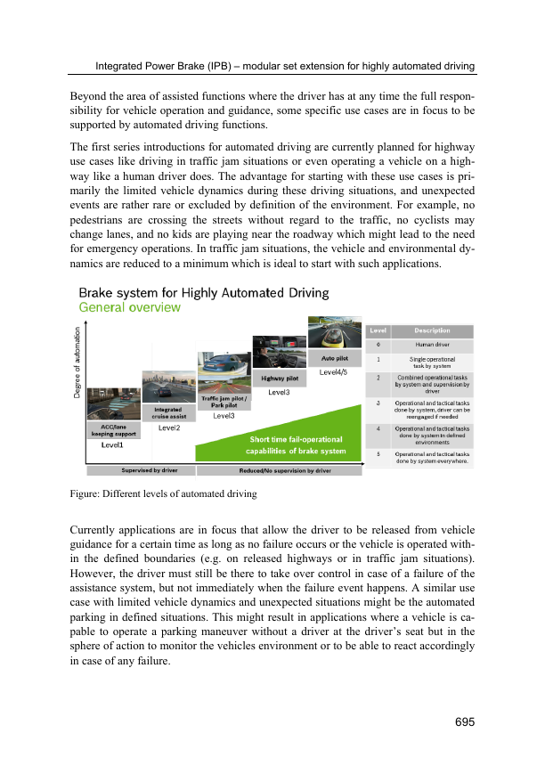
The first series introductions for automated driving are currently planned for highway
use cases like driving in traffic jam situations or even operating a vehicle on a high-
way like a human driver does. The advantage for starting with these use cases is pri-
marily the limited vehicle dynamics during these driving situations, and unexpected
events are rather rare or excluded by definition of the environment. For example, no
pedestrians are crossing the streets without regard to the traffic, no cyclists may
change lanes, and no kids are playing near the roadway which might lead to the need
for emergency operations. In traffic jam situations, the vehicle and environmental dy-
namics are reduced to a minimum which is ideal to start with such applications.
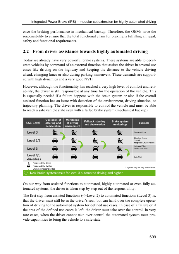
Figure: Different levels of automated driving
Currently applications are in focus that allow the driver to be released from vehicle
guidance for a certain time as long as no failure occurs or the vehicle is operated with-
in the defined boundaries (e.g. on released highways or in traffic jam situations).
However, the driver must still be there to take over control in case of a failure of the
assistance system, but not immediately when the failure event happens. A similar use
case with limited vehicle dynamics and unexpected situations might be the automated
parking in defined situations. This might result in applications where a vehicle is ca-
pable to operate a parking maneuver without a driver at the driver’s seat but in the
sphere of action to monitor the vehicles environment or to be able to react accordingly
in case of any failure.
695
�
Integrated Power Brake (IPB) – modular set extension for highly automated driving
The next evolutional steps, which are already on track, are applications that allow a
car to be operated in urban environments without any human driver in the driver’s
seat. The more difficult situation dynamic, caused by traffic, or unexpected events,
might be covered with higher requirements to the system architecture (e.g. increased
number of sensors).
2 State of the art
2.1 Brake system architectures
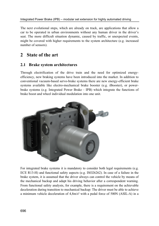
Through electrification of the drive train and the need for optimized energy-
efficiency, new braking systems have been introduced into the market. In addition to
conventional vacuum-based servo-brake systems there are new energy-efficient brake
systems available like electro-mechanical brake booster (e.g. iBooster), or power-
brake systems (e.g. Integrated Power Brake – IPB) which integrate the functions of
brake boost and wheel individual modulation into one unit.
For integrated brake systems it is mandatory to consider both legal requirements (e.g.
ECE R13-H) and functional safety aspects (e.g. ISO26262). In case of a failure in the
brake system, it is assumed that the driver always can control the vehicle by means of
the mechanical backup and adapt his driving behavior after a correspondent warning.
From functional safety analysis, for example, there is a requirement on the achievable
deceleration during transition to mechanical backup: The driver must be able to achieve
a minimum vehicle deceleration of 4,8m/s² with a pedal force of 500N (ASIL-A) in a
696
�
Integrated Power Brake (IPB) – modular set extension for highly automated driving
failed brake-boost situation. This higher deceleration requirement in mechanical back-
up for integrated brake systems, compared to servo-brake systems, results from failure
probabilities for a failed brake-boost situation due to missing redundancy.
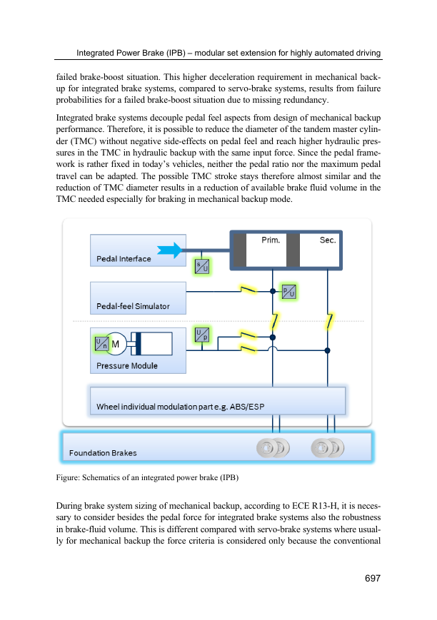
Integrated brake systems decouple pedal feel aspects from design of mechanical backup
performance. Therefore, it is possible to reduce the diameter of the tandem master cylin-
der (TMC) without negative side-effects on pedal feel and reach higher hydraulic pres-
sures in the TMC in hydraulic backup with the same input force. Since the pedal frame-
work is rather fixed in today’s vehicles, neither the pedal ratio nor the maximum pedal
travel can be adapted. The possible TMC stroke stays therefore almost similar and the
reduction of TMC diameter results in a reduction of available brake fluid volume in the
TMC needed especially for braking in mechanical backup mode.
Figure: Schematics of an integrated power brake (IPB)
During brake system sizing of mechanical backup, according to ECE R13-H, it is neces-
sary to consider besides the pedal force for integrated brake systems also the robustness
in brake-fluid volume. This is different compared with servo-brake systems where usual-
ly for mechanical backup the force criteria is considered only because the conventional
697
�
Integrated Power Brake (IPB) – modular set extension for highly automated driving
TMC sizing is oriented on volume consumption requirements for brake fading situations
and provides therefore enough brake fluid volume for the hydraulic backup.
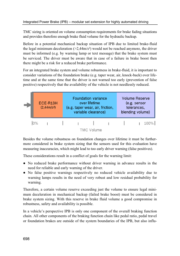
Before in a potential mechanical backup situation of IPB due to limited brake-fluid
the legal minimum deceleration (>2,44m/s²) would not be reached anymore, the driver
must be informed (e.g. by warning lamp or text message) that the brake system must
be serviced. The driver must be aware that in case of a failure in brake boost then
there might be a risk for a reduced brake performance.
For an integrated brake system and volume robustness in brake-fluid, it is important to
consider variations of the foundation brake (e.g. taper wear, air, knock-back) over life-
time and at the same time that the driver is not warned too early (prevention of false
positive) respectively that the availability of the vehicle is not needlessly reduced.
Besides the volume robustness on foundation changes over lifetime it must be further-
more considered in brake system sizing that the sensors used for this evaluation have
measuring inaccuracies, which might lead to too early driver warning (false positives).
These considerations result in a conflict of goals for the warning limit:
● No reduced brake performance without driver warning in advance results in the
need for reliable and early warning of the driver.
● No false positive warnings respectively no reduced vehicle availability due to
warning lamps results in the need of very robust and low residual probability for
warning.
Therefore, a certain volume reserve exceeding just the volume to ensure legal mini-
mum deceleration in mechanical backup (failed brake boost) must be considered in
brake system sizing. With this reserve in brake fluid volume a good compromise in
robustness, safety and availability is possible.
In a vehicle’s perspective IPB is only one component of the overall braking function
chain. All other components of the braking function chain like pedal ratio, pedal travel
or foundation brakes are outside of the system boundaries of the IPB, but also influ-
698
�
Integrated Power Brake (IPB) – modular set extension for highly automated driving
ence the braking performance in mechanical backup. Therefore, the OEMs have the
responsibility to ensure that the total functional chain for braking is fulfilling all legal,
safety and functional requirements.
2.2 From driver assistance towards highly automated driving
Today we already have very powerful brake systems. These systems are able to decel-
erate vehicles by command of an external function that assists the driver in several use
cases like driving on the highway and keeping the distance to the vehicle driving
ahead, changing lanes or also during parking maneuvers. These demands are support-
ed with high dynamics and a very good NVH.
However, although the functionality has reached a very high level of comfort and reli-
ability, the driver is still responsible at any time for the operation of the vehicle. This
is especially needed if a failure happens with the brake system or also if the overall
assisted function has an issue with detection of the environment, driving situation, or
trajectory planning. The driver is responsible to control the vehicle and must be able
to reach a safe vehicle state even with a failed brake system (mechanical backup).
On our way from assisted functions to automated, highly automated or even fully au-
tomated systems, the driver is taken step by step out of the responsibility.
The first step from assisted functions (<=Level 2) to automated functions (Level 3) is,
that the driver must still be in the driver’s seat, but can hand over the complete opera-
tion of driving to the automated system for defined use cases. In case of a failure or if
the area of the defined use cases is left, the driver must take over the control. In very
rare cases, when the driver cannot take over control the automated system must pro-
vide capabilities to bring the vehicle to a safe state.
699
�
Integrated Power Brake (IPB) – modular set extension for highly automated driving
For applications supporting Level 4/5 of automation the driver is no longer mandatory
to be in the driver’s seat and therefore the vehicle has to maintain operation without
support of the driver and bring the vehicle to a safe state.
3 Requirements for highly automated driving
Both, driver assistance functions and highly automated functions result in changed
and new requirements for brake systems and brake system architectures. Oriented on
aircrafts there are higher needs on the availability of the basic function “braking” be-
cause the driver might not take over the task to control the vehicle again after a failure
has occurred.
Current brake systems are designed as “fail safe” devices according to the available
legal requirements (e.g. ECE R13-H). This means, that failures in the brake system
are tolerable as the driver has at any time the responsibility and the capability to take
over the control by means of the brake pedal. That is why today a brake pedal with
mechanical push through is a mandatory design element in power brake systems. Due
to the push through the driver can handle all electrical failures without losing the ca-
pability for modulation of the deceleration.
Moreover, today’s systems might even make use of the driver’s availability, as the
driver might be “part” of the functional designs or might take over some functional
aspects of functional concepts even without detailed knowledge of this (e.g. driver has
to press the brake pedal in order to be able to release the gear latch). Also for mechan-
ical and safety related designs the driver is taken into consideration as it can be as-
sumed that during each braking maneuver the driver might be able to support by ap-
plying the brake pedal.
In fact, the driver is the highly available backup for today’s brake system and his limita-
tions in performance are accepted. To use the driver as backup and design the brake sys-
tem as “fail safe” provides a very high availability and accepts on the other hand that
single failures might lead to a complete loss of wheel individual modulation or brake
boost capability. This approach to use the driver as backup allows at the same time a cer-
tain reduction of monitoring demands as some monitoring duties are transferred to the
driver (e.g. indication of specific noise or feeling during brake pedal apply).
3.1 Brake system requirements derived from state of the art
In general, it is possible to derive the requirements for the backup mode from the ca-
pabilities of a driver operating a brake system. These capabilities, but also restrictions,
are known, accepted, and define the state of the art.
700
�



 2023年江西萍乡中考道德与法治真题及答案.doc
 2012年重庆南川中考生物真题及答案.doc
 2013年江西师范大学地理学综合及文艺理论基础考研真题.doc
 2020年四川甘孜小升初语文真题及答案I卷.doc
 2020年注册岩土工程师专业基础考试真题及答案.doc
 2023-2024学年福建省厦门市九年级上学期数学月考试题及答案.doc
 2021-2022学年辽宁省沈阳市大东区九年级上学期语文期末试题及答案.doc
 2022-2023学年北京东城区初三第一学期物理期末试卷及答案.doc
 2018上半年江西教师资格初中地理学科知识与教学能力真题及答案.doc
 2012年河北国家公务员申论考试真题及答案-省级.doc
 2020-2021学年江苏省扬州市江都区邵樊片九年级上学期数学第一次质量检测试题及答案.doc
 2022下半年黑龙江教师资格证中学综合素质真题及答案.doc