IEEE Std 1386-2001
IEEE Standard for a Common
Mezzanine Card (CMC) Family
Sponsor
Microprocessor & Microcomputer Standards Committee (MMSC)
of the
IEEE Computer Society
Approved 14 June 2001
IEEE-SA Standards Board
Abstract: The mechanics of a common mezzanine card (CMC) family are defined in this standard.
Mezzanine cards, designed to this standard, can be used interchangeably on VME, VME64 and
VME64x boards, CompactPCIfi boards, Multibusfi I and II boards, desktop computers, portable
computers, servers, and other similar types of applications. Mezzanine cards can provide modular
front panel I/O, backplane I/O or general function expansion or a combination for host computers.
Single, wide mezzanine cards are 75 mm wide by 150 mm deep by 8.2 mm high.
Keywords: backplane I/O, bezel, board, card, CompactPCI, face plate, front panel I/O, host com-
puter, I/O, local bus, metric, mezzanine, module, modular I/O, Multibus, PCI, VME, VME64,
VME64x, VMEbus
The Institute of Electrical and Electronics Engineers, Inc.
3 Park Avenue, New York, NY 10016-5997, USA
Copyright ' 2001 by the Institute of Electrical and Electronics Engineers, Inc.
All rights reserved. Published 20 August 2001. Printed in the United States of America.
Print:
PDF:
ISBN 0-7381-2828-7 SH94922
SS94922
ISBN 0-7381-2829-5
No part of this publication may be reproduced in any form, in an electronic retrieval system or otherwise, without the prior
written permission of the publisher.
�
IEEE Standards documents are developed within the IEEE Societies and the Standards Coordinating Committees of the IEEE
Standards Association (IEEE-SA) Standards Board. The IEEE develops its standards through a consensus development pro-
cess, approved by the American National Standards Institute, which brings together volunteers representing varied viewpoints
and interests to achieve the final product. Volunteers are not necessarily members of the Institute and serve without compensa-
tion. While the IEEE administers the process and establishes rules to promote fairness in the consensus development process,
the IEEE does not independently evaluate, test, or verify the accuracy of any of the information contained in its standards.
Use of an IEEE Standard is wholly voluntary. The IEEE disclaims liability for any personal injury, property or other damage, of
any nature whatsoever, whether special, indirect, consequential, or compensatory, directly or indirectly resulting from the pub-
lication, use of, or reliance upon this, or any other IEEE Standard document.
The IEEE does not warrant or represent the accuracy or content of the material contained herein, and expressly disclaims any
express or implied warranty, including any implied warranty of merchantability or fitness for a specific purpose, or that the use
of the material contained herein is free from patent infringement. IEEE Standards documents are supplied AS IS.
The existence of an IEEE Standard does not imply that there are no other ways to produce, test, measure, purchase, market, or
provide other goods and services related to the scope of the IEEE Standard. Furthermore, the viewpoint expressed at the time a
standard is approved and issued is subject to change brought about through developments in the state of the art and comments
received from users of the standard. Every IEEE Standard is subjected to review at least every five years for revision or reaffir-
mation. When a document is more than five years old and has not been reaffirmed, it is reasonable to conclude that its contents,
although still of some value, do not wholly reflect the present state of the art. Users are cautioned to check to determine that
they have the latest edition of any IEEE Standard.
In publishing and making this document available, the IEEE is not suggesting or rendering professional or other services for, or
on behalf of, any person or entity. Nor is the IEEE undertaking to perform any duty owed by any other person or entity to
another. Any person utilizing this, and any other IEEE Standards document, should rely upon the advice of a competent profes-
sional in determining the exercise of reasonable care in any given circumstances.
Interpretations: Occasionally questions may arise regarding the meaning of portions of standards as they relate to specific appli-
cations. When the need for interpretations is brought to the attention of IEEE, the Institute will initiate action to prepare appro-
priate responses. Since IEEE Standards represent a consensus of concerned interests, it is important to ensure that any
interpretation has also received the concurrence of a balance of interests. For this reason, IEEE and the members of its societies
and Standards Coordinating Committees are not able to provide an instant response to interpretation requests except in those
cases where the matter has previously received formal consideration.
Comments for revision of IEEE Standards are welcome from any interested party, regardless of membership affiliation with
IEEE. Suggestions for changes in documents should be in the form of a proposed change of text, together with appropriate sup-
porting comments. Comments on standards and requests for interpretations should be addressed to:
Secretary, IEEE-SA Standards Board
445 Hoes Lane
P.O. Box 1331
Piscataway, NJ 08855-1331
USA
Note: Attention is called to the possibility that implementation of this standard may require use of subject mat-
ter covered by patent rights. By publication of this standard, no position is taken with respect to the existence or
validity of any patent rights in connection therewith. The IEEE shall not be responsible for identifying patents
for which a license may be required by an IEEE standard or for conducting inquiries into the legal validity or
scope of those patents that are brought to its attention.
IEEE is the sole entity that may authorize the use of certification marks, trademarks, or other designations to indicate compli-
ance with the materials set forth herein.
Authorization to photocopy portions of any individual standard for internal or personal use is granted by the Institute of Electri-
cal and Electronics Engineers, Inc., provided that the appropriate fee is paid to Copyright Clearance Center. To arrange for pay-
ment of licensing fee, please contact Copyright Clearance Center, Customer Service, 222 Rosewood Drive, Danvers, MA
01923 USA; +1 978 750 8400. Permission to photocopy portions of any individual standard for educational classroom use can
also be obtained through the Copyright Clearance Center.
�
Introduction
[This introduction is not part of IEEE Std 1386-2001, IEEE Standard for a Common Mezzanine Card (CMC) Family.]
The primary goal of this standard is to provide the mechanics of a mezzanine card family that can be
deployed on a variety of different host computer platforms. These mezzanine cards can be used to provide
front panel I/O, rear panel I/O, additional local host functions, or a combination of all three. The mezzanine
cards local bus can be PCI, SBus, or other local buses as they are developed in the future. The secondary
goal of this standard is to have only one mezzanine card mechanical definition for a specific type of local
bus, instead of multiple mechanical implementations as in the past. Multiple mechanical implementations
fragment the market and destroy economies of scale for manufacturing, engineering, sales, and marketing. A
single mechanical definition builds larger markets with many more unique functions for the multitude of
user applications, and at a lower price. Both the suppliers and users win by enjoying the benefits of a larger
unified market.
SBus Historical: In 1993 when the effort to develop a mezzanine card standard was started, there seemed to
be a market need to shrink the SBus (IEEE 1496) mechanical form factor so that it would fit in a single VME
board slot. (SBus cards are 20.32 mm high and take up a second VME slot when attached to a VME host
board.) A SBus mezzanine card (SMC) draft child standard was developed and reached the sponsor ballot
phase (see Section 1.5 for the definition of child standard). This draft standard, IEEE P1386.2, was titled
Draft Standard Physical and Environmental Layers for SBus: SMC. Due to the overwhelming popularity
of the PCI local bus, no market interest developed for the single slot SBus version, SMC. IEEE P1386.2 was
dropped as a proposed IEEE standard in the summer of 1996.
Futurebusfi Historical: In 1993 most of the core Futurebus+ (IEEE 896.x) standards had been completed.
At that time there seemed to be a reasonable market interest in the Futurebus+ architecture. The mechanics
of placing mezzanine cards on Futurebus+ modules was included in the core IEEE P1386 Draft 2.0 mechan-
ical definition. Unfortunately, the market for Futurebus+ never developed. During this standards sponsor
ballot phase, it was decided to remove all references to Futurebus+ in both the IEEE P1386 and IEEE
P1386.1 draft standards. Since the extended CMC form factor (250 mm deep) version was specified mainly
for the Futurebus+ applications, it was also dropped from both IEEE P1386 and IEEE P1386.1. As a result,
only two CMC form factors are defined: single width and double width.
CompactPCIfi Historical: After the first sponsor ballot in April 1995, a new bus architecture was intro-
duced to the market that rapidly gained large market interest. CompactPCI transformed the PCI local bus
into a backplane bus with a maximum of eight slots. CompactPCI board, backplane, and subrack mechanics
are the same as VME64x, except for the backplane connectors. All the board and subrack mechanics defined
for the VME64x architecture apply directly to CompactPCI. VME64x provides 205 user-defined I/O pins
through the backplane, and CompactPCI provides 315 user-defined I/O pins through the backplane. The PCI
Industrial Computers Manufacturers Group (PICMG) is responsible for the promotion and maintenance of
the CompactPCI specifications.
Routing of PCI mezzanine cards (PMC) I/O to the rear of CompactPCI boards is defined and controlled by
PICMG. Detailed specifications are available on the World Wide Web at the following URL: http://
www.picmg.com.
Special thanks are due to Dave Moore, original Working Group Technical Editor of IEEE Std 1386-2001, for
the generation of the many drafts; to Eike Waltz for the key mechanical designs of the CMC; and to Dave
Rios on the connector design. Heinz Horstmeier, Cliff Lupien, Harry Parkinson, Rick Spratt, and Chau
Pham are also to be thanked for their contribution to the development of this standard.
Copyright ' 2001 IEEE. All rights reserved.
iii
�
Participants
The following is a list of participants in the Working Group for IEEE Std 1386:
Wayne Fischer, Chair and Technical Editor
Malcolm Airst
Harry Andreas
James Barnette
Juergen Baumann
Martin Blake
Hans Brand
Dave Brearley
Gorky Chin
Dick DeBock
Ian Dobson
Mike Hasenfratz
Ryuji Hayasaka
Roger Hinsdale
Heinz Horstmeier
Dave Horton
Anotol Kaganovich
Gary Kidwell
Jing Kowk
Tom Kuleza
Dees Lambreshtse
Sang Dae Lee
Cliff Lupien
Kristian Martinson
Jim Medeiros
Robert McKee
Dave Mendenhall
David Moore
Rob Noffke
Joseph Norris
Harry Parkinson
Elwood Parsons
Chau Pham
Dave Rios
John Rynearson
Richard Spratt
Nobuaki Sugiura
Dennis Terry
Russ Tuck
Jim Turley
Mark Vorenkarmp
Eike Waltz
Dave Wickliff
Bob Widlicka
David Wright
The following members of the balloting committee voted on this standard. Balloters may have voted for approval, disap-
proval, or abstention:
Malcolm Airst
Edmund H. Baulsir
Tom Bertram
Janos Biri
Michael L. Bradley
John L. Cole
Dante Del Corso
Sourav K. Dutta
Roger D. Edwards
Wayne Fischer
Clay E. Hudgins
Lawrence Lamers
Joseph R. Marshall
Klaus-Dieter Mueller
Joseph Norris
Elwood Parsons
Dave A. Perez
Gary S. Robinson
Malcolm Rush
John Rynearson
Thomas J. Schaal
Gary K. Sloane
Hermann H. Strass
Michael G. Thompson
Don Wright
Janusz Zalewski
When the IEEE-SA Standards Board approved this standard on 14 June 2001, it had the following membership:
Donald N. Heirman, Chair
James T. Carlo, Vice Chair
Judith Gorman, Secretary
James H. Gurney
Richard J. Holleman
Lowell G. Johnson
Robert J. Kennelly
Joseph L. Koepfinger*
Peter H. Lips
L. Bruce McClung
Daleep C. Mohla
James W. Moore
Robert F. Munzner
Ronald C. Petersen
Gerald H. Peterson
John B. Posey
Gary S. Robinson
Akio Tojo
Donald W. Zipse
Satish K. Aggarwal
Mark D. Bowman
Gary R. Engmann
Harold E. Epstein
H. Landis Floyd
Jay Forster*
Howard M. Frazier
Ruben D. Garzon
*Member Emeritus
Also included is the following nonvoting IEEE-SA Standards Board liaison:
Alan Cookson, NIST Representative
Donald R. Volzka, TAB Representative
Andrew D. Ickowicz
IEEE Standards Project Editor
CompactPCIfi and PICMGfi are registered trademarks of the PCI Industrial Computers Manufacturers Group.
Multibusfi is a registered trademark of Intel Corporation.
iv
Copyright ' 2001 IEEE. All rights reserved.
�
Contents
1.
Overview.............................................................................................................................................. 1
1.1 Scope............................................................................................................................................ 1
1.2 Purpose......................................................................................................................................... 1
1.3 General arrangement.................................................................................................................... 1
1.4 Theory and operation of usage..................................................................................................... 2
1.5 Parent-child standard ................................................................................................................... 4
1.6 Conformance................................................................................................................................ 4
1.7 Dimensions .................................................................................................................................. 5
1.8 Coordinate dimensions ................................................................................................................ 5
2.
References............................................................................................................................................ 5
2.1 Trademarks .................................................................................................................................. 6
2.2 Relationship between VME, VMEbus, VME64, VME64x, and CompactPCI ........................... 7
3.
Definitions, abbreviations, and terminology........................................................................................ 7
3.1 Special word usage ...................................................................................................................... 7
3.2 Definitions ................................................................................................................................... 7
3.3 Abbreviations............................................................................................................................... 8
3.4 Dimensional nomenclature height, width, and depth .................................................................. 8
4. Mezzanine card mechanics .................................................................................................................. 8
4.1 CMC size designations and sizes................................................................................................. 8
4.2 EMC envelope ............................................................................................................................. 9
4.3 CMC dimensions ......................................................................................................................... 9
4.4 Voltage keying........................................................................................................................... 10
4.5 Connector pads and labeling...................................................................................................... 10
4.6 CMC connector.......................................................................................................................... 11
4.7 CMC connector assembled on a CMC ...................................................................................... 11
4.8 CMC component heights ........................................................................................................... 12
4.9 CMC connector and standoff heights ........................................................................................ 14
4.10 CMC bezel ................................................................................................................................. 15
4.11 CMC test dimensions................................................................................................................. 15
4.12 I/O capability ............................................................................................................................. 15
4.13 Power consumption and dissipation .......................................................................................... 16
4.14 Ground connections ................................................................................................................... 18
4.15 Electromagnetic compatibility................................................................................................... 18
4.16 Shock and vibration ................................................................................................................... 18
4.17 Environmental............................................................................................................................ 18
4.18 MTBF......................................................................................................................................... 19
4.19 ESD design ................................................................................................................................ 19
4.20 ESD kit....................................................................................................................................... 19
5.
Host CMC slot mechanics ................................................................................................................. 19
5.1 Stacking height above the host PCB.......................................................................................... 20
5.2 Host PCB mechanics ................................................................................................................. 20
5.3 Connector pads and labeling...................................................................................................... 22
Copyright ' 2001 IEEE. All rights reserved.
v
�
5.4 CMC connectors ........................................................................................................................ 22
5.5 CMC connector assembled on a host......................................................................................... 24
5.6 Host board side 1 component height.......................................................................................... 25
5.7 Extra shoulder for 13 mm hosts................................................................................................. 26
5.8 Voltage keying pins ................................................................................................................... 27
5.9 Host front panel or host face plate opening ............................................................................... 27
5.10 Filler panels................................................................................................................................ 27
5.11 Host test dimensions .................................................................................................................. 30
5.12 I/O capability ............................................................................................................................. 32
5.13 Power dissipation....................................................................................................................... 32
5.14 Grounding connections.............................................................................................................. 32
5.15 Electromagnetic compatibility................................................................................................... 32
5.16 Environmental............................................................................................................................ 33
6.
Electrical and logical layers............................................................................................................... 33
6.1 Connector utilization.................................................................................................................. 33
6.2 CMC connector pin assignments ............................................................................................... 33
6.3 Rear I/O mapping....................................................................................................................... 33
6.4 BUSMODE signals.................................................................................................................... 35
vi
Copyright ' 2001 IEEE. All rights reserved.
�
IEEE Standard for a Common
Mezzanine Card (CMC) Family
1. Overview
1.1 Scope
This standard defines the mechanics for a common set of slim mezzanine cards that can be used on VME,
VME64 and VME64x boards, CompactPCIfi boards, Multibusfi I and II boards; desktop computers; porta-
ble computers; servers; and other similar computer applications. Mezzanine cards based on this standard can
be used to provide modular front panel I/O, backplane I/O, or general function expansion for the host com-
puter.
1.2 Purpose
The majority of the popular reduced instruction set computer (RISC) and complex instruction set computer
(CISC) microprocessors use the same logical and electrical layer for their high-speed local bus. These same
processors are being incorporated onto VME64x boards, CompactPCI boards, Multibus I and II boards,
desktop computers, portable computers, servers, and other types of computer systems. There is a large mar-
ket need for modular I/O and modular local function expansion via slim mezzanine cards mounted parallel
above the host computers board.
This standard defines the mezzanine card mechanics for these types of applications. This mechanical defini-
tion is based on IEEE Std 1301.4-1996.1
1.3 General arrangement
Mezzanine cards are intended to be used where slim parallel-card mounting is required as in embedded sin-
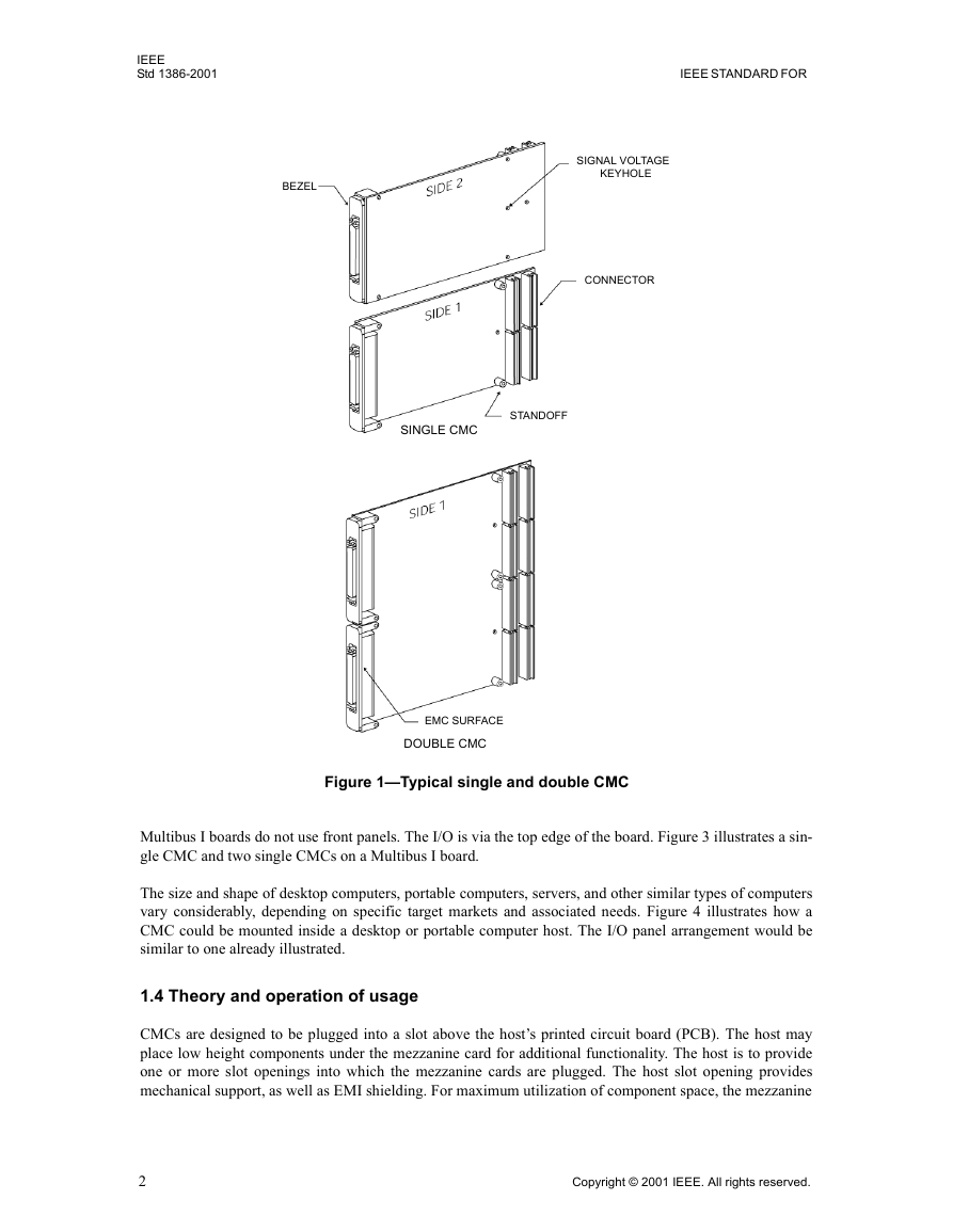
gle-board computers, desktop computers, portable computers, and servers. Figure 1 illustrates a single-size
and a double-size mezzanine card defined by this standard.
Typical single- and double-size common mezzanine cards (CMCs) on VME64x boards are illustrated in
Figure 2. Implementation of CMCs on CompactPCI and Multibus II boards is similar to that of 6U VME64x
boards except that Multibus II boards are 220 mm deep and CompactPCI boards use a 2 mm connector sys-
tem. CMCs can also be used on 3U VME64x and CompactPCI boards.
1Information on references can be found in Clause 2.
Copyright ' 2001 IEEE. All rights reserved.
1
�
IEEE
Std 1386-2001
IEEE STANDARD FOR
BEZEL
SIGNAL VOLTAGE
KEYHOLE
CONNECTOR
SINGLE CMC
STANDOFF
EMC SURFACE
DOUBLE CMC
Figure 1Typical single and double CMC
Multibus I boards do not use front panels. The I/O is via the top edge of the board. Figure 3 illustrates a sin-
gle CMC and two single CMCs on a Multibus I board.
The size and shape of desktop computers, portable computers, servers, and other similar types of computers
vary considerably, depending on specific target markets and associated needs. Figure 4 illustrates how a
CMC could be mounted inside a desktop or portable computer host. The I/O panel arrangement would be
similar to one already illustrated.
1.4 Theory and operation of usage
CMCs are designed to be plugged into a slot above the hosts printed circuit board (PCB). The host may
place low height components under the mezzanine card for additional functionality. The host is to provide
one or more slot openings into which the mezzanine cards are plugged. The host slot opening provides
mechanical support, as well as EMI shielding. For maximum utilization of component space, the mezzanine
2
Copyright ' 2001 IEEE. All rights reserved.
�


 2023年江西萍乡中考道德与法治真题及答案.doc
 2012年重庆南川中考生物真题及答案.doc
 2013年江西师范大学地理学综合及文艺理论基础考研真题.doc
 2020年四川甘孜小升初语文真题及答案I卷.doc
 2020年注册岩土工程师专业基础考试真题及答案.doc
 2023-2024学年福建省厦门市九年级上学期数学月考试题及答案.doc
 2021-2022学年辽宁省沈阳市大东区九年级上学期语文期末试题及答案.doc
 2022-2023学年北京东城区初三第一学期物理期末试卷及答案.doc
 2018上半年江西教师资格初中地理学科知识与教学能力真题及答案.doc
 2012年河北国家公务员申论考试真题及答案-省级.doc
 2020-2021学年江苏省扬州市江都区邵樊片九年级上学期数学第一次质量检测试题及答案.doc
 2022下半年黑龙江教师资格证中学综合素质真题及答案.doc