SURFACE
VEHICLE
STANDARD
J1979
REV.
APR2002
Issued
Revised
1991-12
2002-04
Superseding J1979 SEP1997
(R) E/E Diagnostic Test Modes —
Equivalent to ISO/DIS 15031-5:April 30, 2002
This document supersedes SAE J1979 SEP1997, and is technically equivalent to ISO/DIS 15031-5:April 30, 2002,
except for minor reorganisation of Paragraphs 1 and 2.
Foreword—On-Board Diagnostic (OBD) regulations require passenger cars, and light and medium duty trucks, to
support communication of a minimum set of diagnostic information to off-board “generic” test equipment. This
document specifies diagnostic services and functionally addressed request / response messages required to be
supported by motor vehicles and external test equipment for diagnostic purposes which pertain to motor vehicle
emission-related data. These messages are intended to be used by any external test equipment meeting the
requirements of SAE J1978 for retrieval of OBD information from a vehicle.
SAE J1979 was originally developed to meet U.S. OBD requirements for 1996 and later model year vehicles. ISO
15031-5 was based on SAE J1979 and was intended to combine the U.S. requirements with European OBD
requirements for 2000 and later model year vehicles. In addition, this document and later versions of the ISO/DIS
document include new data reporting requirements included in proposed U.S. regulations, and also include
specific requirements for retrieval of the same diagnostic information from vehicles equipped with ISO 15765-4 as
a diagnostic data link.
SAE Technical Standards Board Rules provide that: “This report is published by SAE to advance the state of technical and engineering sciences. The use of this report is entirely
voluntary, and its applicability and suitability for any particular use, including any patent infringement arising therefrom, is the sole responsibility of the user.”
SAE reviews each technical report at least every five years at which time it may be reaffirmed, revised, or cancelled. SAE invites your written comments and suggestions.
Copyright ©2002 Society of Automotive Engineers, Inc.
All rights reserved. No part of this publication may be reproduced, stored in a retrieval system or transmitted, in any form or by any means, electronic, mechanical, photocopying,
recording, or otherwise, without the prior written permission of SAE.
TO PLACE A DOCUMENT ORDER:
SAE WEB ADDRESS:
Tel:
Tel:
Fax:
Email:
http://www.sae.org
877-606-7323 (inside USA and Canada)
724-776-4970 (outside USA)
724-776-0790
custsvc@sae.org
�
SAE J1979 Revised APR2002
TABLE OF CONTENTS
1
1.1
1.2
2
2.1
2.1.1
2.1.2
2.2
2.2.1
2.2.2
3
4
4.1
4.1.1
4.1.2
4.1.3
4.1.4
4.1.5
4.2
4.2.1
4.2.2
4.2.3
4.2.4
4.2.5
4.2.6
4.2.7
4.2.8
4.2.9
4.2.10
4.3
4.4
4.5
5
5.1
5.1.1
5.1.2
5.1.3
5.1.4
5.2
5.2.1
5.2.2
5.2.3
5.2.4
5.3
5.3.1
5.3.2
5.3.3
5.3.4
Scope........................................................................................................................................................4
Purpose ....................................................................................................................................................4
Differences from ISO Document...............................................................................................................5
Reference(s) .............................................................................................................................................6
Applicable Publications .............................................................................................................................6
SAE Publications ......................................................................................................................................6
ISO Publications .......................................................................................................................................6
Related Publications .................................................................................................................................6
SAE Publications ......................................................................................................................................6
ISO Documents ........................................................................................................................................6
Term(s) and Definition(s) ..........................................................................................................................6
Technical Requirements ...........................................................................................................................8
Diagnostic Service, General Requirements..............................................................................................8
Multiple Responses to a Single Data Request .........................................................................................8
Application Timing Parameter Definition ...................................................................................................8
Minimum Time between Requests from External Test Equipment ......................................................... 10
Data Not Available ..................................................................................................................................15
Maximum Value ...................................................................................................................................... 19
Diagnostic Message Format ................................................................................................................... 19
Addressing Method ................................................................................................................................. 19
Maximum Message Length .....................................................................................................................19
Request/Response Message Format ..................................................................................................... 20
Response Code Parameter Definition ....................................................................................................21
Header Byte Definition of ISO 9141-2, ISO 14230-4, and SAE J1850 ................................................... 22
Header Byte Definition of ISO 15765-4 .................................................................................................. 22
Data Bytes Definition of ISO 9141-2, ISO 14230-4, SAE J1850, and ISO 15765-4 ............................... 23
Non-Data Bytes included in Diagnostic Messages with SAE J1850....................................................... 23
Non-Data Bytes included in Diagnostic Messages with ISO 9141-2 and ISO 14230-4.......................... 23
Bit Position Convention........................................................................................................................... 23
Allowance for Expansion and Enhanced Diagnostic Services ................................................................ 23
Definition of PIDs for Service $01 and $02 .............................................................................................23
Format of Data to be Displayed ..............................................................................................................23
Diagnostic Service Definition for ISO 9141-2, ISO 14230-4, and SAE J1850 ........................................ 24
Service $01 - Request Current Powertrain Diagnostic Data ................................................................... 24
Functional Description ............................................................................................................................24
Message Data Bytes ...............................................................................................................................25
Parameter Definition ...............................................................................................................................26
Message Example ..................................................................................................................................26
Service $02 - Request Powertrain Freeze Frame Data.......................................................................... 29
Functional description ............................................................................................................................. 29
Message Data Bytes ...............................................................................................................................30
Parameter Definition ...............................................................................................................................31
Message Example ..................................................................................................................................31
Service $03 - Request Emission-Related Diagnostic Trouble Codes ..................................................... 32
Functional Description ............................................................................................................................32
Message Data Bytes ...............................................................................................................................33
Parameter Definition ...............................................................................................................................34
Message Example ..................................................................................................................................34
-2-
�
5.4
5.4.1
5.4.2
5.4.3
5.4.4
5.5
5.5.1
5.5.2
5.5.3
5.5.4
5.6
5.6.1
5.6.2
5.6.3
5.6.4
5.7
5.7.1
5.7.2
5.7.3
5.7.4
5.8
5.8.1
5.8.2
5.8.3
5.8.4
5.9
5.9.1
5.9.2
5.9.3
5.9.4
6.
6.1
6.1.1
6.1.2
6.1.3
6.1.4
6.2
6.2.1
6.2.2
6.2.3
6.2.4
6.3
6.3.1
6.3.2
6.3.3
6.3.4
6.4
6.4.1
6.4.2
6.4.3
6.4.4
6.5
SAE J1979 Revised APR2002
Service $04 - Clear/Reset Emission-Related Diagnostic Information ..................................................... 37
Functional Description ............................................................................................................................37
Message Data Bytes ...............................................................................................................................37
Parameter Definition ...............................................................................................................................37
Message Example ..................................................................................................................................37
Service $05 - Request Oxygen Sensor Monitoring Test Results............................................................ 39
Functional Description ............................................................................................................................39
Message Data Bytes ...............................................................................................................................39
Parameter Definition ...............................................................................................................................40
Message Example ..................................................................................................................................41
Service $06 - Request On-Board Monitoring Test Results for Specific Monitored Systems .................. 43
Functional Description ............................................................................................................................43
Message Data Bytes ...............................................................................................................................43
Parameter Definition ...............................................................................................................................44
Message Example ..................................................................................................................................45
Service $07 - Request Emission-Related Diagnostic Trouble Codes Detected
During Current or Last Completed Driving Cycle .................................................................................... 47
Functional Description ............................................................................................................................47
Message Data Bytes ...............................................................................................................................47
Parameter Definition ...............................................................................................................................48
Message Example ..................................................................................................................................48
Service $08 - Request Control of On-Board System, Test or Component ............................................. 48
Functional Description ............................................................................................................................48
Message Data Bytes ...............................................................................................................................48
Parameter Definition ...............................................................................................................................50
Message Example ..................................................................................................................................50
Service $09 - Request Vehicle Information ............................................................................................ 51
Functional Description ............................................................................................................................51
Message Data Bytes ...............................................................................................................................51
Parameter Definition ...............................................................................................................................52
Message Example ..................................................................................................................................53
Diagnostic Service Definition for ISO 15765-4 ....................................................................................... 63
Service $01 - Request Current Powertrain Diagnostic Data ................................................................... 63
Functional Description ............................................................................................................................63
Message Data Bytes ...............................................................................................................................63
Parameter Definition ...............................................................................................................................65
Message Example ..................................................................................................................................65
Service $02 - Request Powertrain Freeze Frame Data.......................................................................... 69
Functional Description ............................................................................................................................69
Message Data Bytes ...............................................................................................................................69
Parameter Definition ...............................................................................................................................71
Message Example ..................................................................................................................................71
Service $03 - Request Emission-Related Diagnostic Trouble Codes ..................................................... 74
Functional Description ............................................................................................................................74
Message Data Bytes ...............................................................................................................................74
Parameter Definition ...............................................................................................................................75
Message Example ..................................................................................................................................75
Service $04 - Clear/Reset Emission-Related Diagnostic Information ..................................................... 76
Functional Description ............................................................................................................................76
Message Data Bytes ...............................................................................................................................76
Parameter Definition ...............................................................................................................................77
Message Example ..................................................................................................................................77
Service $05 - Request Oxygen Sensor Monitoring Test Results............................................................ 78
-3-
�
SAE J1979 Revised APR2002
6.6
6.6.1
6.6.2
6.6.3
6.6.4
6.7
6.7.1
6.7.2
6.7.3
6.7.4
6.8
6.8.1
6.8.2
6.8.3
6.8.4
6.9
6.9.1
6.9.2
6.9.3
6.9.4
7.
7.1
Service $06 - Request On-Board Monitoring Test Results for Specific Monitored Systems .................. 78
Functional Description ............................................................................................................................78
Message Data Bytes ...............................................................................................................................78
Parameter Definition ...............................................................................................................................80
Message Example ..................................................................................................................................83
Service $07 - Request Emission-Related Diagnostic Trouble Codes Detected
During Current or Last Completed Driving Cycle .................................................................................... 85
Functional Description ............................................................................................................................85
Message Data Bytes ...............................................................................................................................86
Parameter Definition ...............................................................................................................................86
Message Example ..................................................................................................................................86
Service $08 - Request Control of On-Board System, Test or Component ............................................. 86
Functional Description ............................................................................................................................86
Message Data Bytes ...............................................................................................................................87
Parameter Definition ...............................................................................................................................88
Message Example ..................................................................................................................................88
Service $09 - Request Vehicle Information ............................................................................................ 90
Functional Description ............................................................................................................................90
Message Data Bytes ...............................................................................................................................90
Parameter Definition ...............................................................................................................................92
Message Example ..................................................................................................................................92
Notes ......................................................................................................................................................98
Marginal Indicia....................................................................................................................................... 98
Appendix A (normative) PID (Parameter ID)/OBDMID (On-Board Monitor ID) /
TID (Test ID)/INFOTYPE supported definition........................................................................................ 99
Appendix B (normative) PIDs (Parameter ID) for Service $01 and $02 Scaling and Definition ...............................100
Appendix C (normative) TIDs (Test ID) for Service $05 Scaling and Definition .......................................................122
Appendix D (normative) OBDMIDs (On-Board Diagnostic Monitor ID) Definition for Service $06 ...........................123
Appendix E (normative) Unit and Scaling ID definition for service $06....................................................................127
Unsigned Unit and Scaling Identifiers Definition ...................................................................................127
E.1
E.2
Signed Unit and Scaling Identifiers Definition .......................................................................................144
Appendix F (normative) TIDs (Test ID) for Service $08 Scaling and Definition .......................................................152
Appendix G (normative) INFOTYPEs for Service $09 Scaling and Definition..........................................................153
1.
Scope
1.1 Purpose—This document supersedes SAE J1979 SEP1997, and is technically equivalent to ISO/DIS 15031-
5:April 30, 2002.
This SAE Recommended Practice is intended to satisfy the data reporting requirements of On-Board
Diagnostic (OBD) regulations in the United States and Europe, and any other region that may adopt similar
requirements in the future. This document specifies:
a. Message formats for request and response messages,
b. Timing requirements between request messages from external test equipment and response
messages from vehicles, and between those messages and subsequent request messages,
c. Behavior of both the vehicle and external test equipment if data is not available,
d. A set of diagnostic services, with corresponding content of request and response messages, to satisfy
OBD regulations,
-4-
�
SAE J1979 Revised APR2002
This document includes capabilities required to satisfy OBD requirements for multiple regions, model years,
engine types, and vehicle types. Those regulations are not yet final for some regions, and are expected to
change in the future. This document makes no attempt to interpret the regulations and does not include
applicability of the included diagnostic services and data parameters for various vehicle applications. The user
of this document is responsible to verify the applicability of each section of this document for a specific vehicle,
engine, model year and region.
This document is based on the Open Systems Interconnection (OSI) Basic Reference Model in accordance
with ISO/IEC 7498 and ISO/IEC 10731 which structures communication systems into seven layers as shown in
the table below.
TABLE 1—APPLICABILITY AND RELATIONSHIP BETWEEN DOCUMENTS
Applicability
OSI 7 layer
Emissions-related
Applicability
OSI 7 layer
Emissions-related
diagnostics
Physical (layer 1)
ISO 9141-2
ISO 14230-1
SAE J1850
Seven layer
according to
Data link (layer 2)
ISO 9141-2
ISO 14230-2
SAE J1850
ISO/IEC 7498
Network (layer 3)
and
ISO/IEC 10731
Transport (layer 4)
Session (layer 5)
Presentation (layer 6)
Application (layer 7)
---
---
---
---
---
---
---
---
---
---
---
---
diagnostics
ISO 11898,
ISO 15765-4
ISO 11898,
ISO 15765-4
ISO 15765-2,
ISO 15765-4
---
ISO 15765-4
---
SAE J1979 /
ISO 15031-5
SAE J1979 /
ISO 15031-5
SAE J1979 /
ISO 15031-5
SAE J1979 /
ISO 15031-5
1.2 Differences from ISO Document—There are no technical differences between this document and ISO/DIS
15031-5:April 30, 2002.
NOTE— Both this document and the ISO 15031-5 document are intended to satisfy the requirements of OBD
requirements in the United States and Europe, and any other region that may adopt similar
requirements in the future. Those regulations change with time, and often when a requirement is
introduced in one region, it will later also become a requirement in another region. The ISO task
force responsible for ISO 15031-5 and the SAE task force work closely together to maintain
consistency in diagnostic reporting requirements in these two documents, and to ensure usability of
these documents for all regions. The goal is to maintain identical technical content in the two
documents, but this document may need to change if additional capabilities are required for the U.S.
before the ISO document can be modified to include those changes.
-5-
�
2.
References
SAE J1979 Revised APR2002
2.1 Applicable Publications—The following publications form a part of this specification to the extent specified
herein. Unless otherwise indicated, the latest version of SAE publications shall apply.
2.1.1
SAE PUBLICATIO NS—Available from SAE, 400 Commonwealth Drive, Warrendale, PA 15096-0001.
SAE J1850: MAY2001—Class B Data Communications Network Interface.
SAE J1930—Electrical/Electronic Systems Diagnostic Terms, Definitions, Abbreviations, and Acronyms -
Equivalent to ISO/TR 15031-2: April 30, 2002
SAE J1978—OBD II Scan Tool - Equivalent to ISO/DIS 15031-4:December 14, 2001
SAE J2012—Diagnostic Trouble Code Definitions - Equivalent to ISO/DIS 15031-6:April 30, 2002
2.1.2
ISO DO CUMENTS—Available from ANSI, 25 West 43rd Street, New York, NY 10036-8002.
ISO 9141-2: 1994—Road vehicles - Diagnostic systems - Part 2: CARB requirements for interchange of
digital information
ISO 9141-2: 1994/ Amd.1:1996—Road vehicles - Diagnostic systems - Part 2: CARB requirements for
interchange of digital information Amendment 1
ISO 14230-4:2000—Road vehicles - Keyword protocol 2000 for diagnostic systems - Part 4: Requirements
for emissions-related systems
ISO/DIS 15031-5: April 30, 2002—Road vehicles - Communication between vehicle and external test
equipment for emissions-related diagnostics - Part 5: Emissions related diagnostic services
ISO 15765-2—Road vehicles – Diagnostics on Controller Area Network (CAN) – Part 2: Network layer
services
ISO 15765-4—Road vehicles – Diagnostics on Controller Area Network (CAN) – Part 4: Requirements for
emissions-related systems
2.2 Related Publications—The following publications are provided for information purposes only and are not a
required part of this specification.
2.2.1
SAE PUBLICATIO N—Available from SAE, 400 Commonwealth Drive, Warrendale, PA 15096-0001.
SAE J1962—Diagnostic Connector - Equivalent to ISO/DIS 15031-3:December 14, 2001
2.2.2
ISO DO CUMENT—Available from ANSI, 25 West 43rd Street, New York, NY 10036-8002.
ISO 15031-1:2001—Road vehicles - Communication between vehicle and external test equipment for
emissions-related diagnostics - Part 1: General information
3.
Term(s) and Definition(s)
3.1 Absolute Throttle Position Sensor—This value is intended to represent the throttle opening.
NOTE— For systems where the output is proportional to the input voltage, this value is the percent of
maximum input signal. For systems where the output is inversely proportional to the input voltage,
this value is 100% minus the percent of maximum input signal. Throttle position at idle will usually
indicate greater than 0%, and throttle position at wide open throttle will usually indicate less than
100%.
-6-
�
SAE J1979 Revised APR2002
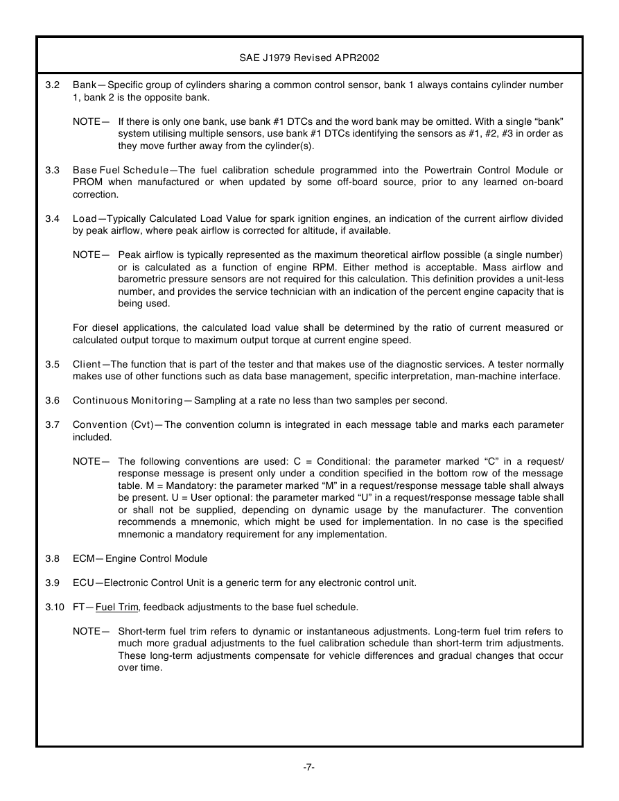
3.2 Bank—Specific group of cylinders sharing a common control sensor, bank 1 always contains cylinder number
1, bank 2 is the opposite bank.
NOTE— If there is only one bank, use bank #1 DTCs and the word bank may be omitted. With a single “bank”
system utilising multiple sensors, use bank #1 DTCs identifying the sensors as #1, #2, #3 in order as
they move further away from the cylinder(s).
3.3 Base Fuel Schedule—The fuel calibration schedule programmed into the Powertrain Control Module or
PROM when manufactured or when updated by some off-board source, prior to any learned on-board
correction.
3.4
Load—Typically Calculated Load Value for spark ignition engines, an indication of the current airflow divided
by peak airflow, where peak airflow is corrected for altitude, if available.
NOTE— Peak airflow is typically represented as the maximum theoretical airflow possible (a single number)
or is calculated as a function of engine RPM. Either method is acceptable. Mass airflow and
barometric pressure sensors are not required for this calculation. This definition provides a unit-less
number, and provides the service technician with an indication of the percent engine capacity that is
being used.
For diesel applications, the calculated load value shall be determined by the ratio of current measured or
calculated output torque to maximum output torque at current engine speed.
3.5 Client—The function that is part of the tester and that makes use of the diagnostic services. A tester normally
makes use of other functions such as data base management, specific interpretation, man-machine interface.
3.6 Continuous Monitoring—Sampling at a rate no less than two samples per second.
3.7 Convention (Cvt)—The convention column is integrated in each message table and marks each parameter
included.
NOTE— The following conventions are used: C = Conditional: the parameter marked “C” in a request/
response message is present only under a condition specified in the bottom row of the message
table. M = Mandatory: the parameter marked “M” in a request/response message table shall always
be present. U = User optional: the parameter marked “U” in a request/response message table shall
or shall not be supplied, depending on dynamic usage by the manufacturer. The convention
recommends a mnemonic, which might be used for implementation. In no case is the specified
mnemonic a mandatory requirement for any implementation.
3.8 ECM—Engine Control Module
3.9 ECU—Electronic Control Unit is a generic term for any electronic control unit.
3.10 FT—Fuel Trim, feedback adjustments to the base fuel schedule.
NOTE— Short-term fuel trim refers to dynamic or instantaneous adjustments. Long-term fuel trim refers to
much more gradual adjustments to the fuel calibration schedule than short-term trim adjustments.
These long-term adjustments compensate for vehicle differences and gradual changes that occur
over time.
-7-
�
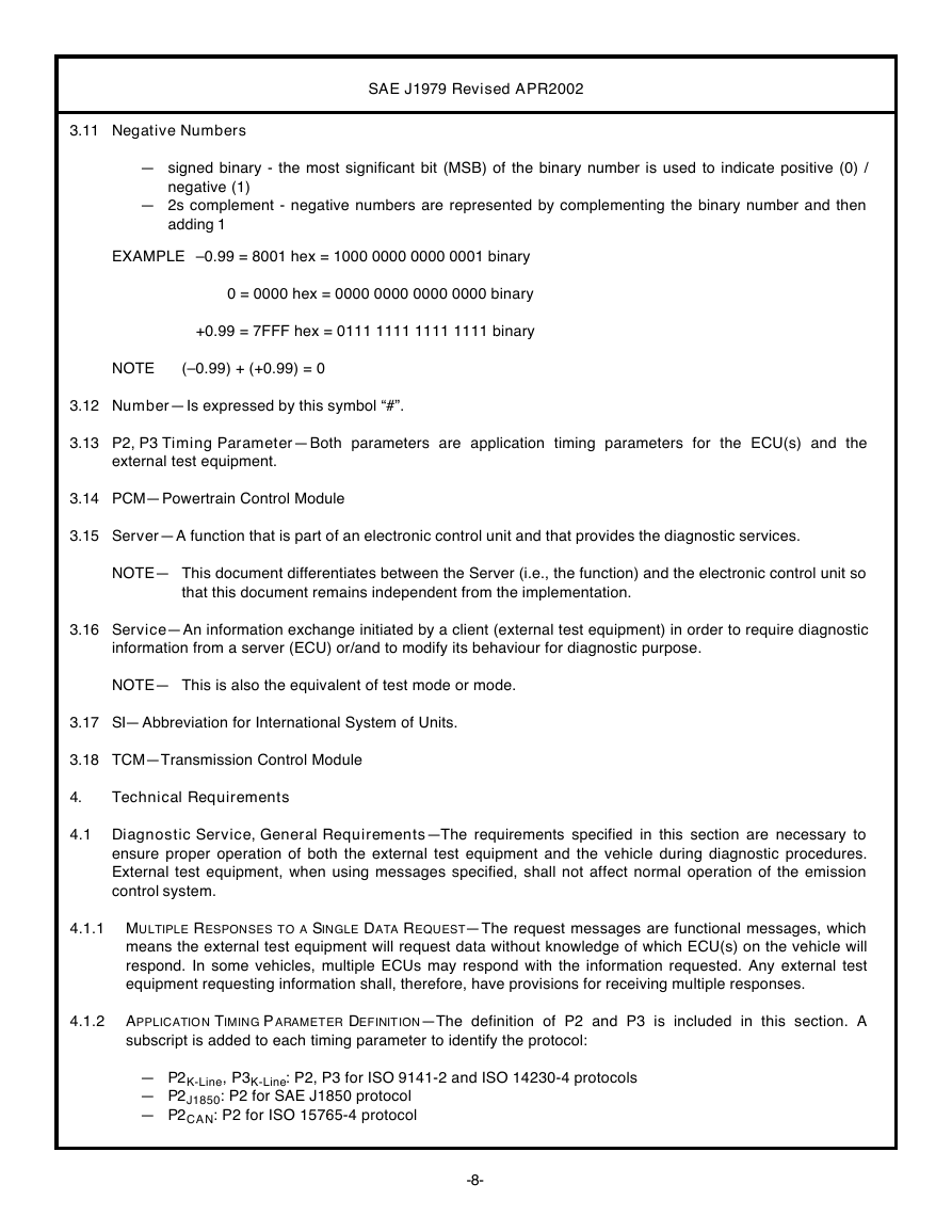
3.11 Negative Numbers
SAE J1979 Revised APR2002
— signed binary - the most significant bit (MSB) of the binary number is used to indicate positive (0) /
negative (1)
— 2s complement - negative numbers are represented by complementing the binary number and then
adding 1
EXAMPLE –0.99 = 8001 hex = 1000 0000 0000 0001 binary
0 = 0000 hex = 0000 0000 0000 0000 binary
+0.99 = 7FFF hex = 0111 1111 1111 1111 binary
NOTE
(–0.99) + (+0.99) = 0
3.12 Number—Is expressed by this symbol “#”.
3.13 P2, P3 Timing Parameter—Both parameters are application timing parameters for the ECU(s) and the
external test equipment.
3.14 PCM—Powertrain Control Module
3.15 Server—A function that is part of an electronic control unit and that provides the diagnostic services.
NOTE— This document differentiates between the Server (i.e., the function) and the electronic control unit so
that this document remains independent from the implementation.
3.16 Service—An information exchange initiated by a client (external test equipment) in order to require diagnostic
information from a server (ECU) or/and to modify its behaviour for diagnostic purpose.
NOTE— This is also the equivalent of test mode or mode.
3.17 SI— Abbreviation for International System of Units.
3.18 TCM—Transmission Control Module
4.
Technical Requirements
4.1 Diagnostic Service, General Requirements—The requirements specified in this section are necessary to
ensure proper operation of both the external test equipment and the vehicle during diagnostic procedures.
External test equipment, when using messages specified, shall not affect normal operation of the emission
control system.
4.1.1 MULTIPLE RESPONSES TO A SINGLE DATA REQUEST—The request messages are functional messages, which
means the external test equipment will request data without knowledge of which ECU(s) on the vehicle will
respond. In some vehicles, multiple ECUs may respond with the information requested. Any external test
equipment requesting information shall, therefore, have provisions for receiving multiple responses.
4.1.2
APPLICATIO N TIMING P ARAMETER DEFINITION—The definition of P2 and P3 is included in this section. A
subscript is added to each timing parameter to identify the protocol:
— P2K-Line, P3K-Line: P2, P3 for ISO 9141-2 and ISO 14230-4 protocols
— P2J1850: P2 for SAE J1850 protocol
— P2CAN: P2 for ISO 15765-4 protocol
-8-
�




 2023年江西萍乡中考道德与法治真题及答案.doc
 2012年重庆南川中考生物真题及答案.doc
 2013年江西师范大学地理学综合及文艺理论基础考研真题.doc
 2020年四川甘孜小升初语文真题及答案I卷.doc
 2020年注册岩土工程师专业基础考试真题及答案.doc
 2023-2024学年福建省厦门市九年级上学期数学月考试题及答案.doc
 2021-2022学年辽宁省沈阳市大东区九年级上学期语文期末试题及答案.doc
 2022-2023学年北京东城区初三第一学期物理期末试卷及答案.doc
 2018上半年江西教师资格初中地理学科知识与教学能力真题及答案.doc
 2012年河北国家公务员申论考试真题及答案-省级.doc
 2020-2021学年江苏省扬州市江都区邵樊片九年级上学期数学第一次质量检测试题及答案.doc
 2022下半年黑龙江教师资格证中学综合素质真题及答案.doc