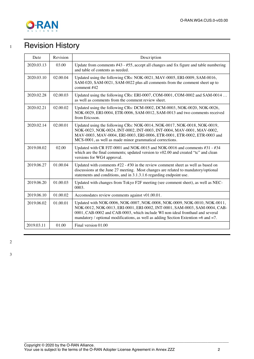
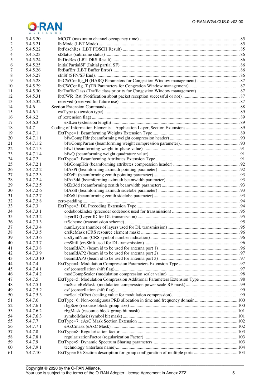
Revision History
Chapter 1 Introductory Material
1.1 Scope
1.2 References
1.2.1 Synchronization-specific Reference Documents
1.3 Definitions and Abbreviations and Conventions
1.3.1 Definitions
1.3.2 Abbreviations
1.3.3 Document Conventions
1.3.3.1 Fields and Bitmasks in Messages
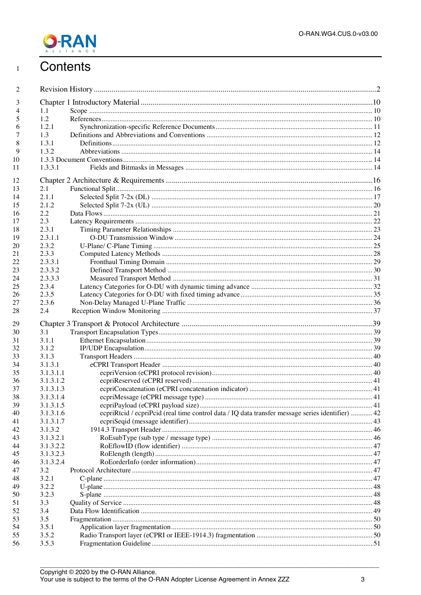
Chapter 2 Architecture & Requirements
2.1 Functional Split
2.1.1 Selected Split 7-2x (DL)
2.1.2 Selected Split 7-2x (UL)
2.2 Data Flows
2.3 Latency Requirements
2.3.1 Timing Parameter Relationships
2.3.1.1 O-DU Transmission Window
2.3.2 U-Plane/ C-Plane Timing
2.3.3 Computed Latency Methods
2.3.3.1 Fronthaul Timing Domain
2.3.3.2 Defined Transport Method
2.3.3.3 Measured Transport Method
2.3.4 Latency Categories for O-DU with dynamic timing advance
2.3.5 Latency Categories for O-DU with fixed timing advance
2.3.6 Non-Delay Managed U-Plane Traffic
2.4 Reception Window Monitoring
Chapter 3 Transport & Protocol Architecture
3.1 Transport Encapsulation Types
3.1.1 Ethernet Encapsulation
3.1.2 IP/UDP Encapsulation
3.1.3 Transport Headers
3.1.3.1 eCPRI Transport Header
3.1.3.1.1 ecpriVersion (eCPRI protocol revision)
3.1.3.1.2 ecpriReserved (eCPRI reserved)
3.1.3.1.3 ecpriConcatenation (eCPRI concatenation indicator)
3.1.3.1.4 ecpriMessage (eCPRI message type)
3.1.3.1.5 ecpriPayload (eCPRI payload size)
3.1.3.1.6 ecpriRtcid / ecpriPcid (real time control data / IQ data transfer message series identifier)
3.1.3.1.7 ecpriSeqid (message identifier)
3.1.3.2 1914.3 Transport Header
3.1.3.2.1 RoEsubType (sub type / message type)
3.1.3.2.2 RoEflowID (flow identifier)
3.1.3.2.3 RoElength (length)
3.1.3.2.4 RoEorderInfo (order information)
3.2 Protocol Architecture
3.2.1 C-plane
3.2.2 U-plane
3.2.3 S-plane
3.3 Quality of Service
3.4 Data Flow Identification
3.5 Fragmentation
3.5.1 Application layer fragmentation
3.5.2 Radio Transport layer (eCPRI or IEEE-1914.3) fragmentation
3.5.3 Fragmentation Guideline
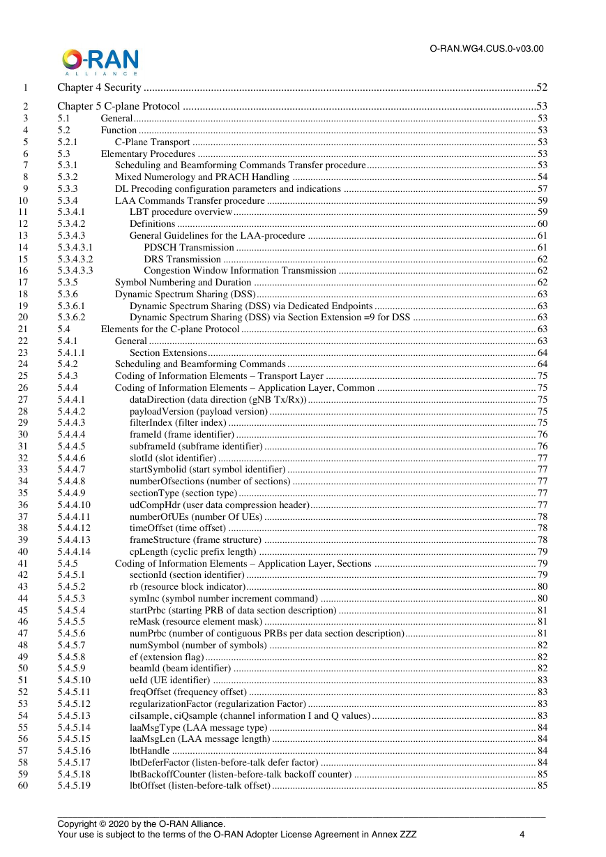
Chapter 4 Security
Chapter 5 C-plane Protocol
5.1 General
5.2 Function
5.2.1 C-Plane Transport
5.3 Elementary Procedures
5.3.1 Scheduling and Beamforming Commands Transfer procedure
5.3.2 Mixed Numerology and PRACH Handling
5.3.3 DL Precoding configuration parameters and indications
5.3.4 LAA Commands Transfer procedure
5.3.4.1 LBT procedure overview
5.3.4.2 Definitions
5.3.4.3 General Guidelines for the LAA-procedure
5.3.4.3.1 PDSCH Transmission
5.3.4.3.2 DRS Transmission
5.3.4.3.3 Congestion Window Information Transmission
5.3.5 Symbol Numbering and Duration
5.3.6 Dynamic Spectrum Sharing (DSS)
5.3.6.1 Dynamic Spectrum Sharing (DSS) via Dedicated Endpoints
5.3.6.2 Dynamic Spectrum Sharing (DSS) via Section Extension =9 for DSS
5.4 Elements for the C-plane Protocol
5.4.1 General
5.4.1.1 Section Extensions
5.4.2 Scheduling and Beamforming Commands
5.4.3 Coding of Information Elements – Transport Layer
5.4.4 Coding of Information Elements – Application Layer, Common
5.4.4.1 dataDirection (data direction (gNB Tx/Rx))
5.4.4.2 payloadVersion (payload version)
5.4.4.3 filterIndex (filter index)
5.4.4.4 frameId (frame identifier)
5.4.4.5 subframeId (subframe identifier)
5.4.4.6 slotId (slot identifier)
5.4.4.7 startSymbolid (start symbol identifier)
5.4.4.8 numberOfsections (number of sections)
5.4.4.9 sectionType (section type)
5.4.4.10 udCompHdr (user data compression header)
5.4.4.11 numberOfUEs (number Of UEs)
5.4.4.12 timeOffset (time offset)
5.4.4.13 frameStructure (frame structure)
5.4.4.14 cpLength (cyclic prefix length)
5.4.5 Coding of Information Elements – Application Layer, Sections
5.4.5.1 sectionId (section identifier)
5.4.5.2 rb (resource block indicator)
5.4.5.3 symInc (symbol number increment command)
5.4.5.4 startPrbc (starting PRB of data section description)
5.4.5.5 reMask (resource element mask)
5.4.5.6 numPrbc (number of contiguous PRBs per data section description)
5.4.5.7 numSymbol (number of symbols)
5.4.5.8 ef (extension flag)
5.4.5.9 beamId (beam identifier)
5.4.5.10 ueId (UE identifier)
5.4.5.11 freqOffset (frequency offset)
5.4.5.12 regularizationFactor (regularization Factor)
5.4.5.13 ciIsample, ciQsample (channel information I and Q values)
5.4.5.14 laaMsgType (LAA message type)
5.4.5.15 laaMsgLen (LAA message length)
5.4.5.16 lbtHandle
5.4.5.17 lbtDeferFactor (listen-before-talk defer factor)
5.4.5.18 lbtBackoffCounter (listen-before-talk backoff counter)
5.4.5.19 lbtOffset (listen-before-talk offset)
5.4.5.20 MCOT (maximum channel occupancy time)
5.4.5.21 lbtMode (LBT Mode)
5.4.5.22 lbtPdschRes (LBT PDSCH Result)
5.4.5.23 sfStatus (subframe status)
5.4.5.24 lbtDrsRes (LBT DRS Result)
5.4.5.25 initialPartialSF (Initial partial SF)
5.4.5.26 lbtBufErr (LBT Buffer Error)
5.4.5.27 sfnSf (SFN/SF End)
5.4.5.28 lbtCWConfig_H (HARQ Parameters for Congestion Window management)
5.4.5.29 lbtCWConfig_T (TB Parameters for Congestion Window management)
5.4.5.30 lbtTrafficClass (Traffic class priority for Congestion Window management)
5.4.5.31 lbtCWR_Rst (Notification about packet reception successful or not)
5.4.5.32 reserved (reserved for future use)
5.4.6 Section Extension Commands
5.4.6.1 extType (extension type)
5.4.6.2 ef (extension flag)
5.4.6.3 extLen (extension length)
5.4.7 Coding of Information Elements – Application Layer, Section Extensions
5.4.7.1 ExtType=1: Beamforming Weights Extension Type
5.4.7.1.1 bfwCompHdr (beamforming weight compression header)
5.4.7.1.2 bfwCompParam (beamforming weight compression parameter)
5.4.7.1.3 bfwI (beamforming weight in-phase value)
5.4.7.1.4 bfwQ (beamforming weight quadrature value)
5.4.7.2 ExtType=2: Beamforming Attributes Extension Type
5.4.7.2.1 bfaCompHdr (beamforming attributes compression header)
5.4.7.2.2 bfAzPt (beamforming azimuth pointing parameter)
5.4.7.2.3 bfZePt (beamforming zenith pointing parameter)
5.4.7.2.4 bfAz3dd (beamforming azimuth beamwidth parameter)
5.4.7.2.5 bfZe3dd (beamforming zenith beamwidth parameter)
5.4.7.2.6 bfAzSl (beamforming azimuth sidelobe parameter)
5.4.7.2.7 bfZeSl (beamforming zenith sidelobe parameter)
5.4.7.2.8 zero-padding
5.4.7.3 ExtType=3: DL Precoding Extension Type
5.4.7.3.1 codebookIndex (precoder codebook used for transmission)
5.4.7.3.2 layerID (Layer ID for DL transmission)
5.4.7.3.3 txScheme (transmission scheme)
5.4.7.3.4 numLayers (number of layers used for DL transmission)
5.4.7.3.5 crsReMask (CRS resource element mask)
5.4.7.3.6 crsSymlNum (CRS symbol number indication)
5.4.7.3.7 crsShift (crsShift used for DL transmission)
5.4.7.3.8 beamIdAP1 (beam id to be used for antenna port 1)
5.4.7.3.9 beamIdAP2 (beam id to be used for antenna port 2)
5.4.7.3.10 beamIdAP3 (beam id to be used for antenna port 3)
5.4.7.4 ExtType=4: Modulation Compression Parameters Extension Type
5.4.7.4.1 csf (constellation shift flag)
5.4.7.4.2 modCompScaler (modulation compression scaler value)
5.4.7.5 ExtType=5: Modulation Compression Additional Parameters Extension Type
5.4.7.5.1 mcScaleReMask (modulation compression power scale RE mask)
5.4.7.5.2 csf (constellation shift flag)
5.4.7.5.3 mcScaleOffset (scaling value for modulation compression)
5.4.7.6 ExtType=6: Non-contiguous PRB allocation in time and frequency domain
5.4.7.6.1 rbgSize (resource block group size)
5.4.7.6.2 rbgMask (resource block group bit mask)
5.4.7.6.3 symbolMask (symbol bit mask)
5.4.7.7 ExtType=7: eAxC Mask Section Extension
5.4.7.7.1 eAxCmask (eAxC Mask)
5.4.7.8 ExtType=8: Regularization factor
5.4.7.8.1 regularizationFactor (regularization Factor)
5.4.7.9 ExtType=9: Dynamic Spectrum Sharing parameters
5.4.7.9.1 technology (interface name)
5.4.7.10 ExtType=10: Section description for group configuration of multiple ports
5.4.7.10.1 beamGroupType
5.4.7.10.2 numPortc
5.4.7.10.3 Interaction with other Section Extensions
5.4.7.11 ExtType=11: Flexible Beamforming Weights Extension Type
5.4.7.11.1 bfwCompHdr (beamforming weight compression header)
5.4.7.11.2 bfwCompParam for PRB bundle x (beamforming weight compression parameter)
5.4.7.11.3 numBundPrb (Number of bundled PRBs per beamforming weights)
5.4.7.11.4 bfwI (beamforming weight in-phase value).
5.4.7.11.5 bfwQ (beamforming weight quadrature value)
5.4.7.11.6 disableBFWs (disable beamforming weights).
5.4.7.11.8 RAD (Reset After PRB Discontinuity)
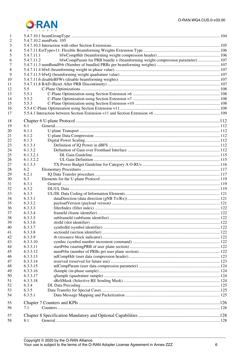
5.5 C-Plane Optimizations
5.5.1 C-Plane Optimization using Section Extension =6
5.5.2 C-Plane Optimization using Section Extension =7
5.5.3 C-Plane Optimization using Section Extension =10
5.5.4 C-Plane Optimization using Section Extension =11
5.5.4.1 Interaction between Section Extension =11 and Section Extension =6
Chapter 6 U-plane Protocol
6.1 General
6.1.1 U-plane Transport
6.1.2 U-plane Data Compression
6.1.3 Digital Power Scaling
6.1.3.1 Definition of IQ Power in dBFS
6.1.3.2 Definition of Gain over Fronthaul Interface
6.1.3.2.1 DL Gain Guideline
6.1.3.2.2 UL Gain Definition
6.1.3.3 TX Power Budget Guideline for Category A O-RUs
6.2 Elementary Procedures
6.2.1 IQ Data Transfer procedure
6.3 Elements for the U-plane Protocol
6.3.1 General
6.3.2 DL/UL Data
6.3.3 UL/DL Data Coding of Information Elements
6.3.3.1 dataDirection (data direction (gNB Tx/Rx))
6.3.3.2 payloadVersion (payload version)
6.3.3.3 filterIndex (filter index)
6.3.3.4 frameId (frame identifier)
6.3.3.5 subframeId (subframe identifier)
6.3.3.6 slotId (slot identifier)
6.3.3.7 symbolId (symbol identifier)
6.3.3.8 sectionId (section identifier)
6.3.3.9 rb (resource block indicator)
6.3.3.10 symInc (symbol number increment command)
6.3.3.11 startPrbu (startingPRB of user plane section)
6.3.3.12 numPrbu (number of PRBs per user plane section)
6.3.3.13 udCompHdr (user data compression header)
6.3.3.14 reserved (reserved for future use)
6.3.3.15 udCompParam (user data compression parameter)
6.3.3.16 iSample (in-phase sample)
6.3.3.17 qSample (quadrature sample)
6.3.3.18 sReSMask (Selective RE Sending Mask)
6.3.4 DL Data Precoding
6.3.5 Data Transfer for Special Cases
6.3.5.1 Data Message Mapping and Packetization
Chapter 7 Counters and KPIs
7.1 Counters
Chapter 8 Specification Mandatory and Optional Capabilities
8.1 General
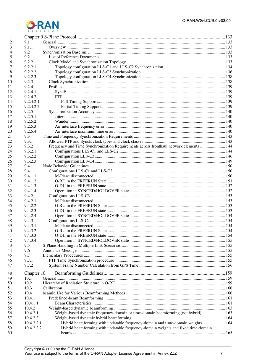
Chapter 9 S-Plane Protocol
9.1 General
9.1.1 Overview
9.2 Synchronization Baseline
9.2.1 List of Reference Documents
9.2.2 Clock Model and Synchronization Topology
9.2.2.1 Topology configuration LLS-C1 and LLS-C2 Synchronization
9.2.2.2 Topology configuration LLS-C3 Synchronization
9.2.2.3 Topology configuration LLS-C4 Synchronization
9.2.3 Clock Synchronization
9.2.4 Profiles
9.2.4.1 SyncE
9.2.4.2 PTP
9.2.4.2.1 Full Timing Support
9.2.4.2.2 Partial Timing Support
9.2.5 Synchronization Accuracy
9.2.5.1 Jitter
9.2.5.2 Wander
9.2.5.3 Air interface frequency error
9.2.5.4 Air interface maximum time error
9.3 Time and Frequency Synchronization Requirements
9.3.1 Allowed PTP and SyncE clock types and clock classes
9.3.2 Frequency and Time Synchronization Requirements across fronthaul network elements
9.3.2.1 Configurations LLS-C1 and LLS-C2
9.3.2.2 Configuration LLS-C3
9.3.2.3 Configuration LLS-C4
9.4 Node Behavior Guidelines
9.4.1 Configurations LLS-C1 and LLS-C2
9.4.1.1 M-Plane disconnected
9.4.1.2 O-RU in the FREERUN State
9.4.1.3 O-DU in the FREERUN state
9.4.1.4 Operation in SYNCED/HOLDOVER state
9.4.2 Configurations LLS-C3
9.4.2.1 M-Plane disconnected
9.4.2.2 O-RU in the FREERUN State
9.4.2.3 O-DU in the FREERUN state
9.4.2.4 Operation in SYNCED/HOLDOVER state
9.4.3 Configurations LLS-C4
9.4.3.1 M-Plane disconnected
9.4.3.2 O-RU in the FREERUN State
9.4.3.3 O-DU in the FREERUN state
9.4.3.4 Operation in SYNCED/HOLDOVER state
9.5 S-Plane Handling in Multiple Link Scenarios
9.6 Announce Messages
9.7 Elementary Procedures
9.7.1 PTP Time Synchronization procedure
9.7.2 System Frame Number Calculation from GPS Time
Chapter 10 Beamforming Guidelines
10.1 General
10.2 Hierarchy of Radiation Structure in O-RU
10.3 Calibration
10.4 beamId Use for Various Beamforming Methods
10.4.1 Predefined-beam Beamforming
10.4.1.1 Beam Characteristics
10.4.2 Weight-based dynamic beamforming
10.4.2.1 Weight-based dynamic frequency-domain or time-domain beamforming (not hybrid)
10.4.2.2 Weight-based dynamic hybrid beamforming
10.4.2.2.1 Hybrid beamforming with updatable frequency-domain and time-domain weights
10.4.2.2.2 Hybrid beamforming with updatable frequency-domain weights and fixed time-domain beams
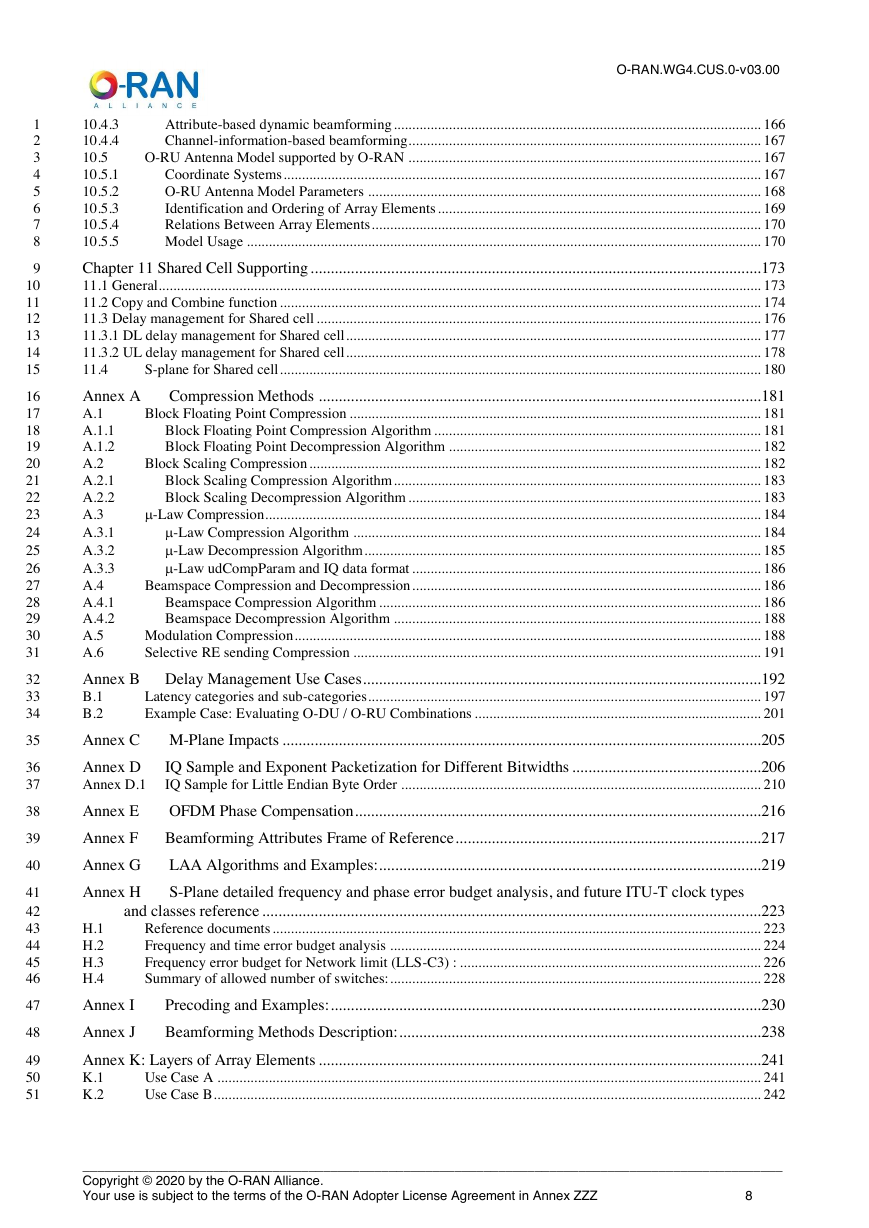
10.4.3 Attribute-based dynamic beamforming
10.4.4 Channel-information-based beamforming
10.5 O-RU Antenna Model supported by O-RAN
10.5.1 Coordinate Systems
10.5.2 O-RU Antenna Model Parameters
10.5.3 Identification and Ordering of Array Elements
10.5.4 Relations Between Array Elements
10.5.5 Model Usage
Chapter 11 Shared Cell Supporting
11.1 General
11.2 Copy and Combine function
11.3 Delay management for Shared cell
11.3.1 DL delay management for Shared cell
11.3.2 UL delay management for Shared cell
11.4 S-plane for Shared cell
Annex A Compression Methods
A.1 Block Floating Point Compression
A.1.1 Block Floating Point Compression Algorithm
A.1.2 Block Floating Point Decompression Algorithm
A.2 Block Scaling Compression
A.2.1 Block Scaling Compression Algorithm
A.2.2 Block Scaling Decompression Algorithm
A.3 -Law Compression
A.3.1 -Law Compression Algorithm
A.3.2 -Law Decompression Algorithm
A.3.3 -Law udCompParam and IQ data format
A.4 Beamspace Compression and Decompression
A.4.1 Beamspace Compression Algorithm
A.4.2 Beamspace Decompression Algorithm
A.5 Modulation Compression
A.6 Selective RE sending Compression
Annex B Delay Management Use Cases
B.1 Latency categories and sub-categories
B.2 Example Case: Evaluating O-DU / O-RU Combinations
Annex C M-Plane Impacts
Annex D IQ Sample and Exponent Packetization for Different Bitwidths
Annex D.1 IQ Sample for Little Endian Byte Order
Annex E OFDM Phase Compensation
Annex F Beamforming Attributes Frame of Reference
Annex G LAA Algorithms and Examples:
Annex H S-Plane detailed frequency and phase error budget analysis, and future ITU-T clock types and classes reference
H.1 Reference documents
H.2 Frequency and time error budget analysis
H.3 Frequency error budget for Network limit (LLS-C3) :
H.4 Summary of allowed number of switches:
Annex I Precoding and Examples:
Annex J Beamforming Methods Description:
Annex K: Layers of Array Elements
K.1 Use Case A
K.2 Use Case B
Appendix L: Considerations when operating in non-ideal transport environments
L.1 Deployment Scenarios and Performance Considerations
L.1.1 Low Impact
L.1.2 Medium Impact
L.1.3 High Impact
L.2 HARQ
L.2.1 Synchronous HARQ
L.2.1.1 HARQ Interleaving
L.2.1.2 Predictive HARQ
L.2.2 Asynchronous HARQ Considerations
L.3 RACH Considerations
L.3.1 Non-Ideal Fronthaul RACH Designs
L.3.1.1 Option-1: Semi-persistent Resource allocation
L.3.1.2 Option-2: RACH retransmission estimation
L.4 Other Latency Related Considerations
L.5 Bandwidth Limitation Considerations
Annex ZZZ : O-RAN Adopter License Agreement
Section 1: DEFINITIONS
Section 2: COPYRIGHT LICENSE
Section 3: FRAND LICENSE
Section 4: TERM AND TERMINATION
Section 5: CONFIDENTIALITY
Section 6: INDEMNIFICATION
Section 7: LIMITATIONS ON LIABILITY; NO WARRANTY
Section 8: ASSIGNMENT
Section 9: THIRD-PARTY BENEFICIARY RIGHTS
Section 10: BINDING ON AFFILIATES
Section 11: GENERAL


 2023年江西萍乡中考道德与法治真题及答案.doc
 2012年重庆南川中考生物真题及答案.doc
 2013年江西师范大学地理学综合及文艺理论基础考研真题.doc
 2020年四川甘孜小升初语文真题及答案I卷.doc
 2020年注册岩土工程师专业基础考试真题及答案.doc
 2023-2024学年福建省厦门市九年级上学期数学月考试题及答案.doc
 2021-2022学年辽宁省沈阳市大东区九年级上学期语文期末试题及答案.doc
 2022-2023学年北京东城区初三第一学期物理期末试卷及答案.doc
 2018上半年江西教师资格初中地理学科知识与教学能力真题及答案.doc
 2012年河北国家公务员申论考试真题及答案-省级.doc
 2020-2021学年江苏省扬州市江都区邵樊片九年级上学期数学第一次质量检测试题及答案.doc
 2022下半年黑龙江教师资格证中学综合素质真题及答案.doc