logo资料库

RTL8762CJ(F)_RTL8762CK(F)_Datasheet.pdf

第1页 / 共52页
第2页 / 共52页
第3页 / 共52页
第4页 / 共52页
第5页 / 共52页
第6页 / 共52页
第7页 / 共52页
第8页 / 共52页
资料共52页,剩余部分请下载后查看
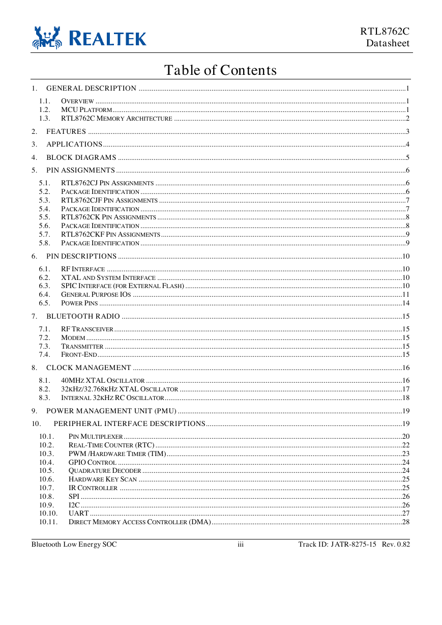
1. General Description
1.1. Overview
1.2. MCU Platform
1.3. RTL8762C Memory Architecture
2. Features
3. Applications
4. Block Diagrams
5. Pin Assignments
5.1. RTL8762CJ Pin Assignments
5.2. Package Identification
5.3. RTL8762CJF Pin Assignments
5.4. Package Identification
5.5. RTL8762CK Pin Assignments
5.6. Package Identification
5.7. RTL8762CKF Pin Assignments
5.8. Package Identification
6. Pin Descriptions
6.1. RF Interface
6.2. XTAL and System Interface
6.3. SPIC Interface (for External Flash)
6.4. General Purpose IOs
6.5. Power Pins
7. Bluetooth Radio
7.1. RF Transceiver
7.2. Modem
7.3. Transmitter
7.4. Front-End
8. Clock Management
8.1. 40MHz XTAL Oscillator
8.2. 32kHz/32.768kHz XTAL Oscillator
8.3. Internal 32kHz RC Oscillator
9. Power Management Unit (PMU)
10. Peripheral Interface Descriptions
10.1. Pin Multiplexer
10.2. Real-Time Counter (RTC)
10.3. PWM /Hardware Timer (TIM)
10.4. GPIO Control
10.5. Quadrature Decoder
10.6. Hardware Key Scan
10.7. IR Controller
10.8. SPI
10.9. I2C
10.10. UART
10.11. Direct Memory Access Controller (DMA)
10.12. I8080 Interface for LCD Controller
10.13. AUXADC
10.14. Microphone Interface
10.15. Audio Output Interface
11. Electrical and Thermal Characteristics
11.1. Temperature Limit Ratings
11.2. Power Supply DC Characteristics
11.3. Switching Regulator Characteristics
11.4. RTX LDO Characteristics
11.5. Synthesizer LDO Characteristics
11.6. ESD Characteristics
11.7. AUXADC Characteristics
11.8. Microphone Interface Characteristics
11.9. Radio Characteristics
11.10. Digital IO Pin DC Characteristics
11.11. Boot Sequence
11.12. UART Characteristics
11.13. I2C Timing Characteristics
11.14. Power Consumption
11.14.1. Low Power Mode
11.14.2. Active Mode
12. Mechanical Dimensions
12.1. RTL8762CJ/RTL8762CJF: Plastic Quad Flat No-Lead Package 40 Leads 5x5mm Outline
12.2. RTL8762CJ/RTL8762CJF Mechanical Dimensions Notes
12.3. RTL8762CK/RTL8762CKF: Plastic Quad Flat No-Lead Package 48 Leads 6x6mm Outline
12.4. RTL8762CK/RTL8762CKF Mechanical Dimensions Notes
13. Reflow Profile
14. Ordering Information
RTL8762CJ / RTL8762CJF RTL8762CK / RTL8762CKF BLUETOOTH LOW ENERGY SOC PRELIMINARY DATASHEET (CONFIDENTIAL: Development Partners Only) Rev. 0.82 28 November 2018 Track ID: JATR-8275-15 Realtek Semiconductor Corp. No. 2, Innovation Road II, Hsinchu Science Park, Hsinchu 300, Taiwan Tel.: +886-3-578-0211. Fax: +886-3-577-6047 www.realtek.com
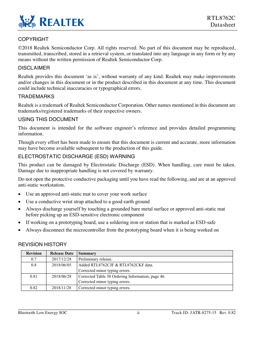
COPYRIGHT RTL8762C Datasheet ©2018 Realtek Semiconductor Corp. All rights reserved. No part of this document may be reproduced, transmitted, transcribed, stored in a retrieval system, or translated into any language in any form or by any means without the written permission of Realtek Semiconductor Corp. DISCLAIMER Realtek provides this document ‘as is’, without warranty of any kind. Realtek may make improvements and/or changes in this document or in the product described in this document at any time. This document could include technical inaccuracies or typographical errors. TRADEMARKS Realtek is a trademark of Realtek Semiconductor Corporation. Other names mentioned in this document are trademarks/registered trademarks of their respective owners. USING THIS DOCUMENT This document is intended for the software engineer’s reference and provides detailed programming information. Though every effort has been made to ensure that this document is current and accurate, more information may have become available subsequent to the production of this guide. ELECTROSTATIC DISCHARGE (ESD) WARNING This product can be damaged by Electrostatic Discharge (ESD). When handling, care must be taken. Damage due to inappropriate handling is not covered by warranty. Do not open the protective conductive packaging until you have read the following, and are at an approved anti-static workstation.  Use an approved anti-static mat to cover your work surface  Use a conductive wrist strap attached to a good earth ground  Always discharge yourself by touching a grounded bare metal surface or approved anti-static mat before picking up an ESD-sensitive electronic component  If working on a prototyping board, use a soldering iron or station that is marked as ESD-safe  Always disconnect the microcontroller from the prototyping board when it is being worked on REVISION HISTORY Revision Release Date Summary 0.7 0.8 2017/12/28 Preliminary release. 2018/06/05 Added RTL8762CJF & RTL8762CKF data. Corrected minor typing errors. 0.81 2018/06/28 Corrected Table 30 Ordering Information, page 46. Corrected minor typing errors. 0.82 2018/11/28 Corrected minor typing errors. Bluetooth Low Energy SOC ii Track ID: JATR-8275-15 Rev. 0.82
Table of Contents RTL8762C Datasheet 1. GENERAL DESCRIPTION ............................................................................................................................................... 1 1.1. OVERVIEW ...................................................................................................................................................................... 1 1.2. MCU PLATFORM ............................................................................................................................................................. 1 1.3. RTL8762C MEMORY ARCHITECTURE ............................................................................................................................ 2 2. FEATURES .......................................................................................................................................................................... 3 3. APPLICATIONS .................................................................................................................................................................. 4 4. BLOCK DIAGRAMS .......................................................................................................................................................... 5 5. PIN ASSIGNMENTS ........................................................................................................................................................... 6 5.1. RTL8762CJ PIN ASSIGNMENTS ...................................................................................................................................... 6 5.2. PACKAGE IDENTIFICATION .............................................................................................................................................. 6 5.3. RTL8762CJF PIN ASSIGNMENTS .................................................................................................................................... 7 5.4. PACKAGE IDENTIFICATION .............................................................................................................................................. 7 5.5. RTL8762CK PIN ASSIGNMENTS ..................................................................................................................................... 8 5.6. PACKAGE IDENTIFICATION .............................................................................................................................................. 8 5.7. RTL8762CKF PIN ASSIGNMENTS ................................................................................................................................... 9 5.8. PACKAGE IDENTIFICATION .............................................................................................................................................. 9 6. PIN DESCRIPTIONS ........................................................................................................................................................ 10 6.1. RF INTERFACE .............................................................................................................................................................. 10 6.2. XTAL AND SYSTEM INTERFACE ................................................................................................................................... 10 6.3. SPIC INTERFACE (FOR EXTERNAL FLASH) .................................................................................................................... 10 6.4. GENERAL PURPOSE IOS ................................................................................................................................................ 11 6.5. POWER PINS .................................................................................................................................................................. 14 7. BLUETOOTH RADIO ...................................................................................................................................................... 15 7.1. RF TRANSCEIVER .......................................................................................................................................................... 15 7.2. MODEM ......................................................................................................................................................................... 15 TRANSMITTER ............................................................................................................................................................... 15 7.3. 7.4. FRONT-END ................................................................................................................................................................... 15 8. CLOCK MANAGEMENT ................................................................................................................................................ 16 8.1. 8.2. 8.3. 40MHZ XTAL OSCILLATOR ......................................................................................................................................... 16 32KHZ/32.768KHZ XTAL OSCILLATOR ....................................................................................................................... 17 INTERNAL 32KHZ RC OSCILLATOR ............................................................................................................................... 18 9. POWER MANAGEMENT UNIT (PMU) ........................................................................................................................ 19 10. PERIPHERAL INTERFACE DESCRIPTIONS ......................................................................................................... 19 10.1. PIN MULTIPLEXER ..................................................................................................................................................... 20 10.2. REAL-TIME COUNTER (RTC) .................................................................................................................................... 22 10.3. PWM /HARDWARE TIMER (TIM) .............................................................................................................................. 23 10.4. GPIO CONTROL ........................................................................................................................................................ 24 10.5. QUADRATURE DECODER ........................................................................................................................................... 24 10.6. HARDWARE KEY SCAN ............................................................................................................................................. 25 10.7. IR CONTROLLER ....................................................................................................................................................... 25 10.8. SPI ............................................................................................................................................................................ 26 10.9. I2C ............................................................................................................................................................................ 26 10.10. UART ....................................................................................................................................................................... 27 10.11. DIRECT MEMORY ACCESS CONTROLLER (DMA) ...................................................................................................... 28 Bluetooth Low Energy SOC iii Track ID: JATR-8275-15 Rev. 0.82
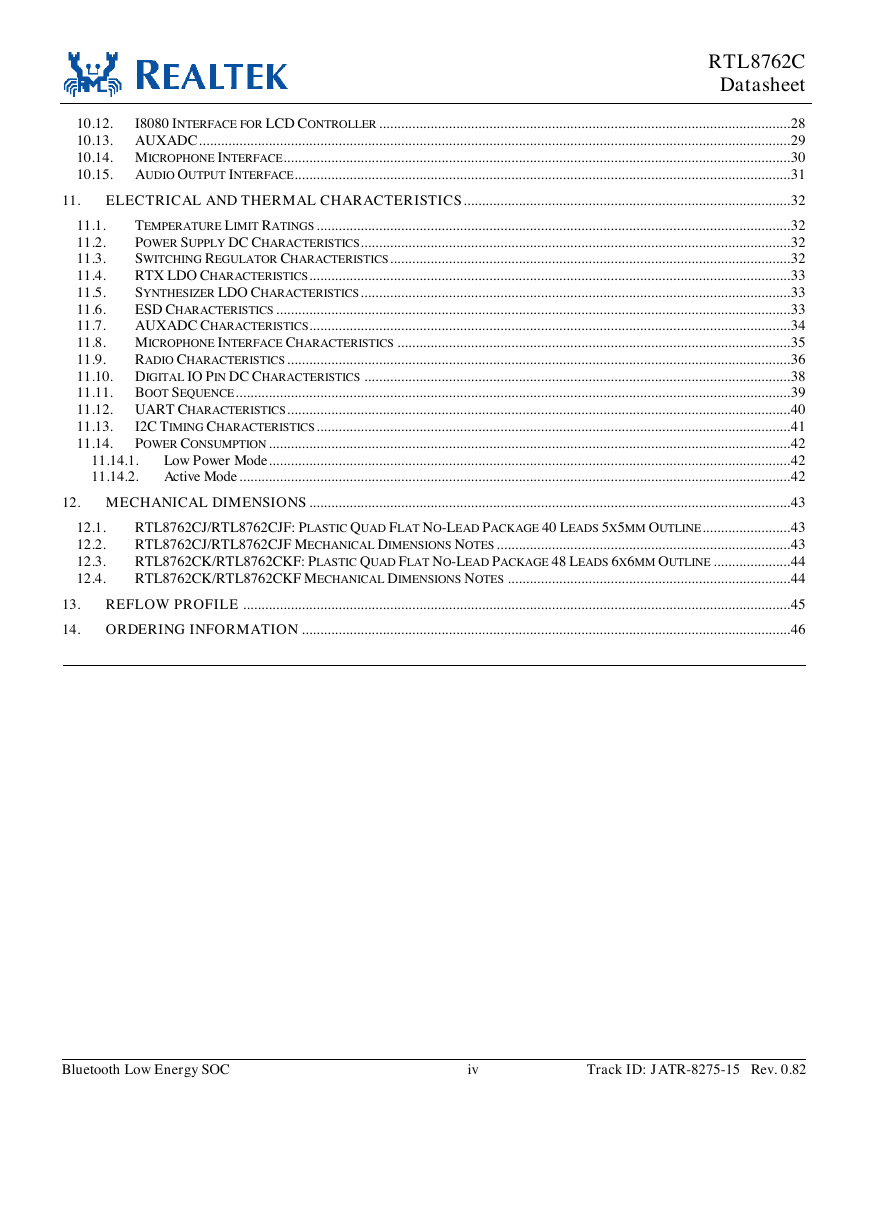
RTL8762C Datasheet 10.12. I8080 INTERFACE FOR LCD CONTROLLER ................................................................................................................ 28 10.13. AUXADC ................................................................................................................................................................. 29 10.14. MICROPHONE INTERFACE.......................................................................................................................................... 30 10.15. AUDIO OUTPUT INTERFACE ....................................................................................................................................... 31 11. ELECTRICAL AND THERMAL CHARACTERISTICS ......................................................................................... 32 TEMPERATURE LIMIT RATINGS ................................................................................................................................. 32 11.1. POWER SUPPLY DC CHARACTERISTICS ..................................................................................................................... 32 11.2. SWITCHING REGULATOR CHARACTERISTICS ............................................................................................................. 32 11.3. RTX LDO CHARACTERISTICS ................................................................................................................................... 33 11.4. SYNTHESIZER LDO CHARACTERISTICS ..................................................................................................................... 33 11.5. ESD CHARACTERISTICS ............................................................................................................................................ 33 11.6. 11.7. AUXADC CHARACTERISTICS................................................................................................................................... 34 11.8. MICROPHONE INTERFACE CHARACTERISTICS ........................................................................................................... 35 11.9. RADIO CHARACTERISTICS ......................................................................................................................................... 36 11.10. DIGITAL IO PIN DC CHARACTERISTICS .................................................................................................................... 38 11.11. BOOT SEQUENCE ....................................................................................................................................................... 39 11.12. UART CHARACTERISTICS ......................................................................................................................................... 40 I2C TIMING CHARACTERISTICS ................................................................................................................................. 41 11.13. POWER CONSUMPTION .............................................................................................................................................. 42 11.14. Low Power Mode .............................................................................................................................................. 42 Active Mode ...................................................................................................................................................... 42 11.14.1. 11.14.2. 12. MECHANICAL DIMENSIONS ................................................................................................................................... 43 12.1. 12.2. 12.3. 12.4. RTL8762CJ/RTL8762CJF: PLASTIC QUAD FLAT NO-LEAD PACKAGE 40 LEADS 5X5MM OUTLINE ........................ 43 RTL8762CJ/RTL8762CJF MECHANICAL DIMENSIONS NOTES ................................................................................ 43 RTL8762CK/RTL8762CKF: PLASTIC QUAD FLAT NO-LEAD PACKAGE 48 LEADS 6X6MM OUTLINE ..................... 44 RTL8762CK/RTL8762CKF MECHANICAL DIMENSIONS NOTES ............................................................................. 44 13. REFLOW PROFILE ..................................................................................................................................................... 45 14. ORDERING INFORMATION ..................................................................................................................................... 46 Bluetooth Low Energy SOC iv Track ID: JATR-8275-15 Rev. 0.82
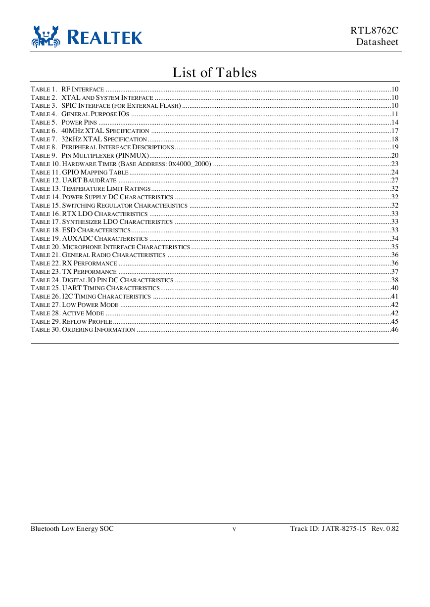
List of Tables RTL8762C Datasheet TABLE 1. RF INTERFACE ............................................................................................................................................................. 10 TABLE 2. XTAL AND SYSTEM INTERFACE .................................................................................................................................. 10 TABLE 3. SPIC INTERFACE (FOR EXTERNAL FLASH) ................................................................................................................... 10 TABLE 4. GENERAL PURPOSE IOS ............................................................................................................................................... 11 TABLE 5. POWER PINS ................................................................................................................................................................. 14 TABLE 6. 40MHZ XTAL SPECIFICATION .................................................................................................................................... 17 TABLE 7. 32KHZ XTAL SPECIFICATION ...................................................................................................................................... 18 TABLE 8. PERIPHERAL INTERFACE DESCRIPTIONS ....................................................................................................................... 19 TABLE 9. PIN MULTIPLEXER (PINMUX)..................................................................................................................................... 20 TABLE 10. HARDWARE TIMER (BASE ADDRESS: 0X4000_2000) .................................................................................................. 23 TABLE 11. GPIO MAPPING TABLE ................................................................................................................................................ 24 TABLE 12. UART BAUDRATE ...................................................................................................................................................... 27 TABLE 13. TEMPERATURE LIMIT RATINGS .................................................................................................................................... 32 TABLE 14. POWER SUPPLY DC CHARACTERISTICS ....................................................................................................................... 32 TABLE 15. SWITCHING REGULATOR CHARACTERISTICS ............................................................................................................... 32 TABLE 16. RTX LDO CHARACTERISTICS ..................................................................................................................................... 33 TABLE 17. SYNTHESIZER LDO CHARACTERISTICS ....................................................................................................................... 33 TABLE 18. ESD CHARACTERISTICS ............................................................................................................................................... 33 TABLE 19. AUXADC CHARACTERISTICS ..................................................................................................................................... 34 TABLE 20. MICROPHONE INTERFACE CHARACTERISTICS .............................................................................................................. 35 TABLE 21. GENERAL RADIO CHARACTERISTICS ........................................................................................................................... 36 TABLE 22. RX PERFORMANCE ...................................................................................................................................................... 36 TABLE 23. TX PERFORMANCE ...................................................................................................................................................... 37 TABLE 24. DIGITAL IO PIN DC CHARACTERISTICS ....................................................................................................................... 38 TABLE 25. UART TIMING CHARACTERISTICS ............................................................................................................................... 40 TABLE 26. I2C TIMING CHARACTERISTICS ................................................................................................................................... 41 TABLE 27. LOW POWER MODE ..................................................................................................................................................... 42 TABLE 28. ACTIVE MODE ............................................................................................................................................................. 42 TABLE 29. REFLOW PROFILE ......................................................................................................................................................... 45 TABLE 30. ORDERING INFORMATION ............................................................................................................................................ 46 Bluetooth Low Energy SOC v Track ID: JATR-8275-15 Rev. 0.82
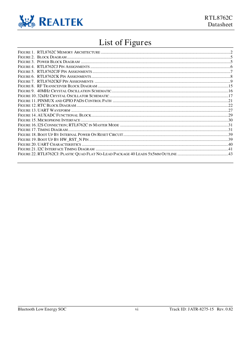
List of Figures RTL8762C Datasheet FIGURE 1. RTL8762C MEMORY ARCHITECTURE .......................................................................................................................... 2 FIGURE 2. BLOCK DIAGRAM .......................................................................................................................................................... 5 FIGURE 3. POWER BLOCK DIAGRAM ............................................................................................................................................. 5 FIGURE 4. RTL8762CJ PIN ASSIGNMENTS .................................................................................................................................... 6 FIGURE 5. RTL8762CJF PIN ASSIGNMENTS .................................................................................................................................. 7 FIGURE 6. RTL8762CK PIN ASSIGNMENTS ................................................................................................................................... 8 FIGURE 7. RTL8762CKF PIN ASSIGNMENTS ................................................................................................................................ 9 FIGURE 8. RF TRANSCEIVER BLOCK DIAGRAM ........................................................................................................................... 15 FIGURE 9. 40MHZ CRYSTAL OSCILLATION SCHEMATIC.............................................................................................................. 16 FIGURE 10. 32KHZ CRYSTAL OSCILLATOR SCHEMATIC ................................................................................................................ 17 FIGURE 11. PINMUX AND GPIO PADS CONTROL PATH ............................................................................................................. 21 FIGURE 12. RTC BLOCK DIAGRAM ............................................................................................................................................... 22 FIGURE 13. UART WAVEFORM .................................................................................................................................................... 27 FIGURE 14. AUXADC FUNCTIONAL BLOCK ................................................................................................................................. 29 FIGURE 15. MICROPHONE INTERFACE ........................................................................................................................................... 30 FIGURE 16. I2S CONNECTION; RTL8762C IN MASTER MODE ...................................................................................................... 31 FIGURE 17. TIMING DIAGRAM ....................................................................................................................................................... 31 FIGURE 18. BOOT UP BY INTERNAL POWER ON RESET CIRCUIT................................................................................................... 39 FIGURE 19. BOOT UP BY HW_RST_N PIN ................................................................................................................................... 39 FIGURE 20. UART CHARACTERISTICS .......................................................................................................................................... 40 FIGURE 21. I2C INTERFACE TIMING DIAGRAM ............................................................................................................................. 41 FIGURE 22. RTL8762CJ: PLASTIC QUAD FLAT NO-LEAD PACKAGE 40 LEADS 5X5MM OUTLINE ................................................ 43 Bluetooth Low Energy SOC vi Track ID: JATR-8275-15 Rev. 0.82
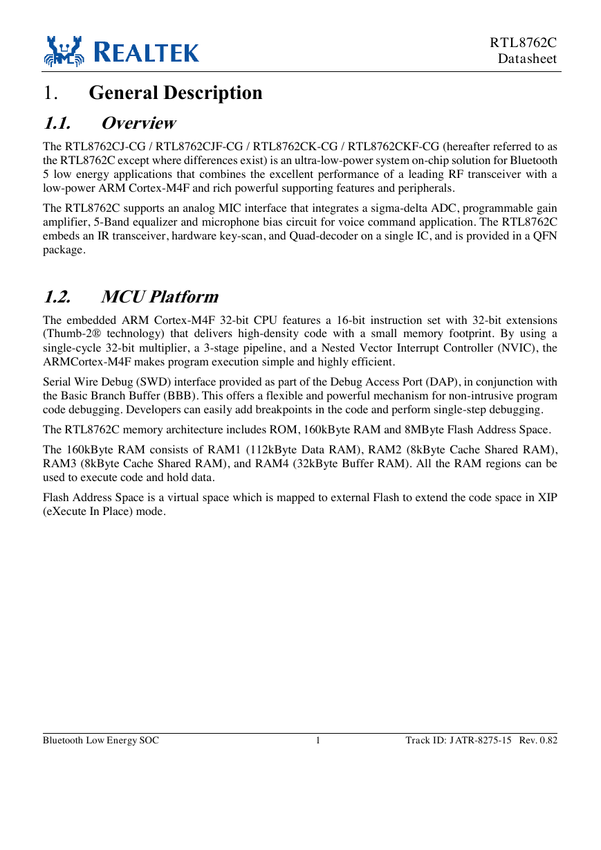
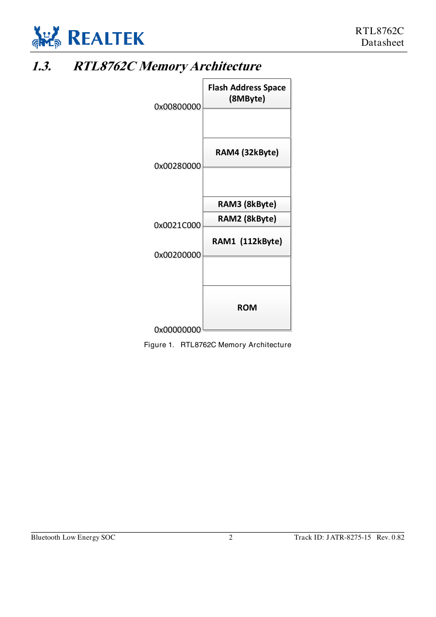
1. General Description 1.1. Overview RTL8762C Datasheet The RTL8762CJ-CG / RTL8762CJF-CG / RTL8762CK-CG / RTL8762CKF-CG (hereafter referred to as the RTL8762C except where differences exist) is an ultra-low-power system on-chip solution for Bluetooth 5 low energy applications that combines the excellent performance of a leading RF transceiver with a low-power ARM Cortex-M4F and rich powerful supporting features and peripherals. The RTL8762C supports an analog MIC interface that integrates a sigma-delta ADC, programmable gain amplifier, 5-Band equalizer and microphone bias circuit for voice command application. The RTL8762C embeds an IR transceiver, hardware key-scan, and Quad-decoder on a single IC, and is provided in a QFN package. 1.2. MCU Platform The embedded ARM Cortex-M4F 32-bit CPU features a 16-bit instruction set with 32-bit extensions (Thumb-2® technology) that delivers high-density code with a small memory footprint. By using a single-cycle 32-bit multiplier, a 3-stage pipeline, and a Nested Vector Interrupt Controller (NVIC), the ARMCortex-M4F makes program execution simple and highly efficient. Serial Wire Debug (SWD) interface provided as part of the Debug Access Port (DAP), in conjunction with the Basic Branch Buffer (BBB). This offers a flexible and powerful mechanism for non-intrusive program code debugging. Developers can easily add breakpoints in the code and perform single-step debugging. The RTL8762C memory architecture includes ROM, 160kByte RAM and 8MByte Flash Address Space. The 160kByte RAM consists of RAM1 (112kByte Data RAM), RAM2 (8kByte Cache Shared RAM), RAM3 (8kByte Cache Shared RAM), and RAM4 (32kByte Buffer RAM). All the RAM regions can be used to execute code and hold data. Flash Address Space is a virtual space which is mapped to external Flash to extend the code space in XIP (eXecute In Place) mode. Bluetooth Low Energy SOC 1 Track ID: JATR-8275-15 Rev. 0.82
1.3. RTL8762C Memory Architecture RTL8762C Datasheet Figure 1. RTL8762C Memory Architecture Bluetooth Low Energy SOC 2 Track ID: JATR-8275-15 Rev. 0.82 ROM RAM1 (112kByte)RAM2 (8kByte)RAM3 (8kByte)RAM4 (32kByte)Flash Address Space (8MByte)0x0021C0000x002000000x000000000x002800000x00800000
分享到:
收藏