Initial commissioning
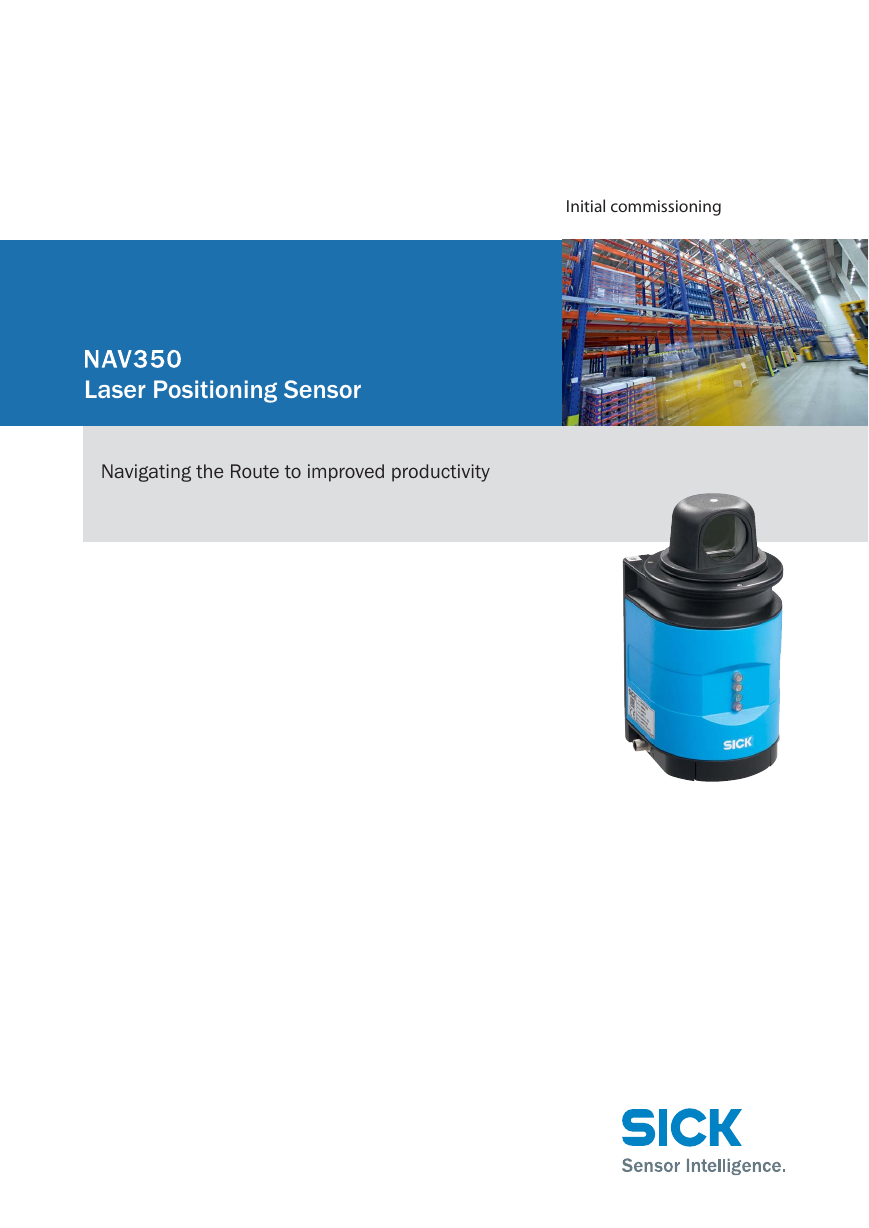
Laser Positioning Sensor
Navigating the Route to improved productivity
�
SoftwareStand
Operating Instructions
NAV350 Laser positioning sensor
Software version described
Function
Software/tool
NAV350
Firmware
Device specific software module
Device description NAV350
for SOPAS ET
Configuration software
SOPAS ET
Status
V 1.06
V 1.000 or higher
V 02.38 or higher
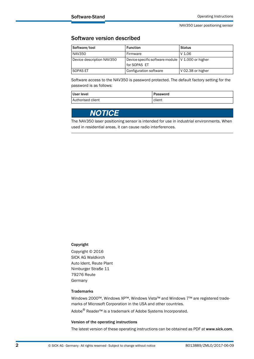
Software access to the NAV350 is password protected. The default factory setting for the
password is as follows:
User level
Authorised client
Password
client
The NAV350 laser positioning sensor is intended for use in industrial environments. When
used in residential areas, it can cause radio interferences.
Copyright
Copyright © 2016
SICK AG Waldkirch
Auto Ident, Reute Plant
Nimburger Straße 11
79276 Reute
Germany
Trademarks
Windows 2000™, Windows XP™, Windows Vista™ and Windows 7™ are registered trade-
marks of Microsoft Corporation in the USA and other countries.
Adobe® Reader™ is a trademark of Adobe Systems Incorporated.
Version of the operating instructions
The latest version of these operating instructions can be obtained as PDF at www.sick.com.
2
© SICK AG · Germany · All rights reserved · Subject to change without notice
8013889/ZML0/2017-06-09
�
Operating Instructions
SoftwareStand
NAV350
Table of content
1
About this document .......................................................................................................8
1.1
Function of this document .......................................................................................... 8
1.2
Target group ................................................................................................................ 8
1.3
Depth of information ................................................................................................... 8
1.4
Symbology used .......................................................................................................... 9
2
For your safety ..............................................................................................................10
2.1
Authorised personnel ................................................................................................ 10
2.2
Correct use ................................................................................................................ 11
2.3
General safety notes and protective measures ...................................................... 12
2.4
Quick stop and Quick restart .................................................................................... 13
2.5
Environmental protection ......................................................................................... 14
3
Product description ...................................................................................................... 15
3.1
Delivery ...................................................................................................................... 15
3.2
Construction of the NAV350 ..................................................................................... 16
3.3
Special features of the NAV350 ............................................................................... 18
3.4
Applications ............................................................................................................... 19
3.5
Operating principle of the NAV350 .......................................................................... 19
3.6
Landmark detection .................................................................................................. 23
3.7
Navigation .................................................................................................................. 24
3.8
Output of measured values ...................................................................................... 31
3.9
Integration of the NAV350 in an AGV’s control system .......................................... 31
3.10 Planning ..................................................................................................................... 36
Mounting ........................................................................................................................ 43
4
4.1
Overview of the mounting steps ............................................................................... 43
4.2
Preparations for mounting ........................................................................................ 43
4.3 Mounting and adjustment of the device ................................................................. 43
Dismantling the NAV350 .......................................................................................... 44
4.4
5
Electrical installation ................................................................................................... 45
Overview of the installation steps ............................................................................ 45
5.1
Connections of the NAV350 ..................................................................................... 45
5.2
Preparing the electrical installation ......................................................................... 46
5.3
5.4
Undertaking electrical installation on the NAV350 ................................................ 47
Commissioning and configuration ............................................................................. 50
6
Overview of the commissioning steps ..................................................................... 50
6.1
SOPAS ET configuration software ............................................................................ 51
6.2
6.3
Establish communication with the NAV350 ............................................................ 51
Initial commissioning ................................................................................................ 55
6.4
Connection and test measurement ......................................................................... 56
6.5
6.6
Loading reflector data ............................................................................................... 57
7
Maintenance ................................................................................................................. 58
7.1 Maintenance during operation ................................................................................. 58
Exchanging a NAV350 .............................................................................................. 59
7.2
8
Troubleshooting ............................................................................................................ 60
8.1
In the event of fault ................................................................................................... 60
8.2 Monitoring error and malfunction indications ......................................................... 60
Troubleshooting and rectification ............................................................................ 61
8.3
8.4
Detailed error analysis .............................................................................................. 61
SICK support .............................................................................................................. 62
8.5
8013889/ZML0/2017-06-09
© SICK AG · Germany · All rights reserved · Subject to change without notice
3
�
SoftwareStand
Operating Instructions
NAV350 Laser positioning sensor
Technical specifications .............................................................................................. 63
9
Data sheet NAV350 .................................................................................................. 63
9.1
Dimensional drawings .............................................................................................. 65
9.2
Annex ............................................................................................................................. 66
10
10.1 Overview of the annexes .......................................................................................... 66
10.2 Ordering information ................................................................................................ 66
10.3 Glossary ..................................................................................................................... 67
10.4 EC declaration of conformity .................................................................................... 68
4
© SICK AG · Germany · All rights reserved · Subject to change without notice
8013889/ZML0/2017-06-09
�
Operating Instructions
Verzeichnisse
NAV350
Abbreviations
CoLa Communication Language = proprietary SOPAS ET communication language
(ASCII = CoLa-A or binary = CoLa-B)
EEPROM Electrically Erasable Programmable Read-only Memory
Automated guided vehicle
AGV
LED Light Emitting Diode
RAM Random Access Memory = volatile memory with direct access
ROM Read-only Memory (permanent)
SOPAS ET SICK OPEN PORTAL for APPLICATION and SYSTEMS ENGINEERING TOOL = configuration
software for the configuration of the NAV350
8013889/ZML0/2017-06-09
© SICK AG · Germany · All rights reserved · Subject to change without notice
5
�
Verzeichnisse
Operating Instructions
NAV350 Laser positioning sensor
Tables
Target groups of this document .............................................................................. 8
Tab. 1:
Authorised personnel .............................................................................................10
Tab. 2:
Tab. 3:
Delivery ...................................................................................................................15
Tab. 4: Meaning of the LED status indicators ..................................................................17
Tab. 5:
Special features of the NAV350 ...........................................................................18
Typical remissions and scanning ranges ..............................................................22
Tab. 6:
Frame for the telegrams with ASCII coding ..........................................................32
Tab. 7:
Tab. 8:
Beam diameter at different distances from the NAV350 ...................................37
Tab. 9:
Pin assignment of the “Power” connection on the NAV350 ...............................46
Tab. 10: Pin assignment of the “Ethernet” connection on the NAV350 ...........................46
Tab. 11: Pin assignment of the “RS232” connection on the NAV350 ..............................46
Tab. 12: Maximum cable lengths for the supply voltage ...................................................47
Tab. 13: Maximum length of cable for the data interface .................................................47
Tab. 14: SOPAS ET default setting .......................................................................................51
Tab. 15: Password NAV350 .................................................................................................56
Tab. 16: Troubleshooting and rectification .........................................................................61
Tab. 17: Data sheet NAV350 ...............................................................................................63
Tab. 18: Consumables ..........................................................................................................66
6
© SICK AG · Germany · All rights reserved · Subject to change without notice
8013889/ZML0/2017-06-09
�
Operating Instructions
Verzeichnisse
NAV350
Figures
Laser output aperture on the NAV350 ................................................................ 13
Fig. 1:
Views of device ...................................................................................................... 16
Fig. 2:
Measuring principle of the NAV350 ..................................................................... 19
Fig. 3:
Principle of operation of the NAV350 .................................................................. 20
Fig. 4:
Diffuse reflection from objects ............................................................................. 21
Fig. 5:
Directional reflection from reflectors ................................................................... 21
Fig. 6:
Possible sources of errors during the measurement .......................................... 21
Fig. 7:
Beam diameter and distance between measured points at 0 to 100 m .......... 22
Fig. 8:
Fig. 9:
Landmark detection .............................................................................................. 23
Fig. 10: Determination of the position by the NAV350 by means of the detection of reflec-
tor placements ....................................................................................................... 24
Fig. 11:
Identification of reflectors in the operational status “continuous positioning” 25
Fig. 12: Radius of the detection window as a function of the distance .......................... 26
Fig. 13: Restricted action radius ........................................................................................ 27
Fig. 14:
Example for the definition of muted sectors ....................................................... 29
Fig. 15: Overlapping of two reflectors ................................................................................ 29
Fig. 16: Minimum distance from reflectors to other reflecting objects ........................... 30
Fig. 17: Output of measured values for truck loading ...................................................... 31
Fig. 18: Requesting an absolute position or landmark positions .................................... 32
Fig. 19:
Integration of the NAV350 in a navigation system ............................................. 33
Fig. 20: Pulse for synchronisation ...................................................................................... 34
Fig. 21:
Increase in the size of the beam and safety supplement .................................. 37
Fig. 22: Absolute and local coordinate system with angular position of the NAV350 ... 38
Fig. 23: Reflector height as a function of the distance from 0 to 70 m .......................... 39
Fig. 24: Correct, asymmetrical placement and incorrect, symmetrical placement of reflec-
tors .......................................................................................................................... 40
Fig. 25: Common usage of the reflectors from two neighbouring layers ........................ 42
Fig. 26: Connections of the NAV350 ................................................................................. 45
Fig. 27: Connection of the voltage supply ......................................................................... 48
Fig. 28:
Ethernet connection .............................................................................................. 48
Fig. 29: Wiring the RS232 interface .................................................................................. 48
Fig. 30: RS232 connection ................................................................................................. 49
Fig. 31:
IP communication with fixed IP address .............................................................. 53
Fig. 32: Configuring with AutoIP ......................................................................................... 54
Fig. 33: Principle of data storage ....................................................................................... 55
Fig. 34:
Example text file with reflector data ..................................................................... 57
Fig. 35: Window in the scanner head on the NAV350 ..................................................... 58
Abb. 36: Dimensions NAV350 ............................................................................................. 65
Fig. 37:
Illustration containing the EU declaration of conformity .................................... 68
8013889/ZML0/2017-06-09
© SICK AG · Germany · All rights reserved · Subject to change without notice
7
�
Verzeichnisse
Operating Instructions
NAV350 Laser positioning sensor
1
About this document
Please read this chapter carefully before working with this documentation and the laser po-
sitioning sensor NAV350.
Function of this document
1.1
These operating instructions are designed to address the technical personnel in regards to
safe mounting, electrical installation, configuration, commissioning and maintenance of the
following laser positioning sensor.
Target group
1.2
The intended target group for this document is people in the following positions:
Activities
Mounting, electrical installation,
maintenance and replacement
Commissioning, operation and con-
figuration
Tab. 1:
Target groups of this document
Target group
Factory electricians and service engineers
Technicians and engineers
Depth of information
Product description
troubleshooting and rectification
Electrical installation
Commissioning and configuration
1.3
These operating instructions contain the following information on the NAV350:
•
• Mounting
•
•
• maintenance
•
• Ordering information
•
Planning and using a laser positioning sensor such as the NAV350 also require specific
technical skills which are not detailed in this documentation.
In addition, an online help is available in the SOPAS ET configuration software supplied; this
help provides information on the usage of the software user interface, as well as on the con-
figuration of the NAV350.
Further information on the NAV350 is available from SICK AG, Division Auto Ident, and in
the Internet at www.sick.com.
In the following the laser positioning sensor is referred to as NAV350 for short.
conformity and approval
Important
8
© SICK AG · Germany · All rights reserved · Subject to change without notice
8013889/ZML0/2017-06-09
�





 2023年江西萍乡中考道德与法治真题及答案.doc
 2012年重庆南川中考生物真题及答案.doc
 2013年江西师范大学地理学综合及文艺理论基础考研真题.doc
 2020年四川甘孜小升初语文真题及答案I卷.doc
 2020年注册岩土工程师专业基础考试真题及答案.doc
 2023-2024学年福建省厦门市九年级上学期数学月考试题及答案.doc
 2021-2022学年辽宁省沈阳市大东区九年级上学期语文期末试题及答案.doc
 2022-2023学年北京东城区初三第一学期物理期末试卷及答案.doc
 2018上半年江西教师资格初中地理学科知识与教学能力真题及答案.doc
 2012年河北国家公务员申论考试真题及答案-省级.doc
 2020-2021学年江苏省扬州市江都区邵樊片九年级上学期数学第一次质量检测试题及答案.doc
 2022下半年黑龙江教师资格证中学综合素质真题及答案.doc