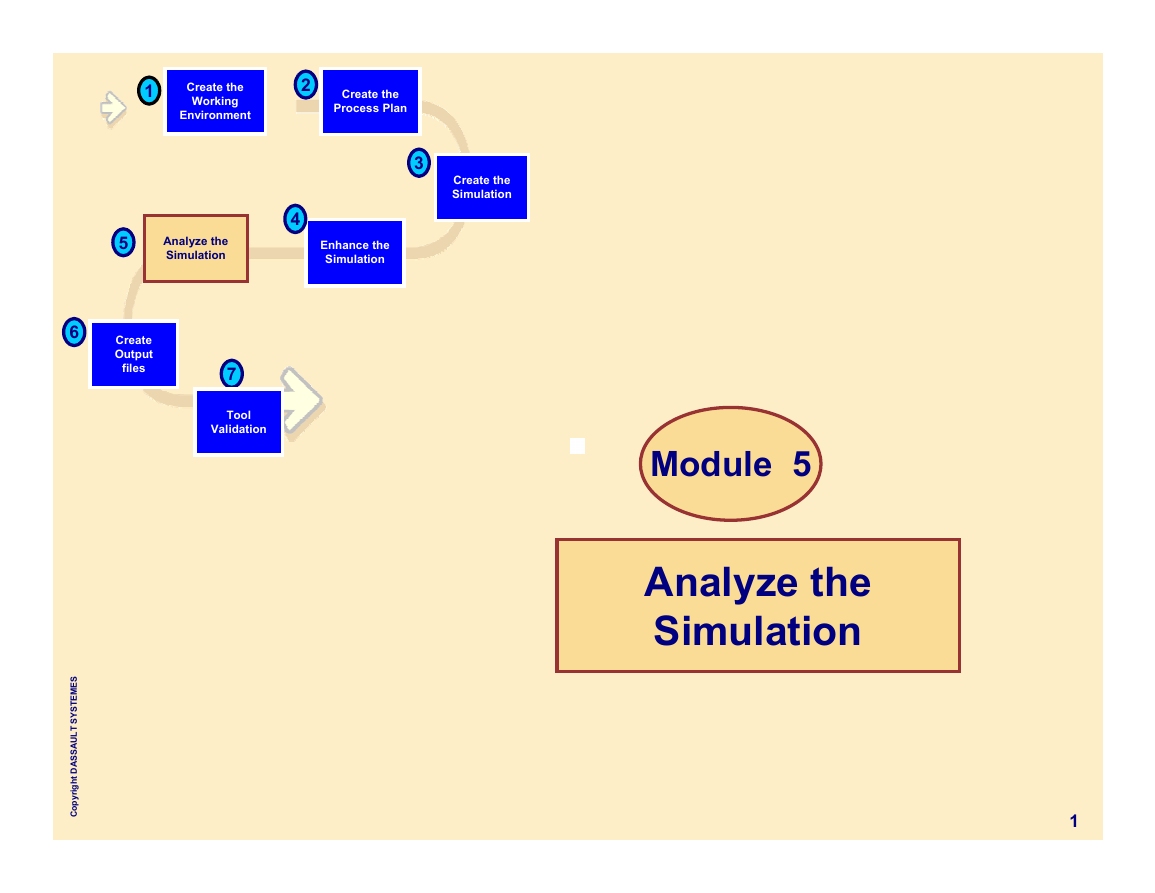
1
Create the
Working
Environment
2
Create the
Process Plan
3
Create the
Simulation
5
Analyze the
Simulation
4
Enhance the
Simulation
6
Create
Output
files
7
Tool
Validation
S
E
M
E
T
S
Y
S
T
L
U
A
S
S
A
D
t
h
g
i
r
y
p
o
C
Module 5
Analyze the
Simulation
1
�
5 Analyze the Simulation
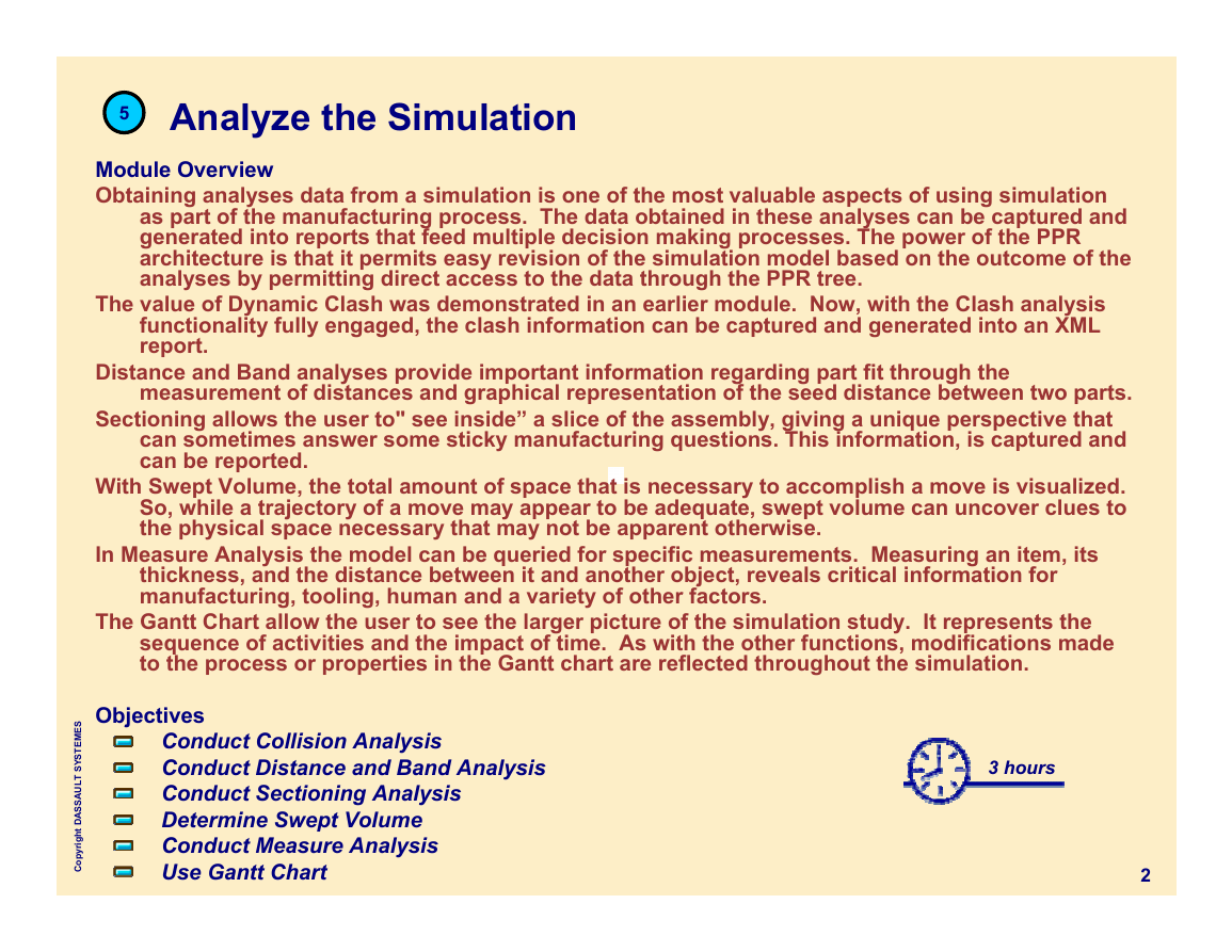
Module Overview
Obtaining analyses data from a simulation is one of the most valuable aspects of using simulation
as part of the manufacturing process. The data obtained in these analyses can be captured and
generated into reports that feed multiple decision making processes. The power of the PPR
architecture is that it permits easy revision of the simulation model based on the outcome of the
analyses by permitting direct access to the data through the PPR tree.
The value of Dynamic Clash was demonstrated in an earlier module. Now, with the Clash analysis
functionality fully engaged, the clash information can be captured and generated into an XML
report.
Distance and Band analyses provide important information regarding part fit through the
measurement of distances and graphical representation of the seed distance between two parts.
Sectioning allows the user to" see inside” a slice of the assembly, giving a unique perspective that
can sometimes answer some sticky manufacturing questions. This information, is captured and
can be reported.
With Swept Volume, the total amount of space that is necessary to accomplish a move is visualized.
So, while a trajectory of a move may appear to be adequate, swept volume can uncover clues to
the physical space necessary that may not be apparent otherwise.
In Measure Analysis the model can be queried for specific measurements. Measuring an item, its
thickness, and the distance between it and another object, reveals critical information for
manufacturing, tooling, human and a variety of other factors.
The Gantt Chart allow the user to see the larger picture of the simulation study. It represents the
sequence of activities and the impact of time. As with the other functions, modifications made
to the process or properties in the Gantt chart are reflected throughout the simulation.
Objectives
Conduct Collision Analysis
Conduct Distance and Band Analysis
Conduct Sectioning Analysis
Determine Swept Volume
Conduct Measure Analysis
Use Gantt Chart
S
E
M
E
T
S
Y
S
T
L
U
A
S
S
A
D
t
h
g
i
r
y
p
o
C
3 hours
2
�
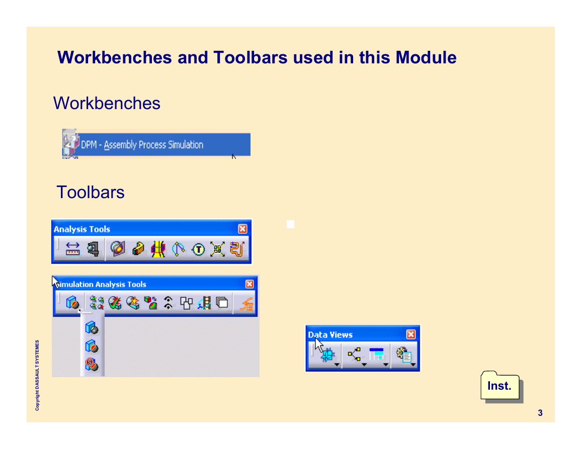
Workbenches and Toolbars used in this Module
Workbenches
Toolbars
S
E
M
E
T
S
Y
S
T
L
U
A
S
S
A
D
t
h
g
i
r
y
p
o
C
Inst.
Inst.
3
�
5
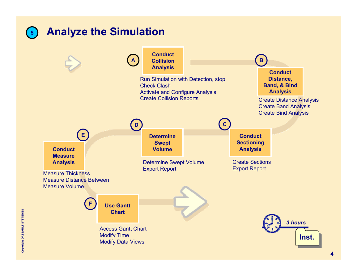
Analyze the Simulation
A
Conduct
Collision
Analysis
Run Simulation with Detection, stop
Check Clash
Activate and Configure Analysis
Create Collision Reports
B
Conduct
Distance,
Band, & Bind
Analysis
Create Distance Analysis
Create Band Analysis
Create Bind Analysis
E
Conduct
Measure
Analysis
Measure Thickness
Measure Distance Between
Measure Volume
D
C
Determine
Swept
Volume
Determine Swept Volume
Export Report
Conduct
Sectioning
Analysis
Create Sections
Export Report
S
E
M
E
T
S
Y
S
T
L
U
A
S
S
A
D
t
h
g
i
r
y
p
o
C
F
Use Gantt
Chart
Access Gantt Chart
Modify Time
Modify Data Views
3 hours
Inst.
Inst.
4
�
Conduct
Collision
Analysis
A
Run Simulation with Detection
Check Clash
Activate and Configure Analysis
Create Collision Reports
S
E
M
E
T
S
Y
S
T
L
U
A
S
S
A
D
t
h
g
i
r
y
p
o
C
Inst.
Inst.
5
�
5
Analyze the Simulation
About Collision Analysis
Conduct
Collision
Analysis
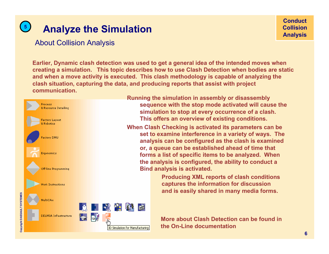
Earlier, Dynamic clash detection was used to get a general idea of the intended moves when
creating a simulation. This topic describes how to use Clash Detection when bodies are static
and when a move activity is executed. This clash methodology is capable of analyzing the
clash situation, capturing the data, and producing reports that assist with project
communication.
Running the simulation in assembly or disassembly
sequence with the stop mode activated will cause the
simulation to stop at every occurrence of a clash.
This offers an overview of existing conditions.
When Clash Checking is activated its parameters can be
set to examine interference in a variety of ways. The
analysis can be configured as the clash is examined
or, a queue can be established ahead of time that
forms a list of specific items to be analyzed. When
the analysis is configured, the ability to conduct a
Bind analysis is activated.
Producing XML reports of clash conditions
captures the information for discussion
and is easily shared in many media forms.
More about Clash Detection can be found in
the On-Line documentation
6
S
E
M
E
T
S
Y
S
T
L
U
A
S
S
A
D
t
h
g
i
r
y
p
o
C
�
5
Analyze the Simulation
Run the Simulation in Stop mode - Procedure
Conduct
Collision
Analysis
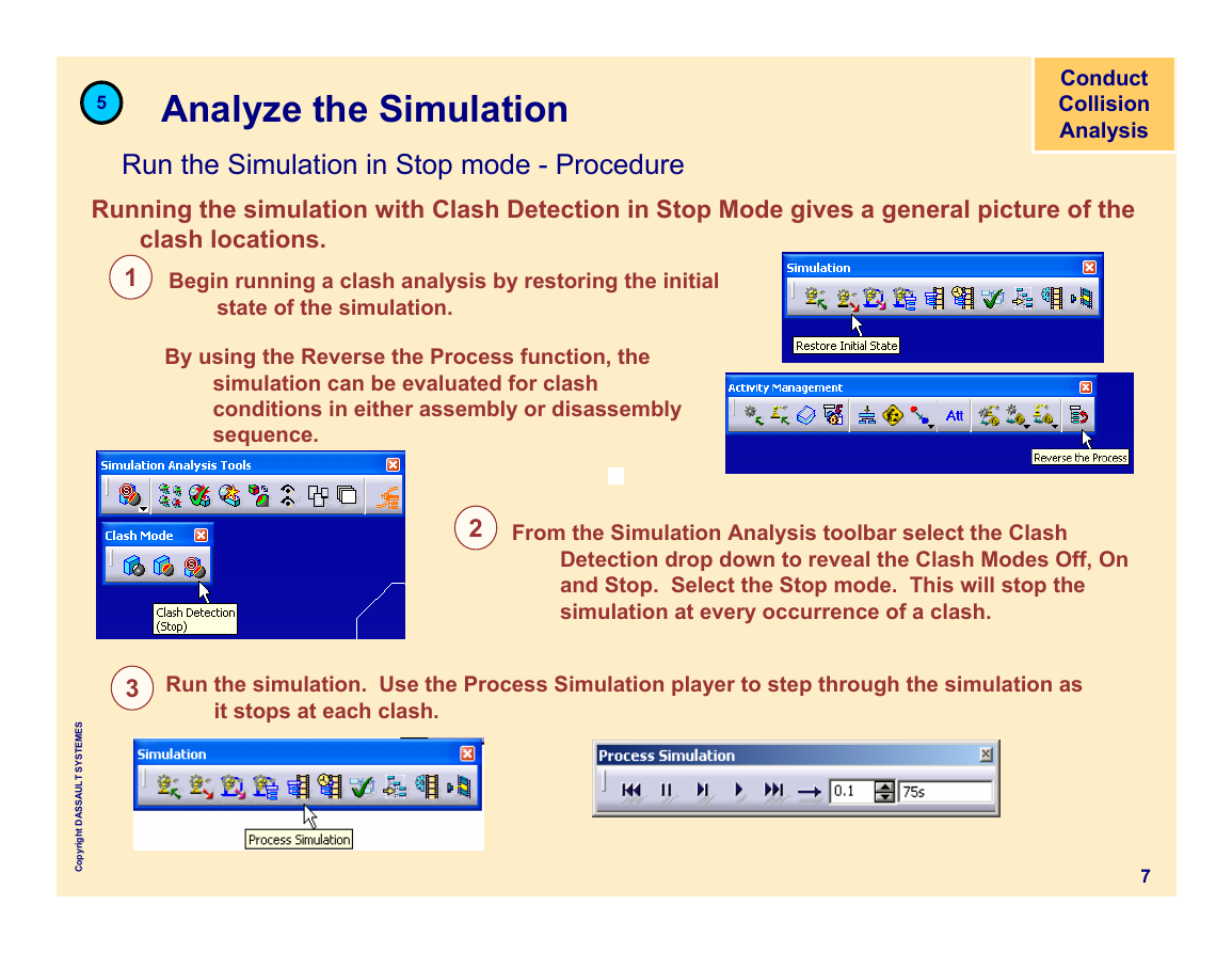
Running the simulation with Clash Detection in Stop Mode gives a general picture of the
clash locations.
1 Begin running a clash analysis by restoring the initial
state of the simulation.
By using the Reverse the Process function, the
simulation can be evaluated for clash
conditions in either assembly or disassembly
sequence.
2
From the Simulation Analysis toolbar select the Clash
Detection drop down to reveal the Clash Modes Off, On
and Stop. Select the Stop mode. This will stop the
simulation at every occurrence of a clash.
3 Run the simulation. Use the Process Simulation player to step through the simulation as
it stops at each clash.
7
S
E
M
E
T
S
Y
S
T
L
U
A
S
S
A
D
t
h
g
i
r
y
p
o
C
�
5
Analyze the Simulation
Clash Checking - Procedure
Conduct
Collision
Analysis
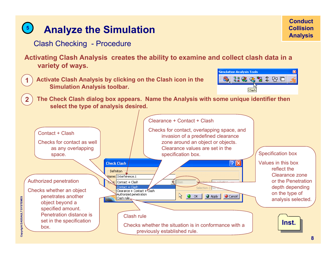
Activating Clash Analysis creates the ability to examine and collect clash data in a
variety of ways.
1 Activate Clash Analysis by clicking on the Clash icon in the
Simulation Analysis toolbar.
2
The Check Clash dialog box appears. Name the Analysis with some unique identifier then
select the type of analysis desired.
Contact + Clash
Checks for contact as well
as any overlapping
space.
Authorized penetration
Checks whether an object
penetrates another
object beyond a
specified amount.
Penetration distance is
set in the specification
box.
S
E
M
E
T
S
Y
S
T
L
U
A
S
S
A
D
t
h
g
i
r
y
p
o
C
Clearance + Contact + Clash
Checks for contact, overlapping space, and
invasion of a predefined clearance
zone around an object or objects.
Clearance values are set in the
specification box.
Clash rule
Checks whether the situation is in conformance with a
previously established rule.
Specification box
Values in this box
reflect the
Clearance zone
or the Penetration
depth depending
on the type of
analysis selected.
Inst.
Inst.
8
�


 2023年江西萍乡中考道德与法治真题及答案.doc
 2012年重庆南川中考生物真题及答案.doc
 2013年江西师范大学地理学综合及文艺理论基础考研真题.doc
 2020年四川甘孜小升初语文真题及答案I卷.doc
 2020年注册岩土工程师专业基础考试真题及答案.doc
 2023-2024学年福建省厦门市九年级上学期数学月考试题及答案.doc
 2021-2022学年辽宁省沈阳市大东区九年级上学期语文期末试题及答案.doc
 2022-2023学年北京东城区初三第一学期物理期末试卷及答案.doc
 2018上半年江西教师资格初中地理学科知识与教学能力真题及答案.doc
 2012年河北国家公务员申论考试真题及答案-省级.doc
 2020-2021学年江苏省扬州市江都区邵樊片九年级上学期数学第一次质量检测试题及答案.doc
 2022下半年黑龙江教师资格证中学综合素质真题及答案.doc