logo资料库

IEI威强掌上无线-EP-165E-N270说明书.pdf

第1页 / 共139页
第2页 / 共139页
第3页 / 共139页
第4页 / 共139页
第5页 / 共139页
第6页 / 共139页
第7页 / 共139页
第8页 / 共139页
资料共139页,剩余部分请下载后查看
1 Introduction
1.1 Overview
1.2 Features
1.3 External Overview
1.3.1 Front Panel
1.3.2 Rear Panel
1.3.3 I/O Interface Rear Access Panel
1.3.4 Top Panel
1.3.5 Bottom Panel I/O Interface Connectors
1.3.6 Right Side Panel
1.4 Specifications
1.4.1 System Specifications
1.5 Dimensions
2 Installation
2.1 Unpack the Panel PC
2.2 Packing List
2.3 Back cover removal
2.4 HDD Installation
2.5 CF Card Installation
2.6 Mini PCI card Installation
2.7 Jumper Settings
2.7.1 Access the Jumpers
2.7.2 Preconfigured Jumpers
2.7.3 Cash Drawer Voltage Select
2.7.4 CompactFlash® Card Setup
2.7.5 Clear CMOS Jumper
2.7.6 COM2, COM3 and COM5 Pin 9 Select
2.7.7 COM4 and COM6 Pin 9 Select
2.8 Installing the System
2.9 Mounting the System
2.9.1 Stand Installation
2.9.2 Wall Mounting (Optional)
2.10 I/O Interface Connectors
2.10.1 LAN Connection Cable
2.10.2 USB Device Cable
2.10.3 Parallel Device Connection
2.10.4 PoweredUSB Cable
2.10.5 PS/2 Keyboard and Mouse Connection
2.10.6 RJ-11 Connectors for Cash Drawer Power
2.10.7 Serial Device Connection
2.10.8 VGA Monitor Connection
2.11 System Power
2.11.1 Power Mode
2.11.1.1 AT Power Mode
2.11.1.2 ATX Power Mode
2.11.2 Power Supply
2.11.3 Power Connectors
2.11.3.1 Power Input Connector
2.11.3.2 Power Output Connector
2.12 Driver Installation
3 BIOS Setup
3.1 Introduction
3.1.1 Starting Setup
3.1.2 Using Setup
3.1.3 Getting Help
3.1.4 Unable to Reboot After Configuration Changes
3.1.5 BIOS Menu Bar
3.2 Main
3.3 Advanced
3.3.1 CPU Configuration
3.3.2 IDE Configuration
3.3.2.1 IDE Master, IDE Slave
3.3.3 Super IO Configuration
3.3.4 Hardware Health Configuration
3.3.5 Power Configuration
3.3.6 APM Configuration
3.3.7 Remote Access Configuration
3.3.8 USB Configuration
3.3.8.1 USB Mass Storage Device Configuration
3.4 PCI/PnP
3.5 Boot
3.5.1 Boot Settings Configuration
3.5.2 Boot Device Priority
3.5.3 Hard Disk Drives
3.5.4 Removable Drives
3.5.5 CD/DVD Drives
3.6 Security
3.7 Chipset
3.7.1 Northbridge Configuration
3.7.2 Southbridge Configuration
3.8 Exit
4 System Maintenance
4.1 System Maintenance Introduction
4.2 Motherboard Replacement
4.3 Cover Removal
4.4 Memory Module Replacement
4.5 Hard Drive and CompactFlash® Replacement
5 iSMM
5.1 iSMM Introduction
5.2 iSMM Installation
5.3 Voltage Page
5.3.1 Refresh Time Setting
5.3.2 High Limit Value and Low Limit Value Setting
5.4 Fan Page
5.4.1 Refresh Time Setting
5.4.2 High Limit Value and Low Limit Value Setting
5.4.3 Smart Fan Setting
5.4.3.1 On/Off Mode
5.4.3.2 PWM Mode
5.4.3.3 Automatic Mode
5.5 Temperature Page
5.5.1 Refresh Time Setting
5.5.2 High Limit Value and Low Limit Value Setting
5.6 Cash Drawer Page
5.7 Watchdog Timer Page
5.8 DIO Page
5.8.1 GPO Information Setting
5.9 Load/Save Page

EP-165E-N270 series Enrich POS IEI Technology Corp. MODEL: EP-165E-N270 series Fanless Intel® Atom™ N270 CPU Enrich POS System with VGA for Second Screen, LAN, 802.11a/b/g, PoweredUSB, Powered 5 V/12 V Serial Ports, and AT/ATX Power Support, RoHS Compliant, IP 64 User Manual Rev. 1.00 – 9 September, 2009 Page i
EP-165E-N270 series Enrich POS Revision Date Version Changes 9 September, 2009 1.00 Initial release Page ii
EP-165E-N270 series Enrich POS Copyright COPYRIGHT NOTICE The information in this document is subject to change without prior notice in order to improve reliability, design and function and does not represent a commitment on the part of the manufacturer. In no event will the manufacturer be liable for direct, indirect, special, incidental, or consequential damages arising out of the use or inability to use the product or documentation, even if advised of the possibility of such damages. This document contains proprietary information protected by copyright. All rights are reserved. No part of this manual may be reproduced by any mechanical, electronic, or other means in any form without prior written permission of the manufacturer. TRADEMARKS All registered trademarks and product names mentioned herein are used for identification purposes only and may be trademarks and/or registered trademarks of their respective owners. Page iii
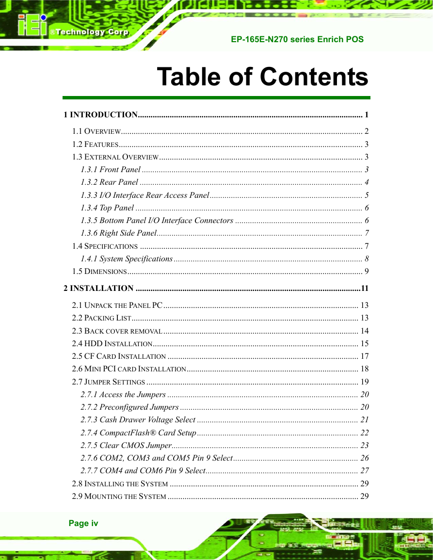
EP-165E-N270 series Enrich POS Table of Contents 1 INTRODUCTION.......................................................................................................... 1 1.1 OVERVIEW.................................................................................................................. 2 1.2 FEATURES................................................................................................................... 3 1.3 EXTERNAL OVERVIEW................................................................................................ 3 1.3.1 Front Panel ........................................................................................................ 3 1.3.2 Rear Panel ......................................................................................................... 4 1.3.3 I/O Interface Rear Access Panel........................................................................ 5 1.3.4 Top Panel ........................................................................................................... 6 1.3.5 Bottom Panel I/O Interface Connectors ............................................................ 6 1.3.6 Right Side Panel................................................................................................. 7 1.4 SPECIFICATIONS ......................................................................................................... 7 1.4.1 System Specifications......................................................................................... 8 1.5 DIMENSIONS............................................................................................................... 9 2 INSTALLATION ..........................................................................................................11 2.1 UNPACK THE PANEL PC............................................................................................ 13 2.2 PACKING LIST........................................................................................................... 13 2.3 BACK COVER REMOVAL............................................................................................ 14 2.4 HDD INSTALLATION................................................................................................. 15 2.5 CF CARD INSTALLATION .......................................................................................... 17 2.6 MINI PCI CARD INSTALLATION................................................................................. 18 2.7 JUMPER SETTINGS .................................................................................................... 19 2.7.1 Access the Jumpers .......................................................................................... 20 2.7.2 Preconfigured Jumpers .................................................................................... 20 2.7.3 Cash Drawer Voltage Select ............................................................................ 21 2.7.4 CompactFlash® Card Setup............................................................................ 22 2.7.5 Clear CMOS Jumper........................................................................................ 23 2.7.6 COM2, COM3 and COM5 Pin 9 Select........................................................... 26 2.7.7 COM4 and COM6 Pin 9 Select........................................................................ 27 2.8 INSTALLING THE SYSTEM ......................................................................................... 29 2.9 MOUNTING THE SYSTEM .......................................................................................... 29 Page iv
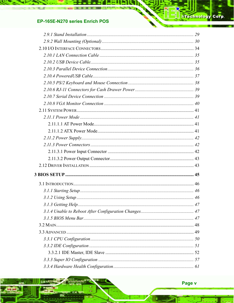
EP-165E-N270 series Enrich POS 2.9.1 Stand Installation ............................................................................................. 29 2.9.2 Wall Mounting (Optional)................................................................................ 30 2.10 I/O INTERFACE CONNECTORS................................................................................. 34 2.10.1 LAN Connection Cable .................................................................................. 35 2.10.2 USB Device Cable.......................................................................................... 35 2.10.3 Parallel Device Connection........................................................................... 36 2.10.4 PoweredUSB Cable........................................................................................ 37 2.10.5 PS/2 Keyboard and Mouse Connection ......................................................... 38 2.10.6 RJ-11 Connectors for Cash Drawer Power ................................................... 39 2.10.7 Serial Device Connection .............................................................................. 39 2.10.8 VGA Monitor Connection .............................................................................. 40 2.11 SYSTEM POWER...................................................................................................... 41 2.11.1 Power Mode ................................................................................................... 41 2.11.1.1 AT Power Mode....................................................................................... 41 2.11.1.2 ATX Power Mode.................................................................................... 41 2.11.2 Power Supply.................................................................................................. 42 2.11.3 Power Connectors.......................................................................................... 42 2.11.3.1 Power Input Connector ........................................................................... 42 2.11.3.2 Power Output Connector......................................................................... 43 2.12 DRIVER INSTALLATION........................................................................................... 43 3 BIOS SETUP ................................................................................................................ 45 3.1 INTRODUCTION......................................................................................................... 46 3.1.1 Starting Setup................................................................................................... 46 3.1.2 Using Setup ...................................................................................................... 46 3.1.3 Getting Help..................................................................................................... 47 3.1.4 Unable to Reboot After Configuration Changes.............................................. 47 3.1.5 BIOS Menu Bar................................................................................................ 47 3.2 MAIN........................................................................................................................ 48 3.3 ADVANCED............................................................................................................... 49 3.3.1 CPU Configuration.......................................................................................... 50 3.3.2 IDE Configuration ........................................................................................... 51 3.3.2.1 IDE Master, IDE Slave ............................................................................. 52 3.3.3 Super IO Configuration ................................................................................... 57 3.3.4 Hardware Health Configuration...................................................................... 61 Page v
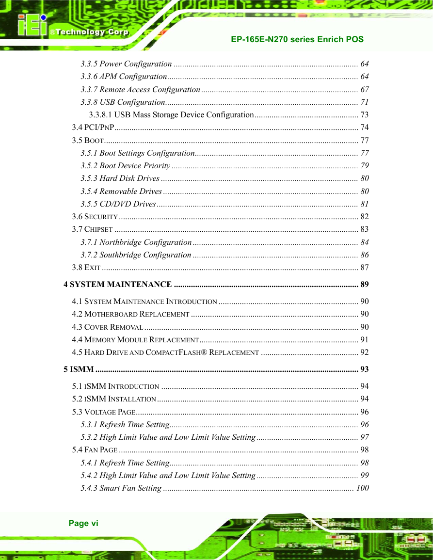
EP-165E-N270 series Enrich POS 3.3.5 Power Configuration ....................................................................................... 64 3.3.6 APM Configuration.......................................................................................... 64 3.3.7 Remote Access Configuration .......................................................................... 67 3.3.8 USB Configuration........................................................................................... 71 3.3.8.1 USB Mass Storage Device Configuration................................................. 73 3.4 PCI/PNP................................................................................................................... 74 3.5 BOOT........................................................................................................................ 77 3.5.1 Boot Settings Configuration............................................................................. 77 3.5.2 Boot Device Priority ........................................................................................ 79 3.5.3 Hard Disk Drives ............................................................................................. 80 3.5.4 Removable Drives ............................................................................................ 80 3.5.5 CD/DVD Drives............................................................................................... 81 3.6 SECURITY................................................................................................................. 82 3.7 CHIPSET ................................................................................................................... 83 3.7.1 Northbridge Configuration .............................................................................. 84 3.7.2 Southbridge Configuration .............................................................................. 86 3.8 EXIT ......................................................................................................................... 87 4 SYSTEM MAINTENANCE ....................................................................................... 89 4.1 SYSTEM MAINTENANCE INTRODUCTION .................................................................. 90 4.2 MOTHERBOARD REPLACEMENT ............................................................................... 90 4.3 COVER REMOVAL..................................................................................................... 90 4.4 MEMORY MODULE REPLACEMENT........................................................................... 91 4.5 HARD DRIVE AND COMPACTFLASH® REPLACEMENT .............................................. 92 5 ISMM ............................................................................................................................ 93 5.1 ISMM INTRODUCTION ............................................................................................. 94 5.2 ISMM INSTALLATION............................................................................................... 94 5.3 VOLTAGE PAGE......................................................................................................... 96 5.3.1 Refresh Time Setting......................................................................................... 96 5.3.2 High Limit Value and Low Limit Value Setting................................................ 97 5.4 FAN PAGE ................................................................................................................. 98 5.4.1 Refresh Time Setting......................................................................................... 98 5.4.2 High Limit Value and Low Limit Value Setting................................................ 99 5.4.3 Smart Fan Setting .......................................................................................... 100 Page vi
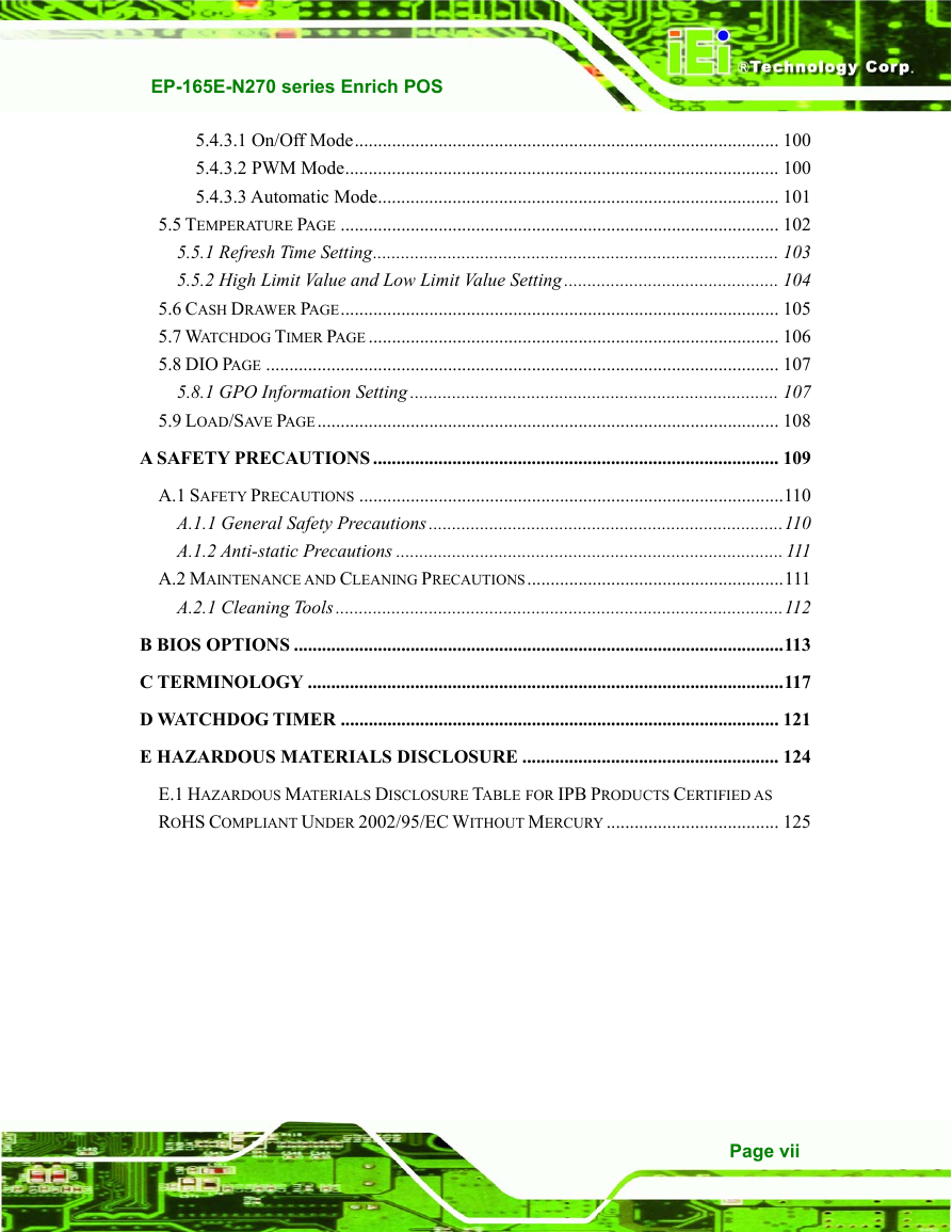
EP-165E-N270 series Enrich POS 5.4.3.1 On/Off Mode........................................................................................... 100 5.4.3.2 PWM Mode............................................................................................. 100 5.4.3.3 Automatic Mode...................................................................................... 101 5.5 TEMPERATURE PAGE .............................................................................................. 102 5.5.1 Refresh Time Setting....................................................................................... 103 5.5.2 High Limit Value and Low Limit Value Setting.............................................. 104 5.6 CASH DRAWER PAGE.............................................................................................. 105 5.7 WATCHDOG TIMER PAGE ........................................................................................ 106 5.8 DIO PAGE .............................................................................................................. 107 5.8.1 GPO Information Setting ............................................................................... 107 5.9 LOAD/SAVE PAGE................................................................................................... 108 A SAFETY PRECAUTIONS ....................................................................................... 109 A.1 SAFETY PRECAUTIONS ...........................................................................................110 A.1.1 General Safety Precautions............................................................................110 A.1.2 Anti-static Precautions ...................................................................................111 A.2 MAINTENANCE AND CLEANING PRECAUTIONS.......................................................111 A.2.1 Cleaning Tools................................................................................................112 B BIOS OPTIONS .........................................................................................................113 C TERMINOLOGY ......................................................................................................117 D WATCHDOG TIMER .............................................................................................. 121 E HAZARDOUS MATERIALS DISCLOSURE ....................................................... 124 E.1 HAZARDOUS MATERIALS DISCLOSURE TABLE FOR IPB PRODUCTS CERTIFIED AS ROHS COMPLIANT UNDER 2002/95/EC WITHOUT MERCURY ..................................... 125 Page vii
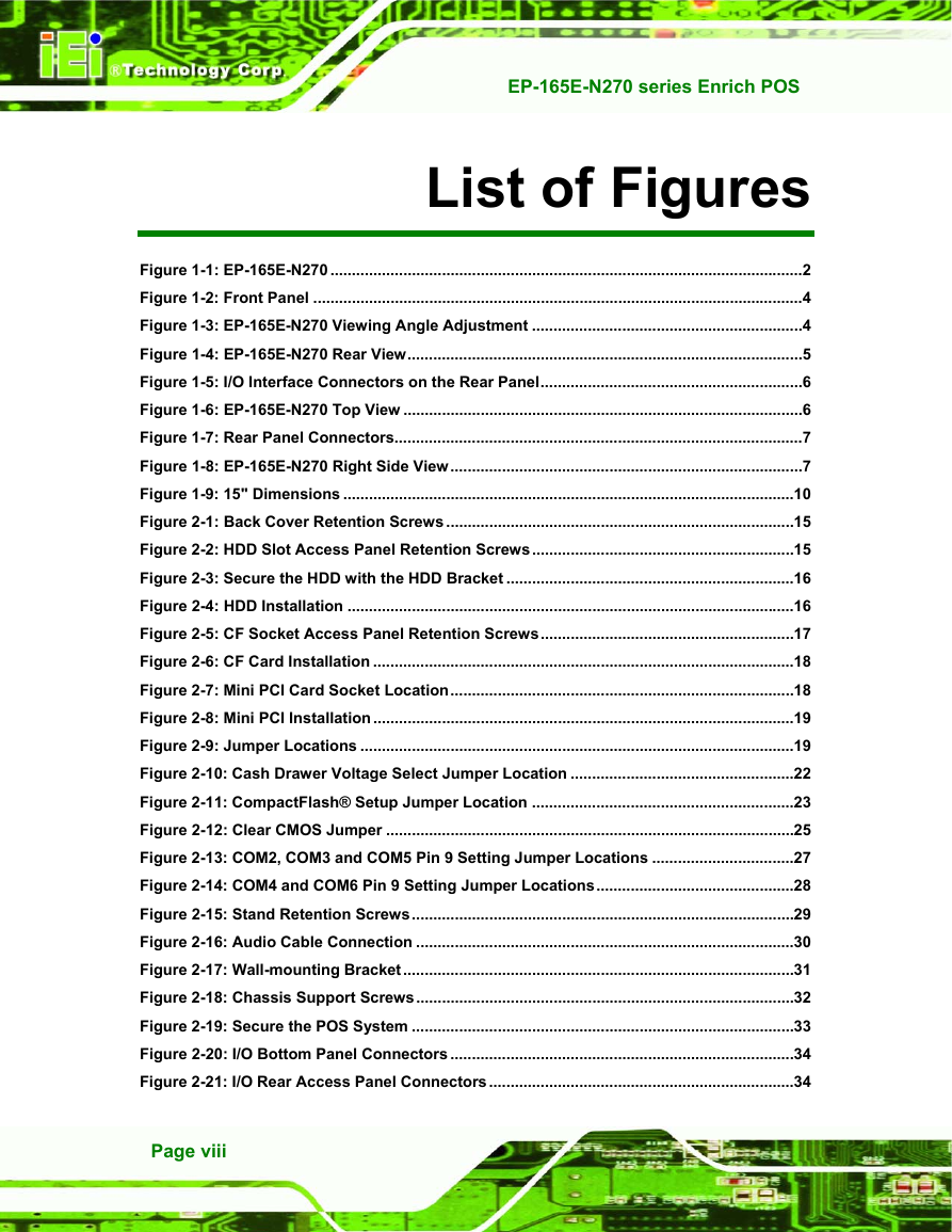
EP-165E-N270 series Enrich POS List of Figures Figure 1-1: EP-165E-N270 ..............................................................................................................2 Figure 1-2: Front Panel ..................................................................................................................4 Figure 1-3: EP-165E-N270 Viewing Angle Adjustment ...............................................................4 Figure 1-4: EP-165E-N270 Rear View............................................................................................5 Figure 1-5: I/O Interface Connectors on the Rear Panel.............................................................6 Figure 1-6: EP-165E-N270 Top View .............................................................................................6 Figure 1-7: Rear Panel Connectors...............................................................................................7 Figure 1-8: EP-165E-N270 Right Side View..................................................................................7 Figure 1-9: 15" Dimensions .........................................................................................................10 Figure 2-1: Back Cover Retention Screws .................................................................................15 Figure 2-2: HDD Slot Access Panel Retention Screws.............................................................15 Figure 2-3: Secure the HDD with the HDD Bracket ...................................................................16 Figure 2-4: HDD Installation ........................................................................................................16 Figure 2-5: CF Socket Access Panel Retention Screws...........................................................17 Figure 2-6: CF Card Installation ..................................................................................................18 Figure 2-7: Mini PCI Card Socket Location................................................................................18 Figure 2-8: Mini PCI Installation..................................................................................................19 Figure 2-9: Jumper Locations .....................................................................................................19 Figure 2-10: Cash Drawer Voltage Select Jumper Location ....................................................22 Figure 2-11: CompactFlash® Setup Jumper Location .............................................................23 Figure 2-12: Clear CMOS Jumper ...............................................................................................25 Figure 2-13: COM2, COM3 and COM5 Pin 9 Setting Jumper Locations .................................27 Figure 2-14: COM4 and COM6 Pin 9 Setting Jumper Locations..............................................28 Figure 2-15: Stand Retention Screws.........................................................................................29 Figure 2-16: Audio Cable Connection ........................................................................................30 Figure 2-17: Wall-mounting Bracket...........................................................................................31 Figure 2-18: Chassis Support Screws........................................................................................32 Figure 2-19: Secure the POS System .........................................................................................33 Figure 2-20: I/O Bottom Panel Connectors ................................................................................34 Figure 2-21: I/O Rear Access Panel Connectors.......................................................................34 Page viii
分享到:
收藏