Bookcase
Table of Contents
List of Tables
List of Figures
Chapter 1 About Common Resources
Chapter 2 Design Rule Checking
DFTAdvisor Rules Checking
Troubleshooting Rules Violations
Setting the Handling of Rules
Turning on ATPG Analysis
Setting the Level of Gate Data
Setting the Gate Information Type
Reporting Gate Data
Reporting on a Specific Gate
Reporting on All Gates of a Specified Type
Reporting a Histogram of All Gate Types
Reporting on a Path Between Two Gates
Reporting on the First Input of a Gate
Reporting on the First Fanout of a Gate
Flattening Rule Violations
The Design Rules
RAM Rules (A Rules)
A1
A2
A3
A4
A5
A6
A7
A8
A9
A10
A11
A12
A13
BIST Rules (B Rules)
B1
B2
B3
B4
B5
B6
B7
B8
B9
B10
B11
B12
B13
B14
B15
B16
Clock Rules (C Rules)
Clock Terminology
Clock Signals
Clock Cones and Effect Cones
The ATPG Analysis Option
C1
C2
C3
C4
C5
C6
C7
C8
C9
C10
C11
C12
C13
C14
C15
C16
C17
Scan Cell Data Rules (D Rules)
D1
D2
D3
D4
D5
D6
D7
D8
D9
D10
D11
Extra Rules (E Rules)
E1
E2
E3
E4
E5
E6
E7
E8
E9
E10
E11
E12
E13
E14
Flattening Rules (F Rules)
FN1
FN2
FN3
FN4
FN5
FN6
FN7
FN8
FN9
FP1
FP2
FP3
FP4
FP5
FP6
FP7
FP8
FP9
FP10
FP11
FP12
FP13
FG1
FG2
FG3
FG4
FG5
FG6
FG7
FG8
General Rules (G Rules)
G1
G2
G3
G4
G5
G6
G7
G8
G9
G10
G11
G12
EDT Rules (K Rules)
K1
K2
K3
K4
K5
K6
K7
K8
K9
K10
K11
K12
K13
K14
K15
K16
K17
K18
K19
K20
K21
K22
K23
K24
K25
Procedure Rules (P Rules)
P1
P2
P3
P4
P5
P6
P7
P8
P9
P10
P11
P12
P13
P14
P15
P16
P17
P18
P19
P20
P21
P22
P23
P24
P25
P26
P27
P28
P29
P30
P31
P32
P33
P34
P35
P36
P37
P38
P39
P40
P41
P42
P43
P44
P45
P46
P47
P48
P49
P50
P51
P52
P53
P54
P55
P56
P57
P58
P59
P62
P63
P64
P65
P70
Scanability Rules (S Rules)
S1
S2
S3
S4
Scan Chain Trace Rules (T Rules)
T1
T2
T3
T4
T5
T6
T8
T9
T10
T11
T12
T13
T14
T15
T16
T17
T18
T19
T20
T21
T22
T23
T24
T25
T26
Timing Rules (W Rules)
W1
W2
W3
W4
W5
W6
W7
W8
W9
W10
W11
W12
W13
W14
W15
W16
W17
W18
W19
W20
W21
W22
W23
W24
W25
W26
W27
W28
W29
W30
W31
W32
W33
W34
W35
W36
W37
W38
Other DRC Messages
Transparent Capture Handling Analysis
Oscillation Limitation
RAM Summary Results and Test Capability
Chapter 3 Getting Started with DFTVisualizer
Opening DFTVisualizer
Understanding the DFTVisualizer Windows
Performing Basic Tasks
Saving and Restoring Displays
Searching for an Instance, Net, or Pin
Undocking and Docking Windows
Resizing Windows
Understanding Popup Menus
Copying an Object Name from a Popup Menu to the System Clipboard
Adding Instances to a Display Window
Selecting Objects
Cross-Selecting Objects
Selecting Objects in the Debug or Design Window
Unselecting Objects
Copying Instances Between Windows
Tracing Signal Paths on a Schematic
Understanding Trace Options
Compacting Buffers and Inverters in Traced Circuitry
Tracing a Specific Signal Value to the Source
Tracing Signal Paths in the Design Window
Tracing Up and Down the Design Hierarchy
Bundling Nets
Annotating Schematic Data in the Debug Window
Displaying Multiple Data Sets
Analyzing a DRC Violation
Step 1 - Run an Analysis of the Violation
Running the Analysis
Step 2 - Find the Source of Problem Signals
Step 3 - Apply a Remedy and Rerun DRC
Assessing Test Coverage in the Browser
Analyzing a Fault and Displaying its Location
Executing Report Test Stimulus
Getting Oriented in a Large Design
Setting DFTVisualizer Preferences
Saving/Loading Session Preferences
Understanding the DFTVisualizer Preferences Dialog Box
Global Preferences Dialog Box
Colors Preferences Dialog Box
Debug Window Preferences Dialog Box
Design Window Preferences Dialog Box
Browser Window Preferences Dialog Box
Data Window Preferences Dialog Box
Text Editor Window Preferences Dialog Box
Objects Added to DFTVisualizer Windows
Task Manager Window
Browser Window
Data Window
Debug Window
Design Window
Format Guide Window
Global Search Window
Library Browser Window
Signals Window
Text Editor Window
Transcript Window
Wave Window
DFTVisualizer Command Quick Reference
Chapter 4 Design Library
Defining Scan Information
Defining a Scan Cell Model
Example Scan Definitions
Basic Example
MUX-Scan Cell
Clocked-Scan Cell
LSSD Cell
Complex Scan Model
Defining a Model
Model_name
List_of_pins
Interface Pins and Internal Nodes
Input Statement
Intern Statement
Inout Statement
Output Statement
Cell_type
Attributes
Input Attributes
Intern Attributes
Inout and Output Attributes
Primitive and Attribute Examples
Internal Faults
Support of Arrays Within Library Models
Defining Macros
Using Model Aliases
Reading Multiple Libraries
Verilog Primitives
Supported Primitives
AND Gate
NAND Gate
OR Gate
NOR Gate
Inverter
Buffer
Buffer With High Impedance Output
XOR Gate
XNOR Gate
Tri-State Buffer with Active Low Control
Inverted Tri-State Buffer with Active Low Control
Tri-State Buffer with Active High Control
Inverted Tri-State Buffer with Active High Control
Multiplexer
D Flip-Flop
D Latch
One Time Unit Delay Element (FlexTest Only)
Feedback Inverter
Wire Element
Pull-Up or Pull-Down Device
Power Signal
Ground Signal
Unknown Signal
High Impedance Signal
Undefined
Unidirectional NMOS Transistor
Unidirectional PMOS Transistor
Unidirectional Resistive NMOS Transistor
Unidirectional Resistive PMOS Transistor
Unidirectional Feedback NMOS Transistor
Unidirectional Feedback PMOS Transistor
Unidirectional CMOS1 Transistor
Unidirectional CMOS2 Transistor
Unidirectional Resistive CMOS1 Transistor
Unidirectional Resistive CMOS2 Transistor
Unidirectional Feedback CMOS1 Transistor
Unidirectional Feedback CMOS2 Transistor
Pulse Generators with User Defined Timing
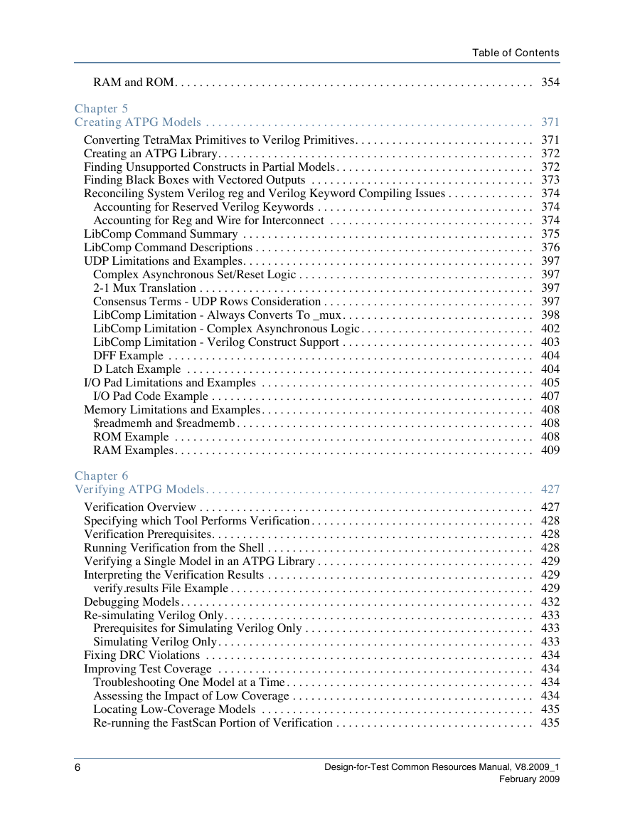
RAM and ROM
RAM and ROM Basics
RAM/ROM Library Primitives
ROM Library Primitive
Basic RAM Library Primitive
Comprehensive RAM Primitive
Attributes of RAM/ROM Primitives
Initialization Files for RAM and ROM
ROM and RAM Port Behavior
Read Port Behavior for _rom and _ram
Read Port Behavior for _cram
Set and Reset Lines for _ram and _cram
Write Port Behavior for _ram
Write Port Behavior for _cram
Read_Write Port Behavior for _cram
DRC for RAMs
ROM Limitations
RAM Limitations
Chapter 5 Creating ATPG Models
Converting TetraMax Primitives to Verilog Primitives
Creating an ATPG Library
Finding Unsupported Constructs in Partial Models
Finding Black Boxes with Vectored Outputs
Reconciling System Verilog reg and Verilog Keyword Compiling Issues
Accounting for Reserved Verilog Keywords
Accounting for Reg and Wire for Interconnect
LibComp Command Summary
LibComp Command Descriptions
Add Model
Delete Model
Dofile
Exit
Help
Load Library
Report Environment
Run
Set Asynchronous Control_Logic
Set Behavioral Processing
Set Dofile Abort
Set Excessive Pull_delay
Set Hold Check
Set System Mode
Set Verification
Set X_from_known Combinational_udp
System
Write Library
UDP Limitations and Examples
Complex Asynchronous Set/Reset Logic
2-1 Mux Translation
Consensus Terms - UDP Rows Consideration
UDP With Both Consensus Terms
LibComp Limitation - Always Converts To _mux
Default Solution - LibComp Outputs _mux
Manual Alternative Solution 1
Manual Alternative Solution 2
Partial Mux Examples - Missing Consensus Terms
Case 1 - Mux Missing 11 Consensus Term
Case 2 - Mux Missing 00 Consensus Term
Case 3 - Mux Missing Both Consensus Terms
Mux Example With Consensus Terms
LibComp Limitation - Complex Asynchronous Logic
Mux Scan DFF With Complex Asynchronous Logic
Example - Mux Scan DFF
Example - Mux Scan Cell With Asynchronous Gated Off By Scan Enable
LibComp Limitation - Verilog Construct Support
Behavioral Constructs
Structural Constructs
DFF Example
D Latch Example
I/O Pad Limitations and Examples
Strength Propagation
Pin Constraints Required for Verification
I/O Pad Code Example
Memory Limitations and Examples
$readmemh and $readmemb
ROM Example
RAM Examples
Single Posedge Ports With Separate Port Clocks
Single Level Ports With Write-Thru and Trisate Output Enable
Single Posedge Write Level Read Ports With Write-Thru
Single Posedge Ports With Separate Port Clocks
Single Level Ports With Separate Port Clocks
Single Posedge Ports With Write Enable
Single Level Ports With Single Read/Write Control and Bit- Blasted Wrapper
Single Level Ports With Read_Off 1 Output and Tristate Output Enable
Single Posedge Ports With Memory Bypass
Single Level Bidirectional Ports With Write-Thru and Output Enable
Single Posedge Ports With Port and Per-Bit Write Enables and Write_Thru
Dual Posedge Ports With Separate Clocks
Dual Posedge Write Level Read Ports With Separate Clocks
Dual Posedge Write Level Read Ports With Separate Clocks and Tristate Output Enable
Dual Level Ports With Separate Clocks and Write-Thru
Dual Posedge Bidirectional Ports With Read_Off 0 and Output Enable
Dual Posedge Separate Clocks Ports With Port and Per-Bit Write Enables
Chapter 6 Verifying ATPG Models
Verification Overview
Specifying which Tool Performs Verification
Verification Prerequisites
Running Verification from the Shell
Verifying a Single Model in an ATPG Library
Interpreting the Verification Results
verify.results File Example
Debugging Models
Re-simulating Verilog Only
Prerequisites for Simulating Verilog Only
Simulating Verilog Only
Fixing DRC Violations
Improving Test Coverage
Troubleshooting One Model at a Time
Assessing the Impact of Low Coverage
Locating Low-Coverage Models
Re-running the FastScan Portion of Verification
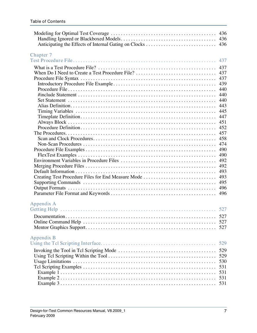
Modeling for Optimal Test Coverage
Handling Ignored or Blackboxed Models
Anticipating the Effects of Internal Gating on Clocks
Chapter 7 Test Procedure File
What is a Test Procedure File?
When Do I Need to Create a Test Procedure File?
Procedure File Syntax
Introductory Procedure File Example
Procedure File
#include Statement
Set Statement
Alias Definition
Timing Variables
Timeplate Definition
Always Block
Always Block Syntax
Always Block Example
Procedure Definition
The Procedures
Scan and Clock Procedures
Non-Scan Procedures
Non-Scan Procedure File
Viewing Optimized Named Capture Procedures (NCPs)
Rules for Creating and Editing a Default Capture Procedure
Rules for Creating and Editing Named Capture Procedures
Example Named Capture Procedure
Slow and Load Types
launch_capture_pair Statement
Example PLL Model and Named Capture Procedure
Example 1: Using test_end in a Procedure File
Example 2: Test_end Procedure with Timeplate
Sub_procedure Looping
Disabling Sub_procedure Looping
Sub_procedure Definition Format
Using the Sub_procedure in a Procedure
Procedure File Examples
FlexTest Examples
FlexTest Example 1
FlexTest Example 2
Environment Variables in Procedure Files
Merging Procedure Files
Default Information
Creating Test Procedure Files for End Measure Mode
Supporting Commands
Output Formats
Parameter File Format and Keywords
Appendix A Getting Help
Documentation
Online Command Help
Mentor Graphics Support
Invoking the Tool in Tcl Scripting Mode
Using Tcl Scripting Within the Tool
Usage Limitations
Tcl Scripting Examples
Example 1
Example 2
Example 3
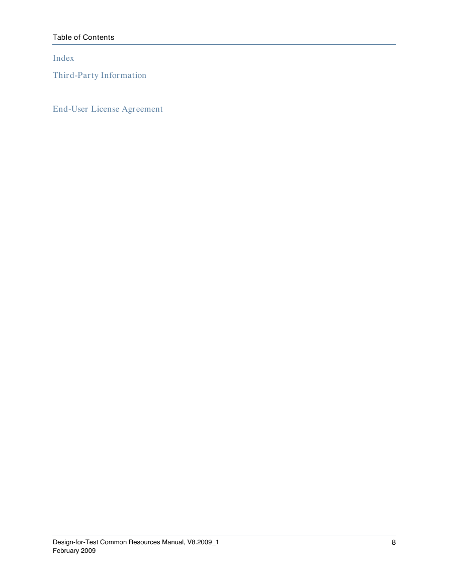
Index
Third-Party Information
End-User License Agreement
Documentation Feedback



 2023年江西萍乡中考道德与法治真题及答案.doc
 2012年重庆南川中考生物真题及答案.doc
 2013年江西师范大学地理学综合及文艺理论基础考研真题.doc
 2020年四川甘孜小升初语文真题及答案I卷.doc
 2020年注册岩土工程师专业基础考试真题及答案.doc
 2023-2024学年福建省厦门市九年级上学期数学月考试题及答案.doc
 2021-2022学年辽宁省沈阳市大东区九年级上学期语文期末试题及答案.doc
 2022-2023学年北京东城区初三第一学期物理期末试卷及答案.doc
 2018上半年江西教师资格初中地理学科知识与教学能力真题及答案.doc
 2012年河北国家公务员申论考试真题及答案-省级.doc
 2020-2021学年江苏省扬州市江都区邵樊片九年级上学期数学第一次质量检测试题及答案.doc
 2022下半年黑龙江教师资格证中学综合素质真题及答案.doc